Components and supplies
1
Arduino Mega 2560
7
Resistor 220 ohm
Tools and machines
1
Breadboard, 400 Pin
1
Servo Motor, Premium Male/Male Jumper Wires
Project description
Code
2Axis-Digital-Level-V1
arduino
Arduino Code for this project
1// Include Wire Library for I2C
2#include <Wire.h>
3
4// Include   for 8X8 Dot Matrix
5#include "LedControl.h"
6LedControl lc = LedControl (6,   5, 4, 1);
7
8//Tolerance
9// 0-10 = Ultra Fast - Loose accuracy but averages   ok
10// 11-100 is more acurrate but slower as you scale up.
11const int tolerance   = 10;
12
13//Precision
14const float Low4 = -1.00;
15const float Low3 = -0.75;
16const   float Low2 = -0.50;
17const float Low1 = -0.25;
18const float High1 = 0.25;
19const   float High2 = 0.50;
20const float High3 = 0.75;
21const float High4 = 01.00;
22
23//   BreadBoard LED Pins
24int led0 = 7;
25int led1 = 8;
26int led2 = 9;
27int led3   = 10;
28int led4 = 11;
29int led5 = 12;
30int led6 = 13;
31
32// Vars for positioning   later
33int row;
34int col;
35
36// Display counter
37int displaycount = 0;
38
39//Variables   for Gyroscope
40int gyro_x, gyro_y, gyro_z;
41long gyro_x_cal, gyro_y_cal, gyro_z_cal;
42boolean   set_gyro_angles;
43
44long acc_x, acc_y, acc_z, acc_total_vector;
45float angle_roll_acc,   angle_pitch_acc;
46
47float angle_pitch, angle_roll;
48int angle_pitch_buffer,   angle_roll_buffer;
49float angle_pitch_output, angle_roll_output;
50
51// Setup   temp variable
52int temp;
53
54void setup() {
55
56  // the MAX72XX is in power-saving   mode on startup,
57  // we have to do a wakeup call
58  lc.shutdown (0, false);
59
60   //Start I2C
61  Wire.begin();
62
63  // Set Board LEDs as outputs
64  pinMode(led0,   OUTPUT);
65  pinMode(led1, OUTPUT);
66  pinMode(led2, OUTPUT);
67  pinMode(led3,   OUTPUT);
68  pinMode(led4, OUTPUT);
69  pinMode(led5, OUTPUT);
70  pinMode(led6,   OUTPUT);
71
72  //Setup the registers of the MPU-6050
73  setup_mpu_6050_registers();
74
75   //Read the raw acc and gyro data from the MPU-6050 1000 times
76  for (int cal_int   = 0; cal_int < 1000 ; cal_int ++) {
77    read_mpu_6050_data();
78    //Add the   gyro x offset to the gyro_x_cal variable
79    gyro_x_cal += gyro_x;
80    //Add   the gyro y offset to the gyro_y_cal variable
81    gyro_y_cal += gyro_y;
82    //Add   the gyro z offset to the gyro_z_cal variable
83    gyro_z_cal += gyro_z;
84    //Delay   3us to have 250Hz for-loop
85    delay(3);
86  }
87
88  // Divide all results   by 1000 to get average offset
89  gyro_x_cal /= 1000;
90  gyro_y_cal /= 1000;
91   gyro_z_cal /= 1000;
92
93  // Start Serial Monitor
94   Serial.begin(115200);
95
96}
97
98void loop() {
99
100  // Get data from   MPU-6050
101  read_mpu_6050_data();
102
103  //Subtract the offset values from the   raw gyro values
104  gyro_x -= gyro_x_cal;
105  gyro_y -= gyro_y_cal;
106  gyro_z   -= gyro_z_cal;
107
108  //Gyro angle calculations . Note 0.0000611 = 1 / (250Hz   x 65.5)
109
110  //Calculate the traveled pitch angle and add this to the angle_pitch   variable
111  angle_pitch += gyro_x * 0.0000611;
112  //Calculate the traveled roll   angle and add this to the angle_roll variable
113  //0.000001066 = 0.0000611 * (3.142(PI)   / 180degr) The Arduino sin function is in radians
114  angle_roll += gyro_y * 0.0000611;
115
116   //If the IMU has yawed transfer the roll angle to the pitch angle
117  angle_pitch   += angle_roll * sin(gyro_z * 0.000001066);
118  //If the IMU has yawed transfer   the pitch angle to the roll angle
119  angle_roll -= angle_pitch * sin(gyro_z *   0.000001066);
120
121  //Accelerometer angle calculations
122
123  //Calculate the   total accelerometer vector
124  acc_total_vector = sqrt((acc_x * acc_x) + (acc_y   * acc_y) + (acc_z * acc_z));
125
126  //57.296 = 1 / (3.142 / 180) The Arduino asin   function is in radians
127  //Calculate the pitch angle
128  angle_pitch_acc = asin((float)acc_y   / acc_total_vector) * 57.296;
129  //Calculate the roll angle
130  angle_roll_acc   = asin((float)acc_x / acc_total_vector) * -57.296;
131
132  //Accelerometer calibration   value for pitch
133  angle_pitch_acc -= 0.0;
134  //Accelerometer calibration value   for roll
135  angle_roll_acc -= 0.0;
136
137  if (set_gyro_angles) {
138
139    //If   the IMU has been running
140    //Correct the drift of the gyro pitch angle with   the accelerometer pitch angle
141    angle_pitch = angle_pitch * 0.9996 + angle_pitch_acc   * 0.0004;
142    //Correct the drift of the gyro roll angle with the accelerometer   roll angle
143    angle_roll = angle_roll * 0.9996 + angle_roll_acc * 0.0004;
144   }
145  else {
146    //IMU has just started
147    //Set the gyro pitch angle   equal to the accelerometer pitch angle
148    angle_pitch = angle_pitch_acc;
149     //Set the gyro roll angle equal to the accelerometer roll angle
150    angle_roll   = angle_roll_acc;
151    //Set the IMU started flag
152    set_gyro_angles = true;
153   }
154
155  //To dampen the pitch and roll angles a complementary filter is used
156   //Take 90% of the output pitch value and add 10% of the raw pitch value
157  angle_pitch_output   = angle_pitch_output * 0.9 + angle_pitch * 0.1;
158  //Take 90% of the output roll   value and add 10% of the raw roll value
159  angle_roll_output = angle_roll_output   * 0.9 + angle_roll * 0.1;
160  //Wait until the loop_timer reaches 4000us (250Hz)   before starting the next loop
161
162  // Increment the display counter
163  displaycount   = displaycount + 1;
164
165  if (displaycount > tolerance) {
166
167    // Print   to Serial Monitor
168    Serial.print(" | Pitch: "); Serial.println(angle_pitch_output);
169     Serial.print(" | Roll: "); Serial.println(angle_roll_output);
170
171     // clear the 8X8 display
172    lc.clearDisplay (0);
173
174    // Get position   for BoardLEDs and Matrix Row
175    // boardLights: 1 = On, 0 = Off,
176    if (angle_pitch_output   < Low4) {
177      boardLights(1, 0, 0, 0, 0, 0, 0);
178      row = 6;
179    }   else if ((angle_pitch_output > Low3) && (angle_pitch_output < Low2)) {
180      boardLights(0,   1, 0, 0, 0, 0, 0);
181      row = 5;
182    } else if ((angle_pitch_output > Low2)   && (angle_pitch_output < Low1)) {
183      boardLights(0, 0, 1, 0, 0, 0, 0);
184       row = 4;
185    } else if ((angle_pitch_output > Low1) && (angle_pitch_output   < High1)) {
186      boardLights(0, 0, 0, 1, 0, 0, 0);
187      row = 3;
188    }   else if ((angle_pitch_output > High1) && (angle_pitch_output < High2)) {
189      boardLights(0,   0, 0, 0, 1, 0, 0);
190      row = 2;
191    } else if ((angle_pitch_output > High2)   && (angle_pitch_output < High3)) {
192      boardLights(0, 0, 0, 0, 0, 1, 0);
193       row = 1;
194    } else if (angle_pitch_output > High4) {
195      boardLights(0,   0, 0, 0, 0, 0, 1);
196      row = 0;
197    }
198
199    //Get Col Position
200     if (angle_roll_output < Low4) {
201      col = 0;
202    } else if ((angle_roll_output   > Low3) && (angle_roll_output < Low2)) {
203      col = 1;
204    } else if ((angle_roll_output   > Low2) && (angle_roll_output < Low1)) {
205      col = 2;
206    } else if ((angle_roll_output   > Low1) && (angle_roll_output < High1)) {
207      col = 3;
208    } else if ((angle_roll_output   > High1) && (angle_roll_output < High2)) {
209      col = 4;
210    } else if ((angle_roll_output   > High2) && (angle_roll_output < High3)) {
211      col = 5;
212    } else if (angle_roll_output   > High4) {
213      col = 6;
214    }
215
216    // set the brightness to a medium   values
217    lc.setIntensity (0, 8);
218
219    //Light Up   the 4 LED quadrant of the position of row & col (x & y axis)
220    lc.setLed (0,   col, row, true);
221    lc.setLed (0, col + 1, row, true);
222    lc.setLed (0,   col, row + 1, true);
223    lc.setLed (0, col + 1, row + 1, true);
224
225    if   ((row == 3) && (col == 3)) {
226      lc.setIntensity (0, 16);
227      lc.setRow   (0, 0, B11111111);
228      for (int i = 1; i < 7; i++) {
229        lc.setRow (0,   i, B10000001);
230      }
231      lc.setRow (0, 7, B11111111);
232    } else {
233       lc.setIntensity (0, 8);
234      lc.setRow (0, 3, B00011000);
235      lc.setRow   (0, 4, B00011000);
236    }
237    displaycount = 0;
238  }
239}
240
241void boardLights(int   pos0, int pos1, int pos2, int pos3, int pos4, int pos5, int pos6) {
242  digitalWrite(led0,   pos0);
243  digitalWrite(led1, pos1);
244  digitalWrite(led2, pos2);
245  digitalWrite(led3,   pos3);
246  digitalWrite(led4, pos4);
247  digitalWrite(led5, pos5);
248  digitalWrite(led6,   pos6);
249}
250
251void setup_mpu_6050_registers() {
252
253  //Activate the MPU-6050
254
255   //Start communicating with the MPU-6050
256  Wire.beginTransmission(0x68);
257   //Send the requested starting register
258  Wire.write(0x6B);
259  //Set the requested   starting register
260  Wire.write(0x00);
261  //End the transmission
262  Wire.endTransmission();
263
264   //Configure the accelerometer (+/-8g)
265
266  //Start communicating with the   MPU-6050
267  Wire.beginTransmission(0x68);
268  //Send the requested starting register
269   Wire.write(0x1C);
270  //Set the requested starting register
271  Wire.write(0x10);
272   //End the transmission
273  Wire.endTransmission();
274
275  //Configure the gyro   (500dps full scale)
276
277  //Start communicating with the MPU-6050
278  Wire.beginTransmission(0x68);
279   //Send the requested starting register
280  Wire.write(0x1B);
281  //Set the requested   starting register
282  Wire.write(0x08);
283  //End the transmission
284  Wire.endTransmission();
285
286}
287
288void   read_mpu_6050_data() {
289
290  //Read the raw gyro and accelerometer data
291
292   //Start communicating with the MPU-6050
293  Wire.beginTransmission(0x68);
294   //Send the requested starting register
295  Wire.write(0x3B);
296  //End the transmission
297   Wire.endTransmission();
298  //Request 14 bytes from the MPU-6050
299  Wire.requestFrom(0x68,   14);
300  //Wait until all the bytes are received
301  while (Wire.available() <   14);
302
303  //Following statements left shift 8 bits, then bitwise OR.
304  //Turns   two 8-bit values into one 16-bit value
305  acc_x = Wire.read() << 8 | Wire.read();
306   acc_y = Wire.read() << 8 | Wire.read();
307  acc_z = Wire.read() << 8 | Wire.read();
308   temp = Wire.read() << 8 | Wire.read();
309  gyro_x = Wire.read() << 8 | Wire.read();
310   gyro_y = Wire.read() << 8 | Wire.read();
311  gyro_z = Wire.read() << 8 | Wire.read();
312}
2Axis-Digital-Level-V1
arduino
Arduino Code for this project
1// Include Wire Library for I2C
2#include <Wire.h>
3
4// Include
5  for 8X8 Dot Matrix
6#include "LedControl.h"
7LedControl lc = LedControl (6,
8  5, 4, 1);
9
10//Tolerance
11// 0-10 = Ultra Fast - Loose accuracy but averages
12  ok
13// 11-100 is more acurrate but slower as you scale up.
14const int tolerance
15  = 10;
16
17//Precision
18const float Low4 = -1.00;
19const float Low3 = -0.75;
20const
21  float Low2 = -0.50;
22const float Low1 = -0.25;
23const float High1 = 0.25;
24const
25  float High2 = 0.50;
26const float High3 = 0.75;
27const float High4 = 01.00;
28
29//
30  BreadBoard LED Pins
31int led0 = 7;
32int led1 = 8;
33int led2 = 9;
34int led3
35  = 10;
36int led4 = 11;
37int led5 = 12;
38int led6 = 13;
39
40// Vars for positioning
41  later
42int row;
43int col;
44
45// Display counter
46int displaycount = 0;
47
48//Variables
49  for Gyroscope
50int gyro_x, gyro_y, gyro_z;
51long gyro_x_cal, gyro_y_cal, gyro_z_cal;
52boolean
53  set_gyro_angles;
54
55long acc_x, acc_y, acc_z, acc_total_vector;
56float angle_roll_acc,
57  angle_pitch_acc;
58
59float angle_pitch, angle_roll;
60int angle_pitch_buffer,
61  angle_roll_buffer;
62float angle_pitch_output, angle_roll_output;
63
64// Setup
65  temp variable
66int temp;
67
68void setup() {
69
70  // the MAX72XX is in power-saving
71  mode on startup,
72  // we have to do a wakeup call
73  lc.shutdown (0, false);
74
75
76  //Start I2C
77  Wire.begin();
78
79  // Set Board LEDs as outputs
80  pinMode(led0,
81  OUTPUT);
82  pinMode(led1, OUTPUT);
83  pinMode(led2, OUTPUT);
84  pinMode(led3,
85  OUTPUT);
86  pinMode(led4, OUTPUT);
87  pinMode(led5, OUTPUT);
88  pinMode(led6,
89  OUTPUT);
90
91  //Setup the registers of the MPU-6050
92  setup_mpu_6050_registers();
93
94
95  //Read the raw acc and gyro data from the MPU-6050 1000 times
96  for (int cal_int
97  = 0; cal_int < 1000 ; cal_int ++) {
98    read_mpu_6050_data();
99    //Add the
100  gyro x offset to the gyro_x_cal variable
101    gyro_x_cal += gyro_x;
102    //Add
103  the gyro y offset to the gyro_y_cal variable
104    gyro_y_cal += gyro_y;
105    //Add
106  the gyro z offset to the gyro_z_cal variable
107    gyro_z_cal += gyro_z;
108    //Delay
109  3us to have 250Hz for-loop
110    delay(3);
111  }
112
113  // Divide all results
114  by 1000 to get average offset
115  gyro_x_cal /= 1000;
116  gyro_y_cal /= 1000;
117
118  gyro_z_cal /= 1000;
119
120  // Start Serial Monitor
121
122  Serial.begin(115200);
123
124}
125
126void loop() {
127
128  // Get data from
129  MPU-6050
130  read_mpu_6050_data();
131
132  //Subtract the offset values from the
133  raw gyro values
134  gyro_x -= gyro_x_cal;
135  gyro_y -= gyro_y_cal;
136  gyro_z
137  -= gyro_z_cal;
138
139  //Gyro angle calculations . Note 0.0000611 = 1 / (250Hz
140  x 65.5)
141
142  //Calculate the traveled pitch angle and add this to the angle_pitch
143  variable
144  angle_pitch += gyro_x * 0.0000611;
145  //Calculate the traveled roll
146  angle and add this to the angle_roll variable
147  //0.000001066 = 0.0000611 * (3.142(PI)
148  / 180degr) The Arduino sin function is in radians
149  angle_roll += gyro_y * 0.0000611;
150
151
152  //If the IMU has yawed transfer the roll angle to the pitch angle
153  angle_pitch
154  += angle_roll * sin(gyro_z * 0.000001066);
155  //If the IMU has yawed transfer
156  the pitch angle to the roll angle
157  angle_roll -= angle_pitch * sin(gyro_z *
158  0.000001066);
159
160  //Accelerometer angle calculations
161
162  //Calculate the
163  total accelerometer vector
164  acc_total_vector = sqrt((acc_x * acc_x) + (acc_y
165  * acc_y) + (acc_z * acc_z));
166
167  //57.296 = 1 / (3.142 / 180) The Arduino asin
168  function is in radians
169  //Calculate the pitch angle
170  angle_pitch_acc = asin((float)acc_y
171  / acc_total_vector) * 57.296;
172  //Calculate the roll angle
173  angle_roll_acc
174  = asin((float)acc_x / acc_total_vector) * -57.296;
175
176  //Accelerometer calibration
177  value for pitch
178  angle_pitch_acc -= 0.0;
179  //Accelerometer calibration value
180  for roll
181  angle_roll_acc -= 0.0;
182
183  if (set_gyro_angles) {
184
185    //If
186  the IMU has been running
187    //Correct the drift of the gyro pitch angle with
188  the accelerometer pitch angle
189    angle_pitch = angle_pitch * 0.9996 + angle_pitch_acc
190  * 0.0004;
191    //Correct the drift of the gyro roll angle with the accelerometer
192  roll angle
193    angle_roll = angle_roll * 0.9996 + angle_roll_acc * 0.0004;
194
195  }
196  else {
197    //IMU has just started
198    //Set the gyro pitch angle
199  equal to the accelerometer pitch angle
200    angle_pitch = angle_pitch_acc;
201
202    //Set the gyro roll angle equal to the accelerometer roll angle
203    angle_roll
204  = angle_roll_acc;
205    //Set the IMU started flag
206    set_gyro_angles = true;
207
208  }
209
210  //To dampen the pitch and roll angles a complementary filter is used
211
212  //Take 90% of the output pitch value and add 10% of the raw pitch value
213  angle_pitch_output
214  = angle_pitch_output * 0.9 + angle_pitch * 0.1;
215  //Take 90% of the output roll
216  value and add 10% of the raw roll value
217  angle_roll_output = angle_roll_output
218  * 0.9 + angle_roll * 0.1;
219  //Wait until the loop_timer reaches 4000us (250Hz)
220  before starting the next loop
221
222  // Increment the display counter
223  displaycount
224  = displaycount + 1;
225
226  if (displaycount > tolerance) {
227
228    // Print
229  to Serial Monitor
230    Serial.print(" | Pitch: "); Serial.println(angle_pitch_output);
231
232    Serial.print(" | Roll: "); Serial.println(angle_roll_output);
233
234
235    // clear the 8X8 display
236    lc.clearDisplay (0);
237
238    // Get position
239  for BoardLEDs and Matrix Row
240    // boardLights: 1 = On, 0 = Off,
241    if (angle_pitch_output
242  < Low4) {
243      boardLights(1, 0, 0, 0, 0, 0, 0);
244      row = 6;
245    }
246  else if ((angle_pitch_output > Low3) && (angle_pitch_output < Low2)) {
247      boardLights(0,
248  1, 0, 0, 0, 0, 0);
249      row = 5;
250    } else if ((angle_pitch_output > Low2)
251  && (angle_pitch_output < Low1)) {
252      boardLights(0, 0, 1, 0, 0, 0, 0);
253
254      row = 4;
255    } else if ((angle_pitch_output > Low1) && (angle_pitch_output
256  < High1)) {
257      boardLights(0, 0, 0, 1, 0, 0, 0);
258      row = 3;
259    }
260  else if ((angle_pitch_output > High1) && (angle_pitch_output < High2)) {
261      boardLights(0,
262  0, 0, 0, 1, 0, 0);
263      row = 2;
264    } else if ((angle_pitch_output > High2)
265  && (angle_pitch_output < High3)) {
266      boardLights(0, 0, 0, 0, 0, 1, 0);
267
268      row = 1;
269    } else if (angle_pitch_output > High4) {
270      boardLights(0,
271  0, 0, 0, 0, 0, 1);
272      row = 0;
273    }
274
275    //Get Col Position
276
277    if (angle_roll_output < Low4) {
278      col = 0;
279    } else if ((angle_roll_output
280  > Low3) && (angle_roll_output < Low2)) {
281      col = 1;
282    } else if ((angle_roll_output
283  > Low2) && (angle_roll_output < Low1)) {
284      col = 2;
285    } else if ((angle_roll_output
286  > Low1) && (angle_roll_output < High1)) {
287      col = 3;
288    } else if ((angle_roll_output
289  > High1) && (angle_roll_output < High2)) {
290      col = 4;
291    } else if ((angle_roll_output
292  > High2) && (angle_roll_output < High3)) {
293      col = 5;
294    } else if (angle_roll_output
295  > High4) {
296      col = 6;
297    }
298
299    // set the brightness to a medium
300  values
301    lc.setIntensity (0, 8);
302
303    //Light Up
304  the 4 LED quadrant of the position of row & col (x & y axis)
305    lc.setLed (0,
306  col, row, true);
307    lc.setLed (0, col + 1, row, true);
308    lc.setLed (0,
309  col, row + 1, true);
310    lc.setLed (0, col + 1, row + 1, true);
311
312    if
313  ((row == 3) && (col == 3)) {
314      lc.setIntensity (0, 16);
315      lc.setRow
316  (0, 0, B11111111);
317      for (int i = 1; i < 7; i++) {
318        lc.setRow (0,
319  i, B10000001);
320      }
321      lc.setRow (0, 7, B11111111);
322    } else {
323
324      lc.setIntensity (0, 8);
325      lc.setRow (0, 3, B00011000);
326      lc.setRow
327  (0, 4, B00011000);
328    }
329    displaycount = 0;
330  }
331}
332
333void boardLights(int
334  pos0, int pos1, int pos2, int pos3, int pos4, int pos5, int pos6) {
335  digitalWrite(led0,
336  pos0);
337  digitalWrite(led1, pos1);
338  digitalWrite(led2, pos2);
339  digitalWrite(led3,
340  pos3);
341  digitalWrite(led4, pos4);
342  digitalWrite(led5, pos5);
343  digitalWrite(led6,
344  pos6);
345}
346
347void setup_mpu_6050_registers() {
348
349  //Activate the MPU-6050
350
351
352  //Start communicating with the MPU-6050
353  Wire.beginTransmission(0x68);
354
355  //Send the requested starting register
356  Wire.write(0x6B);
357  //Set the requested
358  starting register
359  Wire.write(0x00);
360  //End the transmission
361  Wire.endTransmission();
362
363
364  //Configure the accelerometer (+/-8g)
365
366  //Start communicating with the
367  MPU-6050
368  Wire.beginTransmission(0x68);
369  //Send the requested starting register
370
371  Wire.write(0x1C);
372  //Set the requested starting register
373  Wire.write(0x10);
374
375  //End the transmission
376  Wire.endTransmission();
377
378  //Configure the gyro
379  (500dps full scale)
380
381  //Start communicating with the MPU-6050
382  Wire.beginTransmission(0x68);
383
384  //Send the requested starting register
385  Wire.write(0x1B);
386  //Set the requested
387  starting register
388  Wire.write(0x08);
389  //End the transmission
390  Wire.endTransmission();
391
392}
393
394void
395  read_mpu_6050_data() {
396
397  //Read the raw gyro and accelerometer data
398
399
400  //Start communicating with the MPU-6050
401  Wire.beginTransmission(0x68);
402
403  //Send the requested starting register
404  Wire.write(0x3B);
405  //End the transmission
406
407  Wire.endTransmission();
408  //Request 14 bytes from the MPU-6050
409  Wire.requestFrom(0x68,
410  14);
411  //Wait until all the bytes are received
412  while (Wire.available() <
413  14);
414
415  //Following statements left shift 8 bits, then bitwise OR.
416  //Turns
417  two 8-bit values into one 16-bit value
418  acc_x = Wire.read() << 8 | Wire.read();
419
420  acc_y = Wire.read() << 8 | Wire.read();
421  acc_z = Wire.read() << 8 | Wire.read();
422
423  temp = Wire.read() << 8 | Wire.read();
424  gyro_x = Wire.read() << 8 | Wire.read();
425
426  gyro_y = Wire.read() << 8 | Wire.read();
427  gyro_z = Wire.read() << 8 | Wire.read();
428}
Downloadable files
2Axis-Digital-Level-V1
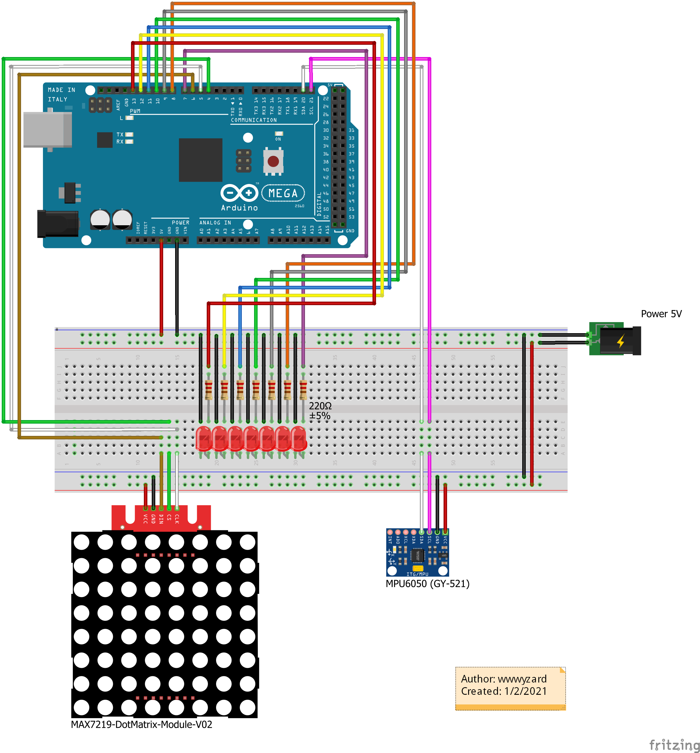
Wiring Diagram for this project
2Axis-Digital-Level-V1
Comments
Only logged in users can leave comments