Devices & Components
Arduino Nano
12v female adapter
A Box
Power cable 12V 10 A
DC Converter 12V to 5V
ZVS Module (with the coil)
Electrical wire
Mosfet switch
Arduino cable Male to Male - Male to female
10K omh resistor
Arduino prototyping square breadboard
18mm to 14mm WPA adapter
MOMENTARY SWITCH
Main ON-OFF Switch
Arduino nano shield
Circular piece of cork
Hardware & Tools
Double size tape
Screwdriver
Solder Iron
Project description
Code
PULSE Script
arduino
I made it the most simple that i could, if you’re lost, read the comment after every ‘’//‘’ they are there to guide you!
1const int mos = 8; // the pin that the mosfet switch is connected to the nano 2const int Switch = 2; // the pin that the momentary switch is connected to the nano 3int switchstate = 0; // variable for reading the button status 4 5void setup() { // don't touch that! 6 pinMode(mos, OUTPUT); // initalize the mosfet switch as an output 7 pinMode(Switch, INPUT); // initialize the momentary switch as an input 8} //never remove that symbol, are you crazy!!?? 9 10void loop(){ // don't touch that! 11 12 switchstate = digitalRead(Switch); // don't touch that! 13 14 if (switchstate == HIGH) // when you press the button 15 16 // this is where you can modify according to your preferences the pulse time and the waiting time between each pulse. 17 // (1 000 milliseconds = 1 second) (500 milliseconds = half a second) (High mean ON - Low mean Off) 18 19 { 20 21 digitalWrite(mos, HIGH); 22 delay(4000); // those 4 lines represent one pulse cycle. You can ad more or less pules cycle. *if you do this its verry important to put evry cycle inside those 2 symboles: { - } + dont change the order! 23 digitalWrite(mos, LOW); 24 delay(1000); 25 26 digitalWrite(mos, HIGH); 27 delay(4000); 28 digitalWrite(mos, LOW); 29 delay(1000); 30 31 digitalWrite(mos, HIGH); 32 delay(2000); 33 digitalWrite(mos, LOW); 34 delay(500); 35 36 digitalWrite(mos, HIGH); 37 delay(2000); 38 digitalWrite(mos, LOW); 39 delay(500); 40 41 digitalWrite(mos, HIGH); 42 delay(2000); 43 digitalWrite(mos, LOW); 44 delay(500); 45 46 digitalWrite(mos, HIGH); 47 delay(2000); 48 digitalWrite(mos, LOW); 49 delay(500); 50 51 digitalWrite(mos, HIGH); 52 delay(2000); 53 digitalWrite(mos, LOW); 54 delay(500); 55 56 digitalWrite(mos, HIGH); 57 delay(2000); 58 digitalWrite(mos, LOW); 59 delay(500); 60 61 digitalWrite(mos, HIGH); 62 delay(2000); 63 digitalWrite(mos, LOW); 64 delay(500); 65 66 digitalWrite(mos, HIGH); 67 delay(2000); 68 digitalWrite(mos, LOW); 69 delay(500); 70 71 digitalWrite(mos, HIGH); 72 delay(2000); 73 digitalWrite(mos, LOW); 74 delay(500); // Important AF! the last line (mos status) before this symbole: "}" will allways be: "digitalwrite(mos, low)". if its not that, the ZVS will stay ***ON*** 75 76 77 } 78 79 else // if the button is not pressed after a cycle or when you turn the device ON, The ZVS will be off 80 { 81 digitalWrite(mos,LOW); 82 // turn the mosfet OFF 83 } 84} 85
Downloadable files
Hardware connection circuit

Documentation
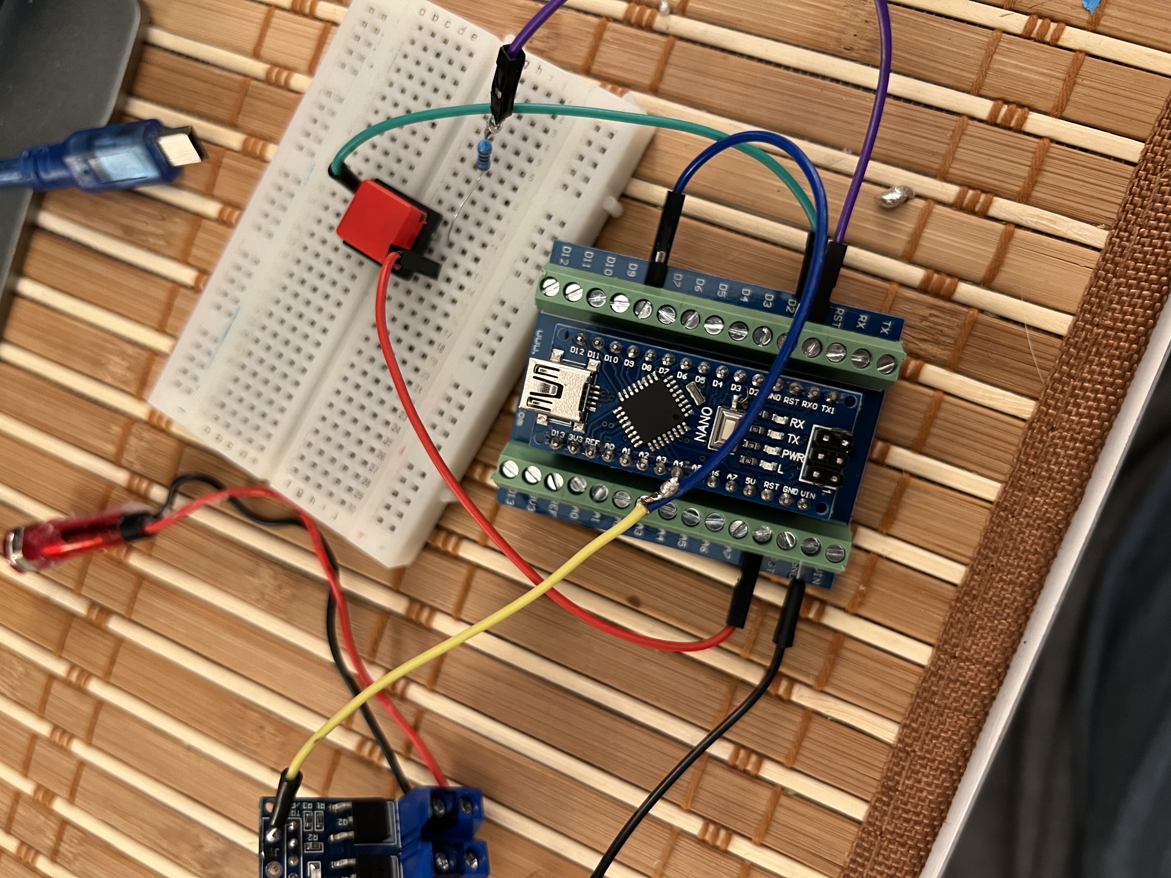
Here’s the connection between the MOSFET switch, momentary switch and Nano

Comments
Only logged in users can leave comments