Devices & Components
Arduino Uno Rev3
Real Time Clock (RTC)
IR transmitter (generic)
IR receiver (generic)
Hardware & Tools
Prototyping Kit, Breadboard
Software & Tools
Arduino IDE
Project description
Code
Tv audio damper with watchdog
arduino
The biggest problem is the instability of the microphone due to electrical/static noises or input voltage fluctuations. As example, if the audio goes above the hardware threshold, the output signal of the microphone will constantly remains above the setted threshold resulting in errors. The only way to avoid this (except using a better quality microphone amplifier?) is to restart the device. For this reason, a whatchdog is implemented. future improvements: - choosing threshold and time directly on the board - implement an automatic procedure to record the tv-controller signal leading the use to every kind of tv. - find a safe way to higher the volume to a fixed level - find a hardware design to optimize the audio uptake from tv
1#include <avr/wdt.h> 2#include <Wire.h> 3#include "RTClib.h" 4#include "IRremote.h" 5 6RTC_DS1307 rtc; //modulo ora 7float media_letture; 8int lettura; 9 10float media; 11int livello_suono; 12long somma = 0; 13int soglia_sup; 14int soglia_inf; 15int i; 16int lettura1; 17int lettura2; 18int lettura3; 19int lettura4; 20unsigned int ora; 21unsigned int rawData[67] = {4450, 4450, 550, 1700, 500, 1750, 500, 1700, 500, 600, 500, 600, 550, 550, 550, 600, 500, 600, 500, 1750, 500, 1700, 500, 1750, 500, 550, 550, 600, 500, 600, 500, 600, 550, 550, 550, 1700, 500, 1750, 500, 600, 500, 1700, 500, 600, 550, 550, 550, 600, 500, 600, 500, 600, 550, 550, 550, 1700, 500, 600, 500, 1750, 500, 1700, 500, 1750, 500, 1700, 500}; 22unsigned int timer; 23IRsend irsend; //Utilizzare PIN 3~ per LED IR 24int freq_ir = 38; 25 26void calibrazione() { 27 delay(20); 28 somma = 0; 29 lettura = 0; 30 soglia_sup = 0; 31 soglia_inf = 0; 32 media = 0; 33 for (i = 0; i < 50; i++) { 34 lettura = analogRead(A0); 35 somma = somma + lettura; 36 delay(30); 37 digitalWrite(8, HIGH); 38 } 39 40 media = (somma / 50); 41 soglia_sup = (int)(media) + 2 ; //valore soglia 42 soglia_inf = (int)(media) - 5 ; 43 digitalWrite(8, LOW); 44} 45 46 47void setup() { 48 49 wdt_disable(); 50 rtc.begin(); 51 52 pinMode(13, OUTPUT); 53 pinMode(18, OUTPUT); 54 //Serial.begin(9600); 55 calibrazione(); 56 wdt_enable(WDTO_500MS); 57} 58 59void loop() { 60 61 62 DateTime now = rtc.now(); //interroga il modulo ora 63 ora = now.hour(), DEC; 64 //Serial.println(ora); 65 //delay (300); 66 if (ora >=23 || ora <= 2) { 67 digitalWrite(13, LOW); 68 do { 69 if (analogRead(A0) > ((int)media + 18) || analogRead(A0) < ((int)media - 34)) { 70 delay(2000); 71 } 72 if (analogRead(A0) > soglia_sup) { 73 irsend.sendRaw(rawData, 67, freq_ir); 74 digitalWrite(13, HIGH); 75 //Serial.println(analogRead(A0)); 76 delay(200); 77 lettura1 = analogRead(A0); 78 delay(100); 79 lettura2 = analogRead(A0); 80 delay(100); 81 lettura3 = analogRead(A0); 82 somma = lettura1 + lettura2 + lettura3; 83 media = somma / 3; 84 if (int(media) > soglia_sup + 1) { 85 delay(2000); 86 } 87 88 } 89 else { 90 digitalWrite(13, LOW); 91 } 92 wdt_reset(); 93 lettura4 = analogRead(A0); 94 } while (lettura4 <= soglia_sup); 95 wdt_reset(); 96 } wdt_reset(); 97}
Downloadable files
TV audio damper
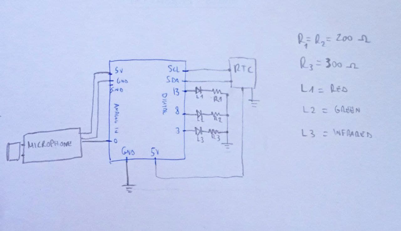
This is the final emitter circuit. Another schematics will be provided for the tv-control signal acquisition.
TV audio damper
TV audio damper
This is the final emitter circuit. Another schematics will be provided for the tv-control signal acquisition.
TV audio damper

Comments
Only logged in users can leave comments