Connecting BlueBus Technology photocells to Arduino
Let Arduino pilot photocells and other home automation sensors connected via the BlueBus Technology.
Components and supplies
1
Resistor 1k ohm
1
Resistor 4.7 ohm
1
Arduino Mega 2560
1
Arduino UNO
1
Resistor 10k ohm
1
Breadboard (generic)
1
General Purpose Transistor PNP
1
Test Accessory, AC Power Adaptor
1
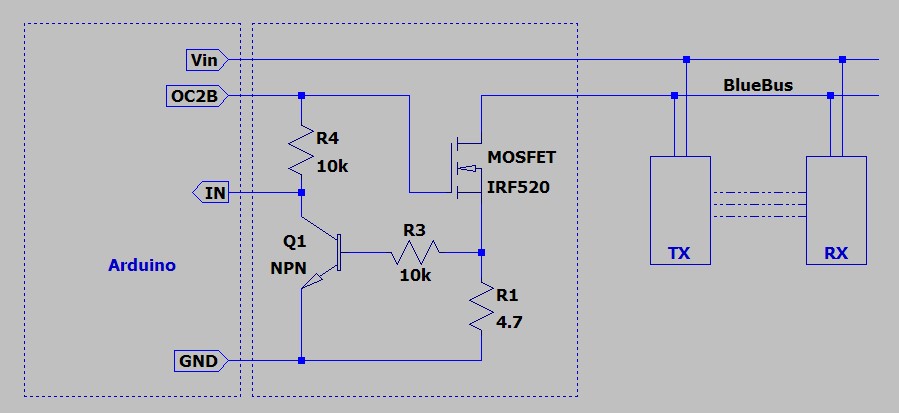
MOSFET Transistor, Switching
Apps and platforms
1
Arduino IDE
Project description
Code
bluebus.ino
c_cpp
INO file to open in the Arduino IDE
1/* Project: BlueBus
2 * Date   : 2022-10-31
3 * Author : Serge
4  */
5
6//============================================================================================
7//  BB module
8//============================================================================================
9
10//  OC2B, on MEGA2560 : PH6 = D9
11// OC2B, on UNO : PD3 = D3
12#if defined(__AVR_ATmega1280__)  || defined(__AVR_ATmega2560__)
13#define OC2B        9  /* Arduino Mega */
14#elif  defined(__AVR_ATmega644P__) || defined(__AVR_ATmega644__)
15#define OC2B        14  /* Sanguino */
16#else
17#define OC2B        3  /* Arduino Duemilanove, Diecimila,  LilyPad, etc */
18#endif
19
20// digitalWrite(OC2B, LOW);  => MOSFET blocked  => both bus lines pulled up to +Vin => 0V on the bus (active signal)
21#define  BB_ACTIVE LOW  // MOSFET blocked
22
23// digitalWrite(OC2B, HIGH); => MOSFET conducting  => 1 bus line connected to GND => Vin on the Bus (idle)
24#define BB_IDLE HIGH   // MOSFET conducting
25
26byte BB_in;                 // port number for reading  the bus
27volatile byte BB_reco = 0;  // trigger recognition phase
28byte BB_addr;               // current addr being scanned
29
30#define BB_EVENTS 32        //  max number of events waiting in the queue
31typedef struct {
32  byte evt;
33  unsigned long timestamp;
34  byte addr;
35  byte status;
36} BB_Event;
37volatile  BB_Event BB_events[BB_EVENTS];  // event queue
38BB_Event BB_event;                       //  one event
39volatile byte BB_event_in = 0;           // index of next event to  write to the queue
40volatile byte BB_event_out = 0;          // index of next  event to read from the queue
41
42// presence of devices on the bus, updated by  the recognition phase
43byte BB_device[16] = {
44  false, true,  false, false,  false, false, false, false, // device #1 is always scanned
45  false, false, false,  false, false, false, false, false,
46};
47
48// last status of each device (0xff  = no answer)
49byte BB_status[16] = {
50  0xff, 0xff, 0xff, 0xff, 0xff, 0xff,  0xff, 0xff,
51  0xff, 0xff, 0xff, 0xff, 0xff, 0xff, 0xff, 0xff,
52};
53
54void  BB_init(byte in);    // initialize and use port "in" to read the bus status
55void  BB_on();             // activate the bus, querying devices
56void BB_idle();           //  power the bus, but don't query any device
57void BB_off();            // power  off the bus
58void BB_recognition();    // initiate the recognition phase
59BB_Event*  BB_event_pop(); // get next event
60void BB_event_push(byte reply);   // add new  event to queue (called by ISR)
61
62// called by ISR in case of status change  on a device
63void BB_event_push(byte reply) {
64  byte status;
65
66  if (reply==0  || reply==0xff) {
67    status = 0xff;
68  } else {
69    status = ((reply ^  (reply>>4) ^ BB_addr) & 0b1111);
70    if (!BB_device[BB_addr]) {
71      BB_device[BB_addr]  = true;
72      BB_status[BB_addr] = 0xff;
73    }
74  }
75  if (status != BB_status[BB_addr])  {
76    volatile BB_Event* e;
77    BB_status[BB_addr] = status;
78    e = &BB_events[BB_event_in];
79    e->evt = true;
80    e->timestamp = micros();
81    e->addr = BB_addr;
82    e->status = status;
83    if (BB_event_in>=BB_EVENTS-1) {
84      BB_event_in  = 0;
85    } else {
86      BB_event_in++;
87    }
88    if (BB_event_in ==  BB_event_out) {
89      BB_event_pop();
90    }
91  }
92}
93
94// get next  event from the queue
95BB_Event* BB_event_pop() {
96  volatile BB_Event* out;
97  if (BB_event_in == BB_event_out) {
98    BB_event.evt = false;
99  } else {
100    out = &BB_events[BB_event_out];
101    BB_event.evt = out->evt;
102    BB_event.timestamp  = out->timestamp;
103    BB_event.addr = out->addr;
104    BB_event.status = out->status;
105    if (BB_event_out>=BB_EVENTS-1) {
106      BB_event_out = 0;
107    } else {
108      BB_event_out++;
109    }
110  }
111  return &BB_event;
112}
113
114void BB_init(byte  in) {
115
116  BB_in = in; // port used for reading the bus
117  pinMode(OC2B, OUTPUT);
118  pinMode(BB_in, INPUT);
119
120  // no power on the bus
121  BB_off();
122
123  // CPU clock is 16MHz (MEGA2560)
124  // CS2 = 0b101 = clock divided by 128
125  // TCNT incremented every 8µs (128/16M = 8µ)
126  TCCR2B &= 0xff ^ (_BV(CS22)  | _BV(CS21) | _BV(CS20)) ;
127  TCCR2B |= _BV(CS22) | _BV(CS20) ;
128
129  // EXCLK  = 0, internal clock
130  ASSR &= 0xff ^ _BV(EXCLK);
131
132  // AS2 = 0, asynchrone  mode
133  ASSR &= 0xff ^ _BV(AS2);
134
135  // COM2A = COM2B = 00 : normal port  operation
136  TCCR2A &= 0xff ^ (_BV(COM2A1) | _BV(COM2A0) | _BV(COM2B1) | _BV(COM2B0));
137
138  // COM2B = 11 : inverted output (LOW at start, HIGH when OCR2B is reached
139#define  BB_ACTIVATE_SIGNAL() TCCR2A |= _BV(COM2B1) | _BV(COM2B0);
140
141  // COM2B = 00  : normal port operation
142#define BB_DEACTIVATE_SIGNAL() TCCR2A &= 0xff ^ (_BV(COM2B1)  | _BV(COM2B0));
143  BB_DEACTIVATE_SIGNAL();
144
145  // WGM2 = 0b111 => fast PWM  mode, TOP=OCRA
146  TCCR2A |= (_BV(WGM21) | _BV(WGM20));
147  TCCR2B |= _BV(WGM22);
148
149//  |------------32ms-------------|  |------------19-------|
150// |xxxxxxxx0-------16.9ms-------|  |xxxxxxxx0-------10---|
151// |xxxxxxxx0yyyyyyyy0---1.8ms---|  |xxxxxxxx0yyyyyyyy0-1-|
152//
153//  19-bit frame (8 bits + stop + 8 bits + stop + 1 idle bit) lasting 32ms => 1.68ms/bit  => 210 ticks of 8µs
154// very little delay measured before the start of the first  bit of yyyyyyyy, about 0.3ms (210/6=35 ticks)
155
156#define BB_FRAME 210
157  OCR2A  = BB_FRAME;
158
159//                 _0.56_                 __70__
160// 1  |___1.1ms___|      |     |___140___|      |
161//
162//            ___1.1ms___              ___140___
163//  0  |_0.56_|           |     |__70__|         |
164//             ^                        ^
165//  read      __|                      __|
166//
167// Bit 0 transmitted as 1/3 LOW  + 2/3 HIGH
168#define BB_BIT0 (BB_FRAME/3)
169// Bit 1 transmitted as 2/3 LOW +  1/3 HIGH
170#define BB_BIT1 ((BB_FRAME/3)*2)
171// middle of a bit for reading its  state (+estimated delay for reply to start)
172#define BB_BITR (BB_FRAME/2 + BB_FRAME/6)
173  OCR2B = BB_BITR;
174
175}
176
177#define PARITY(x) (((x) + ((x)>>1) + ((x)>>2)  + ((x)>>3) + ((x)>>4) + ((x)>>5) + ((x)>>6) + ((x)>>7)) & 0b1)
178
179// called  by ISR to get next BB_addr to query, in recognition phase and in norml operation  phase
180byte BB_sequence() {
181  static byte addr = 0;
182  static byte reco_count  = 0;
183  byte byteQ;
184  byte flag;
185
186  // normal operation, query each recognized  device
187  if (BB_reco==0) {
188    flag = 1;
189    do {
190      addr = (addr+1)  & 0b1111;
191    }
192    while (!BB_device[addr]);
193  }
194
195  // start recognition  phase, starting with addr #1
196  if (BB_reco==1) {
197    addr = 1;
198    reco_count  = 2;
199    BB_reco++;
200  }
201
202  // recognition phase running, test twice  each address from 1 to 15
203  if (BB_reco>1) {
204    flag = 0;
205    if (reco_count)  {
206      reco_count--;
207    } else {
208      addr++;
209      reco_count =  2;
210      if (addr>15) {
211        BB_reco = 0;
212        addr = 0;
213      }
214    }
215  }
216
217  // data to send : aabcccfp
218  //    aa : address extension  (0 ?)
219  //    b  : address modifier (A bridge on the board)
220  //    ccc :  addr as configured with the jumpers
221  //    f : reset flag ? should be 1 for  normal operation
222  //    p : parity bit
223  BB_addr = addr;
224  byteQ = (addr<<2)  | (flag<<1);
225  // set parity bit
226  byteQ ^= PARITY(byteQ);
227  return byteQ;
228}
229
230//  Interrupt service routine triggered when TIMER2 reach OCR2B value
231ISR(TIMER2_COMPB_vect)  {
232  static byte bit_count = 0;
233  static byte data = 0;
234
235  // ==========  send the query ==========
236  // activate timer signal
237  if (bit_count==0) {
238    data = BB_sequence();
239    BB_ACTIVATE_SIGNAL();
240  }
241
242  // Q 8bits  + stop bit (zero)
243  if (bit_count<9) {
244    OCR2B = (data & _BV(7)) ? BB_BIT1  : BB_BIT0;
245    data <<= 1;
246  }
247
248  // end of byteQ, deactivate
249  if  (bit_count==9) {
250    BB_DEACTIVATE_SIGNAL();
251    OCR2B = BB_BITR;
252    data  = 0;
253  }
254
255  // ========== read the status ==========
256  // start to read  8 bits on **next** cycle
257  if (bit_count>=10 && bit_count<18) {
258    data =  (data<<1) + (digitalRead(BB_in) ? 0 : 1);
259  }
260
261  // stop bit (should be  zero)
262  if (bit_count==18) {
263    BB_event_push(data);
264  }
265
266  // one  frame (32ms) = 9+9+1 bits
267  if (bit_count<18) {
268    bit_count++;
269  } else  {
270    bit_count = 0;
271  }
272}
273
274void BB_on() {
275
276  // Interrupt  on Comparator B only: OCIE2B=1, OCIE2A=0, TOIE2=0
277  TIMSK2 &= 0xff ^ (_BV(OCIE2A)  | _BV(OCIE2B) | _BV(TOIE2));
278  TIMSK2 |= _BV(OCIE2B);
279  // bus powered
280  digitalWrite(OC2B, BB_IDLE);
281}
282
283void BB_idle() {
284
285  // No interrupt:  OCIE2B=0, OCIE2A=0, TOIE2=0
286  TIMSK2 &= 0xff ^ (_BV(OCIE2A) | _BV(OCIE2B) | _BV(TOIE2));
287  // no query but bus still powered
288  digitalWrite(OC2B, BB_IDLE);
289
290}
291
292void  BB_off() {
293
294  // No interrupt: OCIE2B=0, OCIE2A=0, TOIE2=0
295  TIMSK2 &=  0xff ^ (_BV(OCIE2A) | _BV(OCIE2B) | _BV(TOIE2));
296  // no power on the bus
297  digitalWrite(OC2B, BB_ACTIVE);
298
299}
300
301// initiate recognition phase.  It will last about 15*2*32ms = 1 second
302void BB_recognition() {
303  BB_reco  = 1;
304}
305
306//============================================================================================
307
308void  setup() {                      // setup(): put your setup code here, to run once:
309
310  Serial.begin(2e6);
311  Serial.println("\
312\
313\
314\
315INIT...");
316
317  pinMode(LED_BUILTIN,  OUTPUT);
318  digitalWrite(LED_BUILTIN, HIGH);
319
320  BB_init(3);       // read  bus on port D3
321  BB_on();          // activate bus and communication
322  delay(1000);      // wait for the devices to power-up
323  BB_recognition(); // initiate a recognition  phase
324
325  digitalWrite(LED_BUILTIN, LOW);
326  Serial.println("INIT... Completed!");
327}
328
329void  loop() {                       // loop(): put your main code here, to run repeatedly:
330
331  BB_Event* e;
332
333  while ((e=BB_event_pop())->evt) {
334    Serial.print("Device  ");
335    Serial.print(e->addr, HEX);
336    Serial.print(", status ");
337    Serial.print(e->status, HEX);
338    Serial.print(", timestamp ");
339    Serial.println(e->timestamp);
340    digitalWrite(LED_BUILTIN, e->status & 0b0010 ? HIGH : LOW);
341  }
342  delay(200);
343}
344
345
Downloadable files
Schematics of the small hardware piece
Schematics of the small hardware piece
Comments
Only logged in users can leave comments