FlowSense Alert
Real-time Water Flow Monitoring System with Flow Rate Display and Threshold Alert
Devices & Components
1
Arduino Uno Rev3
1
Water Flow Sensor
1
12 volt Adapter
1
7 segment 4 digit display
1
9V Battery Clip
1
jumper wires for arduino
Hardware & Tools
1
Soldering Gun Kit, Instant Heat
1
Solder Soldering Wire
Software & Tools
Arduino IDE
Project description
Code
Water Flow Sensor
cpp
Downloadable files
7 segment 4 digit Display
Download and include the file to the library
TM1637-master.zip
Documentation
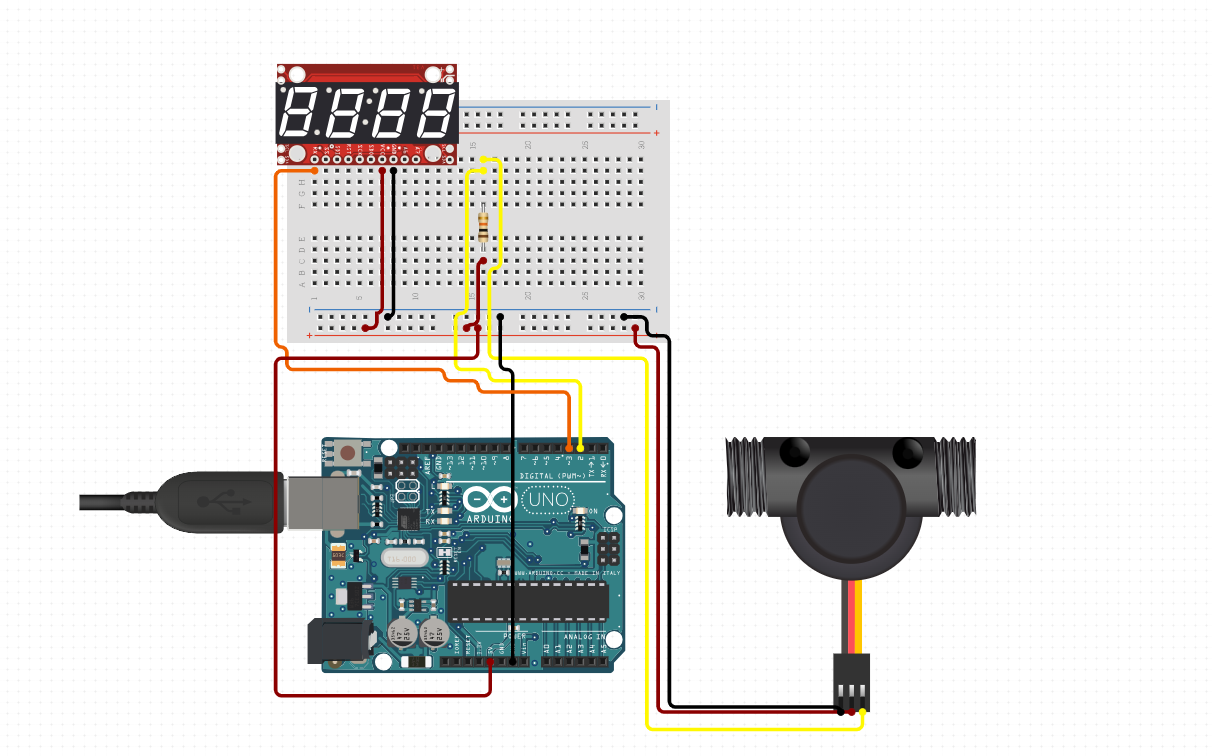
Circuit Diagram
Connect the circuit according to the diagram
3ae756bf-c335-4dd2-98ff-08ba5011e243.png
Connection
file.None
Comments
Only logged in users can leave comments