DIY Golf Cart with Bluetooth, Cruise Control, Odometer and Shot Distance Measurement
A reliable, robust, easy to assemble and use Golf Buggy with some unique features.
Devices & Components
2
Arduino Nano
Software & Tools
1
Arduino Bluetooth Control
Project description
Code
BlueTooth Golf Buggy Receiver
cpp
1//Pin 2 is hardware interrupt for hall effect sensor. MUST have input_pullup.
2//Pin 3 is Left motor forward pin
3//Pin 4 is for LED display DI01 (TM1637)
4//Pin 5 is Arduino Rx pin connected to HC-05 Tx pin
5//Pin 6 is Arduino Tx pin connected to HC-05 Rx pin. MUST have voltage divider. 4.7k / 10k resistor series pair from Pin 6 to ground.
6//Pin 7 is for LED display CLK1
7//Pin 9 is Right motor forward pin
8//Pin 10 is Both motor reverse pin. Connect both L pins on H-Bridges to this
9
10#include <TM1637Display.h>  //Library for LED display
11#include <SoftwareSerial.h> //Library to allow change of Tx and Rx pins
12#include <PWM.h>            //Library to allow changes to default PWM from 500Hz to 15kHz. Motors are noisy at 500Hz
13#include "RTClib.h"         // Library fro real time clock module
14#include <Wire.h>
15
16#define   rxPin 5           //Defines software serial Arduino Rx pin
17#define   txPin 6           //Defines software serial Arduino Tx pin
18#define   CLK1 7            //LED clock pin
19#define   DIO1 4            //LED data pin
20#define   TIME_24_HOUR (true);
21
22RTC_DS3231 rtc;
23
24TM1637Display display1 = TM1637Display(CLK1, DIO1); // Create a display object of type TM1637Display for LED readout
25
26unsigned long eventTime = 0;  // Used for timeout safety control
27unsigned long Time = 0;       // Same as above
28unsigned long Count = 0;      // Used for Shot measurement calcs
29int SpeedL = 0;               // Left motor speed
30int SpeedR = 0;               // Right motor speed
31int Shot = 0;                 // Used for Shot measurement calcs
32int shotOn = 0;               // Used for Shot measurement calcs
33float Distance = 0;           // Used for odometer calcs
34float interruptTime = 0;      // Time of interrupt on Pin 2
35float lastInterruptTime = 0;  // Time of last interrupt on Pin 2
36bool measureOn = false;       // Boolean to initiate Shot measurement calcs
37bool clockOn = false;         // Turns clock display on/off
38bool cruiseOn = false;        // Boolean variable for cruise control on/off
39float timeDelay = 0;          // Main input for cruise control
40float Error = 0;              // Cruise control input
41float Setpoint = 0;           // Cruise control setpoint
42int Output = 0;               // Cruise control output
43float oldError = 0;           // Cruise control previous error
44float Kp = 0.1;               // Sets proportional gain
45float Ki = 1.0;               // Sets integral gain
46float Kd = 0.1;               // Sets derivative gain
47float pTerm = 0;              // Proprotional correction
48float iTerm = 0;              // Integral correction
49float dTerm = 0;              // Derivative correction
50float Correction = 0;         // Total PID correction
51
52SoftwareSerial mySerial =  SoftwareSerial(rxPin, txPin); // Set up a new SoftwareSerial object for HC-05
53
54void setup()  {
55
56  pinMode(rxPin, INPUT);    // Define pin modes for HC05 Rx
57  pinMode(txPin, OUTPUT);   // Define pin modes for HC05 Tx
58  pinMode(3, OUTPUT);       // Left Motor Forward
59  pinMode(9, OUTPUT);       // Right Motor Forward
60  pinMode(10, OUTPUT);      // Both Motors Reverse
61  pinMode(2, INPUT_PULLUP); // Interrupt attached to Hall Effect sensor
62
63  //Check if RTC is connected correctly:
64  if (!rtc.begin()) {
65    while (1);
66  }
67
68  //rtc.adjust(DateTime(2025, 7, 10, 10, 57, 0)); // Adjust clock time if power is lost
69
70  attachInterrupt(digitalPinToInterrupt(2), changed, RISING); // Triggers timing on falling value from Hall Effect sensor
71
72  mySerial.begin(9600); // Set the baud rate for the SoftwareSerial object for HC05 communications
73
74  InitTimersSafe();              // Initialize Arduino timers 1 and 2 to change PWM frequency from 500Hz to 15kHz.
75  SetPinFrequencySafe(3, 15000); // Change PWM refquency to 15000Hz on Pin 3
76  SetPinFrequencySafe(9, 15000); // Change PWM refquency to 15000Hz on Pin 9
77
78  display1.setBrightness(6); // Sets parameters for LED display
79
80  //Serial.begin (115200);
81
82}
83
84void loop()
85{
86
87  //This section for cruise control
88
89  timeDelay =  interruptTime - lastInterruptTime;
90  lastInterruptTime = interruptTime;
91
92  if (timeDelay != 0) {
93
94    //Note,the math relationship between Setpoint and SpeedR on my rig
95    //is the power series (17734 * (SpeedR ^ -1.09)).
96    //Setpoint is therefore a function of the SpeedR selected
97    //You can determine this equation by running various values of SpeedR and measuring the timeDelay for each pulse.
98    //Plot SpeedR against the measured timeDelay on an Excel spreadsheet using X against Y graphics and fit a power curve to the data.
99    //Read off the fitted equation from the graph.
100
101    Setpoint = pow(SpeedR, -1.09);
102    Setpoint = (Setpoint * 17734);
103
104    Error = Setpoint - timeDelay; // Uphill Error is +ve.
105
106    pTerm = (Kp * Error);            // Proportional correction
107    iTerm = (Ki * (Error + oldError)); // Integral correction
108    dTerm = (Kd * (Error - oldError)); // Derivative correction
109
110    Correction = (pTerm + iTerm + dTerm); // Total correction
111
112    if (cruiseOn == false) Output = SpeedR; // Output with no PID
113
114    if (cruiseOn == true) Output = (SpeedR - Correction); // Output with PID. Cruise is engaged for an speed above 100 by button 4
115  }
116
117  if (Output > 250) Output = 250;    // Limit the output to PWM limits
118  if (Output <= 0) Output = 0;
119
120  if (cruiseOn == true && timeDelay != 0) {  // If Cruise Control enabled and the buggy is moving speed will be adjusted using PID output
121
122    pwmWrite (3, Output);
123    pwmWrite (9, Output);
124  }
125
126  if (Error != 0) oldError = Error;
127
128  // This section is Distance calcs
129
130  Distance = (Count * 0.13089); // Calculates distance in metres travelled using pulses recieved. 6 pulses per rev at 0.785398 metres wheel circumference
131  shotOn = (Shot * 0.13089);    // Variable for converting magnetic pulses to shot distance
132
133  // This section for what to display on the LED
134
135  if (cruiseOn == false) {
136    display1.showNumberDec(SpeedR, false, 3, 1);
137  }
138
139  if (cruiseOn == true) {
140    display1.showNumberDec(Output, false, 3, 1);
141  }
142
143  if (clockOn == true && SpeedR == 0) {
144
145    display1.clear();
146    display1.showNumberDec(shotOn, false, 3, 1);
147    delay(2000);
148    display1.clear();
149
150    display1.showNumberDec(Distance, false, 4, 0);
151    delay (2000);
152    display1.clear();
153
154    DateTime now = rtc.now();// Get current date and time:
155    int displaytime = (now.hour() * 100) + now.minute();  // Create time format to display:
156    display1.showNumberDecEx(displaytime, 0b11100000, false);  // Display the current time in 24 hour format with leading zeros enabled and a center colon:
157    delay (2000);
158    clockOn = false;
159    display1.clear();
160  }
161
162  //This section initiates automatic timeout and stop if connection is lost. Continuous "G" is sent by Tx and if lost for 5 seconds then auto stop.
163
164  Time = millis() - eventTime; //measures time from last G character received.
165
166  if (Time > 5000)
167  {
168    // Stop everything if bluetooth is lost
169    SpeedL = 0;
170    SpeedR = 0;
171    pwmWrite (3, SpeedL);
172    pwmWrite (9, SpeedR);
173    pwmWrite (10, 0);
174  }
175/*
176  if (timeDelay != 0) {
177    Serial.print (    "  timeDelay "    );
178    Serial.print (timeDelay);
179    Serial.print (    "  SpeedR "    );
180    Serial.print (SpeedR);
181    Serial.print (    "   Setpoint    "    );
182    Serial.print (Setpoint);
183    Serial.print (    "   Correction    "    );
184    Serial.print (Correction);
185    Serial.print (    "     Output   "    );
186    Serial.println (Output);
187  }
188*/
189
190
191  char data; // Data is the variable for the code coming from HC-05
192
193  if (mySerial.available() > 0)  // If HC-05 is connected
194
195  {
196    char data = mySerial.read(); // Read the data received from the bluetooth module
197
198    switch (data) // Starts the switch function if data is available
199    {
200
201      case 'G':                   //Reset timeout. Received every second to ensure communications
202        eventTime = millis();
203        break;
204
205      case '1':                   //Turn Left
206        pwmWrite(10, 0);          //stop reverse pin output
207        pwmWrite(3, 0);           //Stop left motor
208        pwmWrite(9, 250);         //Full power right motor
209        delay(300);               //left turn for 300 milliseconds
210        pwmWrite (3, SpeedL);     //Restore to original speed
211        pwmWrite (9, SpeedR);     //Restore to original speed
212        break;
213
214      case '2':                         //Go faster
215        cruiseOn = false;               //Disable cruise control
216        pwmWrite(10, 0);                //Stop reverse pin output
217        SpeedL = (SpeedL + 10);         //Increase speed by 10% each press
218        SpeedR = (SpeedR + 10);         //Increase speed by 10% each press
219        if (SpeedL < 100) SpeedL = 100; // Skip the first few speed steps
220        if (SpeedR < 100) SpeedR = 100; // Skip the first few speed steps
221        pwmWrite(3, SpeedL);            //Send speed setting to left motor
222        pwmWrite(9, SpeedR);            //Send speed setting to right motor
223        break;
224
225      case '3':                   //Turn Right
226        pwmWrite(10, 0);          //Stop reverse pin output
227        pwmWrite(9, 0);           //Stop right motor
228        pwmWrite(3, 250);         //Full power left motor
229        delay (300);              //Right turn for 300 milliseconds
230        pwmWrite (9, SpeedR);     //return to original speed
231        pwmWrite (3, SpeedL);     //return to original speed
232        break;
233
234      case '4':
235        if (cruiseOn) {
236          cruiseOn = false;          // Toggle to false. If its on, turn it off
237        }
238        else {
239          cruiseOn = true;           // Toggle to true. If its off, turn it on
240        }
241        break;
242
243      case '5':
244        SpeedR = 120;
245        SpeedL = 120;
246        pwmWrite(10, 0);            //stop reverse pin output
247        pwmWrite (9, 100);          //Send speed setting to right motor
248        pwmWrite (3, 100);          //Send speed setting to left motor
249        pwmWrite (9, 120);          //Send speed setting to right motor
250        pwmWrite (3, 120);          //Send speed setting to left motor
251        cruiseOn = true;            //Enable cruise control
252        break;
253
254      case '6':
255        SpeedR = 130;
256        SpeedL = 130;
257        pwmWrite(10, 0);            //stop reverse pin output
258        pwmWrite (9, 100);          //Send speed setting to right motor
259        pwmWrite (3, 100);          //Send speed setting to left motor
260        pwmWrite (9, 130);          //Send speed setting to right motor
261        pwmWrite (3, 130);          //Send speed setting to left motor
262        cruiseOn = true;            //Enable cruise control
263        break;
264
265      case '7':
266        SpeedR = 140;
267        SpeedL = 140;
268        pwmWrite(10, 0);            //stop reverse pin output
269        pwmWrite (9, 100);          //Send speed setting to right motor
270        pwmWrite (3, 100);          //Send speed setting to left motor
271        pwmWrite (9, 140);          //Send speed setting to right motor
272        pwmWrite (3, 140);          //Send speed setting to left motor
273        cruiseOn = true;            //Enable cruise control
274        break;
275
276      case '8':
277        cruiseOn = false;           //Disable cruise control
278        pwmWrite(10, 0);            //stop reverse pin output
279        SpeedL = (SpeedL - 10);     //Go slower, decrease speed by 10% each press
280        SpeedR = (SpeedR - 10);     //Go slower, decrease speed by 10% each press
281        pwmWrite(3, SpeedL);        //Send speed setting to left motor
282        pwmWrite(9, SpeedR);        //Send speed setting to right motor
283        break;
284
285      case '9':                    //reset distance counter for shot measurement
286        if (measureOn) {
287          measureOn = false;      // Toggle to false. If its on, turn it off
288        }
289        else {
290          measureOn = true;       // Toggle to true. If its off, turn it on
291        }
292        Shot = 0;
293        break;
294
295
296      case '0':                     // Display shot and distance measurements then current time
297        if (clockOn) {
298          clockOn = false;          // Toggle to false. If its on, turn it off
299        }
300        else {
301          clockOn = true;           // Toggle to true. If its off, turn it on
302        }
303        break;
304
305      case '#':                   //Reverse
306        cruiseOn = false;         //Disable cruise control
307        pwmWrite (3, 0);          //Stop forward pin output
308        pwmWrite (9, 0);          //Stop forward pin output
309        SpeedL = 0;               //Both motors stop
310        SpeedR = 0;               //Both motors stop
311        delay (200);              //Give the buggy time to stop
312        pwmWrite(10, 120);        //Drive both motors reverse
313        break;
314
315      case '*':                   //Stop
316        cruiseOn = false;         //Disable cruise control
317        pwmWrite(10, 0);          //Stop reverse pin output
318        SpeedL = 0;               //Both motors stop
319        SpeedR = 0;               //Both motors stop
320        Output = 0;
321        pwmWrite (9, SpeedR);
322        pwmWrite (3, SpeedL);
323        break;
324
325      default : break;
326    }
327  }
328}
329
330// Calls the time an interrupt occured on pin 2
331void changed() {
332  Count = ++ Count; // Counts pulses for odometer. Increment count by one each pulse
333  Shot = ++ Shot;   // Counts pulses for shot measurement. Increment count by one each pulse
334  interruptTime = (millis()); //Time of interrupt
335}
BlueTooth Golf Buggy Tx Code
cpp
1//Bluetooth Golf Buggy Transmitter Code
2
3
4#include <SoftwareSerial.h>
5#include <Keypad.h>
6
7SoftwareSerial B(11,10); // Sets HC-05 connection pins. 11 = HC-05 Tx, 10 = HC-05 Rx
8
9//Slave HC-05 code (5856,00,00EEFB)
10
11unsigned long startTime = 0; //Variable time for 1 second time interval for transmission of connection check character G
12const long interval = 1000; //Constant for 1 second time interval for transmission of connection check character G
13const int txPin = 10;
14
15const byte ROWS = 4; //four rows
16const byte COLS = 3; //four columns
17char keys[ROWS][COLS] = {
18  {'1','2','3'},
19  {'4','5','6'},
20  {'7','8','9'},
21  {'*','0','#'}
22};
23
24byte rowPins[ROWS] = {9, 8, 7, 6}; //connect to the row pinouts of the keypad
25byte colPins[COLS] = {5, 4, 3}; //connect to the column pinouts of the keypad
26
27
28  //1=5,2=4,3=3,4=2,5=9,6=8,7=7,8=6,10=HC Rx,11=HC Tx.
29
30
31Keypad keypad = Keypad( makeKeymap(keys), rowPins, colPins, ROWS, COLS );
32
33void setup()
34{
35
36  pinMode (10, OUTPUT); //HC-05 Rx
37  pinMode (11, INPUT); //HC-05 Tx
38  Serial.begin(9600);
39  B.begin(9600); //Required for HC-05 serial port
40}
41
42void loop(){
43  char key = keypad.getKey();
44
45  if (key){
46    Serial.println(key);
47    B.println (key);
48    //delay(100);
49  }
50
51  // Next lines for transmission every second to test comms connection. Rx stops all movement after 5 seconds if not receiving G
52
53  unsigned long onTime = millis();//Sets variable onTime to current time
54
55  if (onTime >= startTime + interval) //Tests if onTime is greater than variable time (startTime) plus transmission interval (1000ms)
56  {
57  txPin == HIGH;
58  Serial.println ("G");
59  B.println ("G");//Sends G
60  startTime = millis();//Resets variable time to current time
61  txPin == LOW;
62  }
63
64}
Downloadable files
Buggy Rx Schematic
New schematic with RTC connections shown.
Schematic_Buggy-Rx-1_2026-03-18.pdf
Documentation
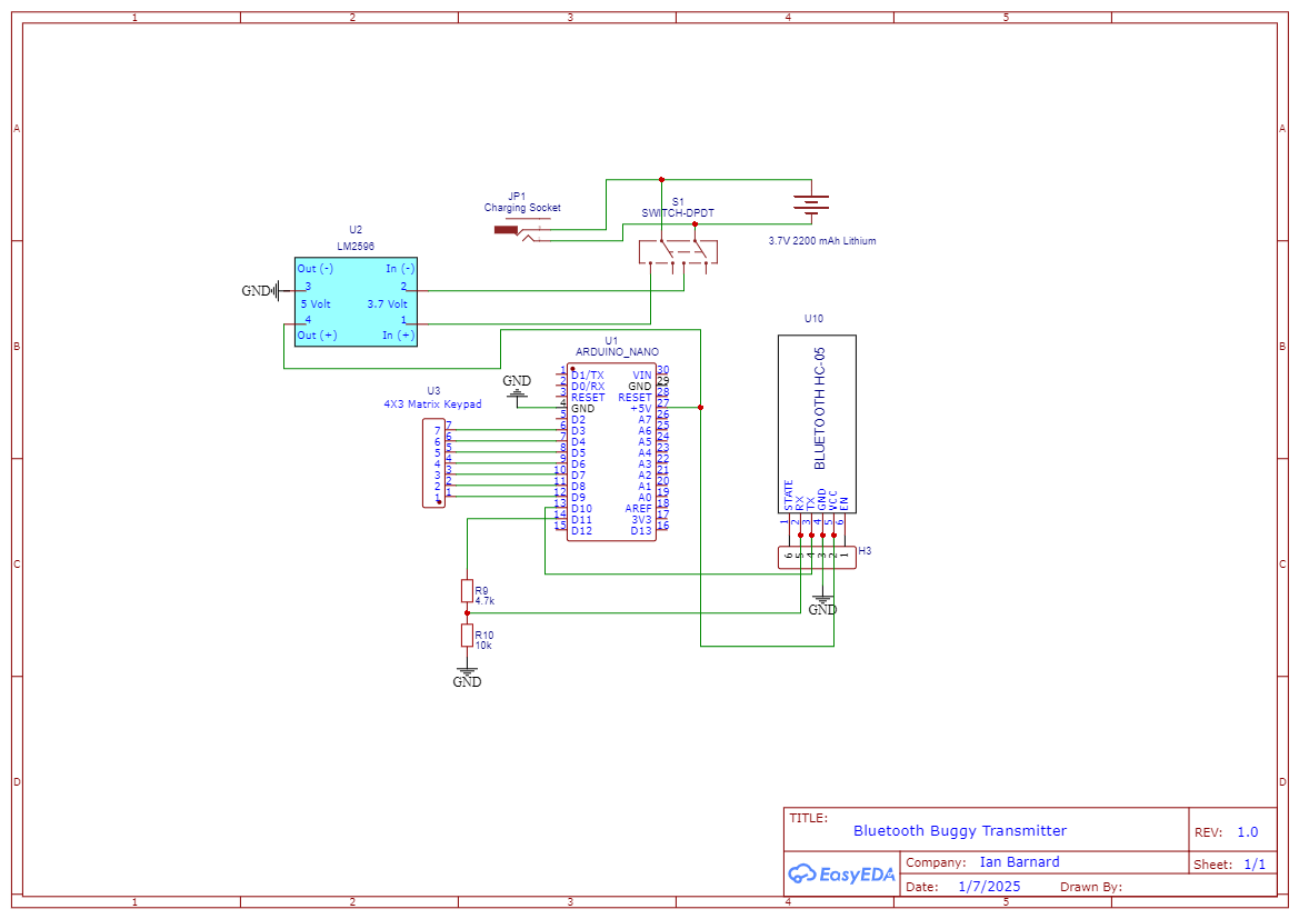
Bluetooh Buggy Transmitter
Schematic_Buggy-TX-PCB-1_2025-07-01.png
Comments
Only logged in users can leave comments