Software & Tools
Arduino IDE
Project description
Code
Sensors Code
arduino
Motor Code
arduino
Sensors Code
arduino
Downloadable files
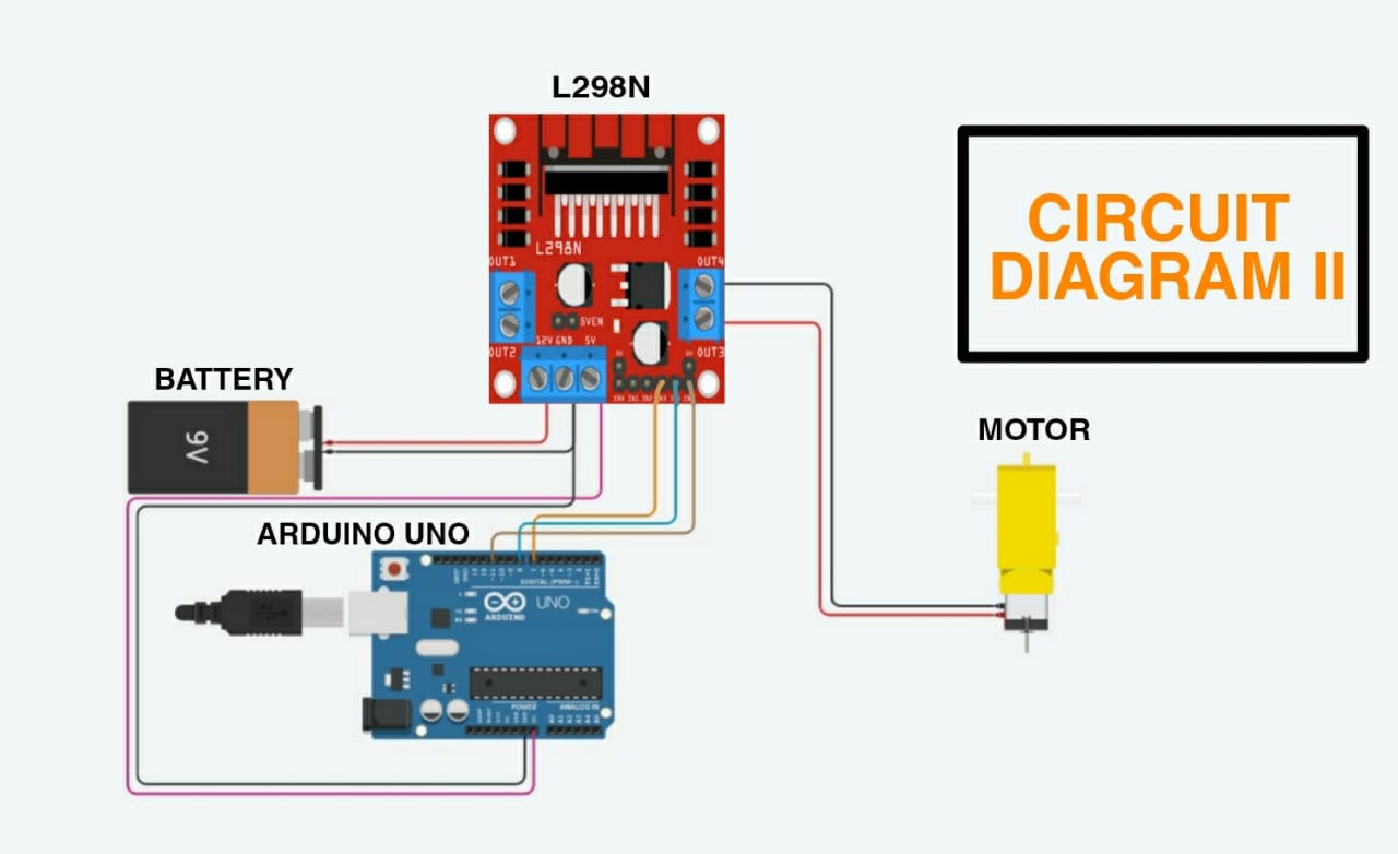
Simulated Circuit Diagram
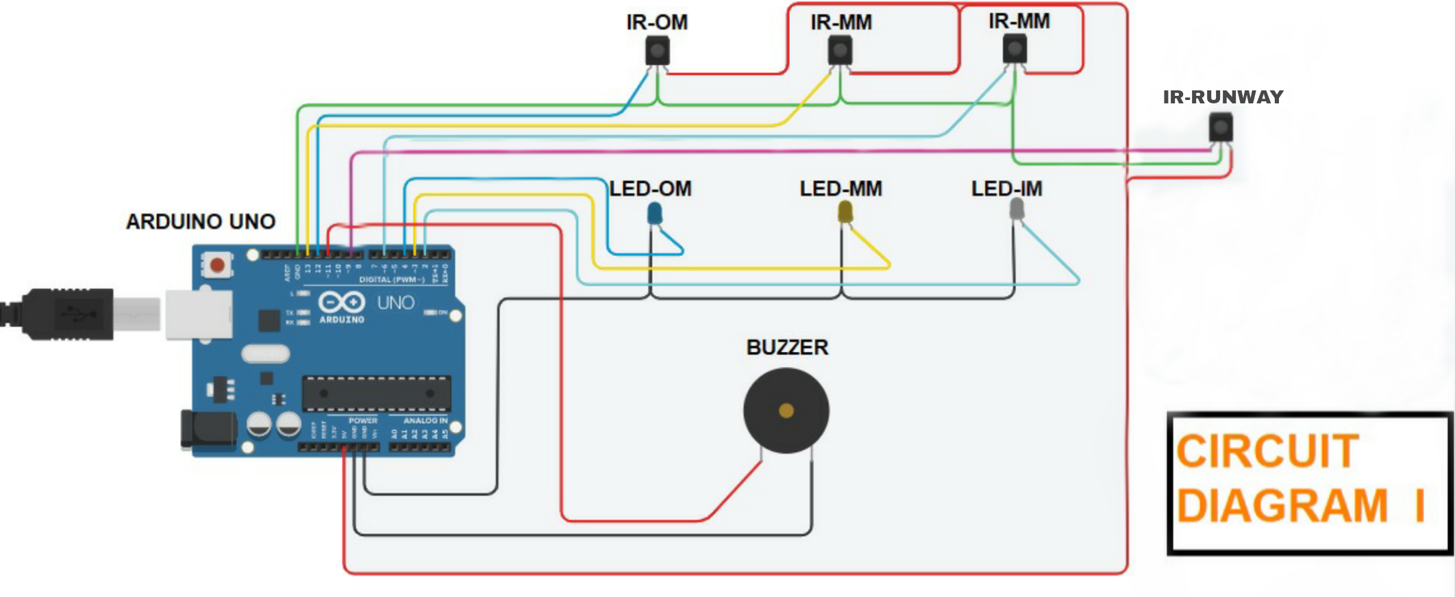
A) IR Proximity sensor connections: 1. Connect OUT of inner marker (Sensor) to Arduino's digital pin 6. 2. Then connect the OUT of middle marker (Sensor) to Arduino's digital pin 7. 3. Same as inner and middle connect the OUT of outer marker (Sensor) to Arduino's digital pin 8 4. Then connect OUT of NRI (No Return Indication sensor) to Arduino's digital pin 10. 5. Connect the GRD i.e. (ground) of all sensors to Arduino's pin ground. 6. Connect VCC of all sensors to Arduino's pin of +5 V. B) LED's connections: 1. Connect +ve terminal of inner marker (LED) to arduino's digital pin 4. 2. Then connect the +ve terminal of middle marker (LED) to Arduino's digital pin 2. 3. Connect the +ve of outer marker (LED) to Arduino's digital pin 3. 4. After that connect all the -ve outer marker (LED) to Arduino's pin ground. C) Buzzer connection: 1. Connect one terminal to Arduino's digital pin 11. 1. Connect another terminal to arduino's Pin GRD.
Simulated Circuit Diagram
Simulated Circuit Diagram
A) IR Proximity sensor connections: 1. Connect OUT of inner marker (Sensor) to Arduino's digital pin 6. 2. Then connect the OUT of middle marker (Sensor) to Arduino's digital pin 7. 3. Same as inner and middle connect the OUT of outer marker (Sensor) to Arduino's digital pin 8 4. Then connect OUT of NRI (No Return Indication sensor) to Arduino's digital pin 10. 5. Connect the GRD i.e. (ground) of all sensors to Arduino's pin ground. 6. Connect VCC of all sensors to Arduino's pin of +5 V. B) LED's connections: 1. Connect +ve terminal of inner marker (LED) to arduino's digital pin 4. 2. Then connect the +ve terminal of middle marker (LED) to Arduino's digital pin 2. 3. Connect the +ve of outer marker (LED) to Arduino's digital pin 3. 4. After that connect all the -ve outer marker (LED) to Arduino's pin ground. C) Buzzer connection: 1. Connect one terminal to Arduino's digital pin 11. 1. Connect another terminal to arduino's Pin GRD.
Simulated Circuit Diagram
Documentation
CUSTOM PARTS AND ENCLOSURES
CUSTOM PARTS AND ENCLOSURES
CUSTOM PARTS AND ENCLOSURES
CUSTOM PARTS AND ENCLOSURES
Comments
Only logged in users can leave comments