Six sided die sketch, part 1
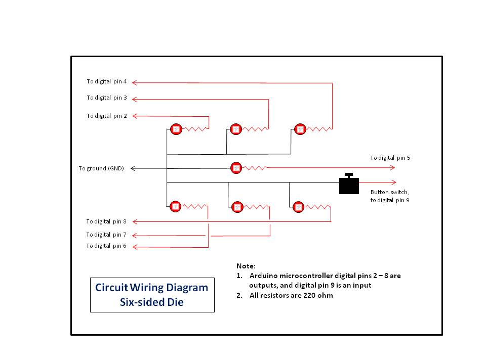
A sketch to 'throw' a six sided die using a partial 3 x 3 matrix of LEDs, driven directly from the microcontroller
Devices & Components
1
Arduino Uno Rev3
7
Resistor 220 ohm
7
5 mm LED: Red
1
Development Kit Accessory, Jumper Wire Kit
1
Tactile Switch, Top Actuated
1
Solderless Breadboard Half Size
8
Jumper wires (generic)
Software & Tools
Arduino IDE
Project description
Code
Six side die sketch part 1
c_cpp
A sketch that randomly throws a standard six side die.
1//
2// Ron Bentley, Stafford, UK, December 2021
3// This code is in  the public domain and is offered without warranty
4//
5// Rolling the Dice,  part 1 of 2 parts
6// ^^^^^^^^^^^^^^^^^^^^^^^^^^^^^^^^^^^
7// A sketch to use  with board games (or any game), where a die/dice is/are required, to
8// throw  a six sided die. However, the sketch may be easily modified to
9// work with a  poly-sided die, provided your microcontroller has sufficient digital
10// ports/pins.
11//
12//  Method: an electronic die is 'thrown' to produce a random number of pips each time  the
13// wired button switch is pressed.
14//
15// By default, the sketch also  drives a heart beat using the LED_BUITIN LED, normally on pin 13,
16// to show  it is running (or not!).  To deselect the heart beat set the macro
17// definition  for heart beat on/off to false in the heart beat declaration section below, ie
18//  #define heart_beat_on false.
19//
20// Note that the circuit design calls for  7 x LEDs, these being physically
21// arranged to represent each of the faces/sides  of a standard die pip layout -
22//
23// Die LED pip layouts:
24// The sketch  uses 7 LEDs for each die to represent a partial 3 x 3 square of
25// LEDs (1 x  LED = 1 x pip) that allows 1 - 6 pips to be displayed in a standard die pattern,  ie
26//
27// 1 pip  0   0, 2 pips 0   0, 3 pips X   0
28//        0 X 0,        X  0 X,        0 X 0
29//        0   0,        0   0,        0   X
30//
31// 4 pips  X   X, 5 pips X   X, 6 pips X   X
32//        0 0 0,        0 X 0,        X 0 X
33//        X   X,        X   X,        X   X
34//
35// However, the design may be  easily modified just to work with six LEDs
36// with the pip count (throw score)  represented by the same number of illuminated LEDs.
37//
38// Further reading  and interest:
39// ^^^^^^^^^^^^^^^^^^^^^^^^^^^^^
40// The sketch uses my ez_switch_lib  library for managing the switch, in this
41// instance, a button switch wired without  a 10k ohm resistor (INPUT_PULLUP mode).
42// See the Arduino Project Hub link below:
43//
44//  https://create.arduino.cc/projecthub/ronbentley1/a-switch-library-for-arduino-dfbe40?ref=user&ref_id=1455180&offset=8
45//
46//  See also the Arduino Project Article on including a heartbeat monitor to your sketches:
47//
48//  https://create.arduino.cc/projecthub/ronbentley1/implementing-a-heart-beat-in-your-code-3f3460?ref=user&ref_id=1455180&offset=5
49//
50//  for full expositions and detailed documentations.
51//
52// In 'Six sided die  sketch, part 2 of 2 parts' we add a second die to the mix and also move the design  to use
53// serial to parellel input/output (SIPOs) ICs in a cascaded fashion.  The structure of the part 2 sketch
54// largely remains the same this part 1  sketch. See the link below for part 2:
55//
56// ***************************************************LINK
57
58#include  <ez_switch_lib.h>
59//
60// define switch data required for the sketch...
61//
62#define  button_switch_pin  9 // digitalpin assigned to the switch
63int switch_id;               //  stores the switch 'token' for the switch following the add_switch call
64
65//
66//  Define heart beat data...
67//
68#define heart_beat_pin   LED_BUILTIN  // digital  pin for heart beat LED
69#define heart_beat_on    true         // determines if  the implementation uses the heartbeat
70long unsigned heart_beat_freq = 1000; //  time(milliseconds) of heart beat frequency
71long unsigned heart_beat_on_off_time;  // the time the LED is on and off - 1/2 frequency
72long unsigned last_heart_beat_time;   // time in milliseconds of last heart beat status change
73bool heart_beat_status  = HIGH;        // current status of heart beat, start high
74
75//
76// Function  handles the heart beat cycle.
77// May be called from anywhere, but at least every  main loop cycle.
78//
79void heart_beat() {
80  if (heart_beat_on) {
81    if  (millis() - last_heart_beat_time >= heart_beat_on_off_time) {
82      // time to  swap status of the heart beat LED and update it
83      last_heart_beat_time =  millis();
84      heart_beat_status    = !heart_beat_status;        // invert current  heart beat status value
85      digitalWrite(heart_beat_pin, heart_beat_status);  // update LED with new status
86    }
87  }
88}
89
90//
91// Die LED pip  layouts:
92// The sketch uses 7 LEDs for each die to represent a partial 3 x 3  square of
93// LEDs (1 x LED = 1 x pip) that allows 1 - 6 pips to be displayed  in a standard die pattern, ie
94//
95// 1 pip  0   0, 2 pips 0   0, 3 pips X   0
96//        0 X 0,        X 0 X,        0 X 0
97//        0   0,        0   0,        0   X
98//
99// 4 pips X   X, 5 pips X   X, 6 pips X   X
100//        0 0 0,        0  X 0,        X 0 X
101//        X   X,        X   X,        X   X
102//
103
104#define  max_leds  7
105int pip_pins[max_leds] = {
106  // Digital pins mapping each of 7  LEDs
107  2, 3, 4, 5, 6, 7, 8
108};
109
110//
111// This 2-D array is used to define  the LEDs that make up each of the die face
112// pip patterns/layouts.  Each row  of the array (face) corresonds to the pip value thrown (0-5)
113// and holds its  corresponding pip LED digital output pin numbers.
114//
115#define faces_per_die      6
116#define max_pips_per_face  6
117uint8_t pip_patterns[faces_per_die][max_pips_per_face]  = {
118  // LEDs that represent die pip patterns, faces/side 1-6 (array index 0-5)  across 7 leds
119  5, 0, 0, 0, 0, 0, // 1 pip, just the central LED
120  3, 7, 0,  0, 0, 0, // 2 pips, each central two outer LEDs
121  2, 5, 8, 0, 0, 0, // 3 pips,  diagonal LEDs
122  2, 4, 6, 8, 0, 0, // 4 pips, each corner LED
123  2, 4, 5, 6,  8, 0, // 5 pips, all LEDs
124  2, 3, 4, 6, 7, 8, // 6 pips, each outer column of  3 LEDs
125};
126
127// Create the switch control instance...
128Switches my_switches(1);  // define a switch control structure for a single switch
129
130//
131// Clear down  the pips/LEDs
132//
133void clear_pips() {
134  for (uint8_t led = 0; led < max_leds;  led++) {
135    digitalWrite(pip_pins[led], LOW);
136  }
137}
138//
139// Announces  (signals) that a die throw is about to start
140//
141void announce_throw() {
142  uint8_t led;
143  // Start by clearing down the existing die pips/score
144  clear_pips();
145  for (uint8_t cycle = 1; cycle <= 2; cycle++) {// do 2 cycles
146    for (uint8_t  led = 0; led < max_leds; led++) {
147      digitalWrite(pip_pins[led], HIGH);
148      digitalWrite(pip_pins[max_leds - led - 1], HIGH);
149      delay(60);
150      heart_beat(); // keep pumping the heart beat timer whilst doing the announcing  the throw
151      digitalWrite(pip_pins[led], LOW);
152      digitalWrite(pip_pins[max_leds  - led - 1], LOW);
153      delay(20);
154      heart_beat(); // keep pumping the  heart beat timer whilst doing the announcing the throw
155    }
156  }
157}
158
159//
160//  Throw the die
161//
162void throw_die() {
163  announce_throw();   // 'announce'  the throw of the die
164  randomSeed(analogRead(A0) * 31 +
165             analogRead(A1)  * 37 +
166             random(1023, 10000));                        // keep changing  the seed
167  uint8_t die_face = (random(1, 104640) % faces_per_die); // range 0-(faces_per_die-1)
168  // Now display the pips on the die
169  for (uint8_t column = 0; column < max_pips_per_face;  column++) {
170    uint8_t led = pip_patterns[die_face][column];
171    if (led  != 0) {
172      // A pip LED is defined so illuminate it
173      digitalWrite(led,  HIGH);
174    }
175  }
176}
177
178void setup() {
179  // **** Create a switch -  a button switch wired without
180  // **** a 10k ohm resistor (circuit_C2 - INPUT_PULLUP.
181  // **** The parameters 'button_switch' and 'circuit_C2' are defined by ez_switch_lib.h
182  switch_id = my_switches.add_switch(button_switch, button_switch_pin, circuit_C2);
183  if (switch_id < 0) {
184    // Failure to add a switch!
185    exit(0);
186  }
187  // **** Configure each declared LED and set low (off)
188  for (uint8_t led =  0; led < max_leds; led++) {
189    pinMode(pip_pins[led],      OUTPUT);
190    digitalWrite(pip_pins[led],  LOW); // set LED to off
191  }
192  if (heart_beat_on) {
193    // **** Setup heart  beat, if selected
194    pinMode(heart_beat_pin, OUTPUT);
195    last_heart_beat_time   = millis();              // start of heartbeat timer
196    heart_beat_on_off_time  = heart_beat_freq / 2; // LED is on and off at 1/2 frequency time
197    // End  of heart beat setup
198  }
199  announce_throw(); // illuminate the LEDs on startup
200}
201
202void  loop() {
203  do {
204    heart_beat(); // keep pumping the heart beat timer every  cycle
205    if (my_switches.read_switch(switch_id) == switched) {
206      // the  value 'switched' is defined by ez_switch_lib.h
207      // Switch has been pressed  and released, so throw the die...
208      throw_die();
209    }
210  } while (true);
211}
212
Six side die sketch part 1
c_cpp
A sketch that randomly throws a standard six side die.
1//
2// Ron Bentley, Stafford, UK, December 2021
3// This code is in
4  the public domain and is offered without warranty
5//
6// Rolling the Dice,
7  part 1 of 2 parts
8// ^^^^^^^^^^^^^^^^^^^^^^^^^^^^^^^^^^^
9// A sketch to use
10  with board games (or any game), where a die/dice is/are required, to
11// throw
12  a six sided die. However, the sketch may be easily modified to
13// work with a
14  poly-sided die, provided your microcontroller has sufficient digital
15// ports/pins.
16//
17//
18  Method: an electronic die is 'thrown' to produce a random number of pips each time
19  the
20// wired button switch is pressed.
21//
22// By default, the sketch also
23  drives a heart beat using the LED_BUITIN LED, normally on pin 13,
24// to show
25  it is running (or not!).  To deselect the heart beat set the macro
26// definition
27  for heart beat on/off to false in the heart beat declaration section below, ie
28//
29  #define heart_beat_on false.
30//
31// Note that the circuit design calls for
32  7 x LEDs, these being physically
33// arranged to represent each of the faces/sides
34  of a standard die pip layout -
35//
36// Die LED pip layouts:
37// The sketch
38  uses 7 LEDs for each die to represent a partial 3 x 3 square of
39// LEDs (1 x
40  LED = 1 x pip) that allows 1 - 6 pips to be displayed in a standard die pattern,
41  ie
42//
43// 1 pip  0   0, 2 pips 0   0, 3 pips X   0
44//        0 X 0,        X
45  0 X,        0 X 0
46//        0   0,        0   0,        0   X
47//
48// 4 pips
49  X   X, 5 pips X   X, 6 pips X   X
50//        0 0 0,        0 X 0,        X 0 X
51//
52        X   X,        X   X,        X   X
53//
54// However, the design may be
55  easily modified just to work with six LEDs
56// with the pip count (throw score)
57  represented by the same number of illuminated LEDs.
58//
59// Further reading
60  and interest:
61// ^^^^^^^^^^^^^^^^^^^^^^^^^^^^^
62// The sketch uses my ez_switch_lib
63  library for managing the switch, in this
64// instance, a button switch wired without
65  a 10k ohm resistor (INPUT_PULLUP mode).
66// See the Arduino Project Hub link below:
67//
68//
69  https://create.arduino.cc/projecthub/ronbentley1/a-switch-library-for-arduino-dfbe40?ref=user&ref_id=1455180&offset=8
70//
71//
72  See also the Arduino Project Article on including a heartbeat monitor to your sketches:
73//
74//
75  https://create.arduino.cc/projecthub/ronbentley1/implementing-a-heart-beat-in-your-code-3f3460?ref=user&ref_id=1455180&offset=5
76//
77//
78  for full expositions and detailed documentations.
79//
80// In 'Six sided die
81  sketch, part 2 of 2 parts' we add a second die to the mix and also move the design
82  to use
83// serial to parellel input/output (SIPOs) ICs in a cascaded fashion.
84  The structure of the part 2 sketch
85// largely remains the same this part 1
86  sketch. See the link below for part 2:
87//
88// ***************************************************LINK
89
90#include
91  <ez_switch_lib.h>
92//
93// define switch data required for the sketch...
94//
95#define
96  button_switch_pin  9 // digitalpin assigned to the switch
97int switch_id;               //
98  stores the switch 'token' for the switch following the add_switch call
99
100//
101//
102  Define heart beat data...
103//
104#define heart_beat_pin   LED_BUILTIN  // digital
105  pin for heart beat LED
106#define heart_beat_on    true         // determines if
107  the implementation uses the heartbeat
108long unsigned heart_beat_freq = 1000; //
109  time(milliseconds) of heart beat frequency
110long unsigned heart_beat_on_off_time;
111  // the time the LED is on and off - 1/2 frequency
112long unsigned last_heart_beat_time;
113   // time in milliseconds of last heart beat status change
114bool heart_beat_status
115  = HIGH;        // current status of heart beat, start high
116
117//
118// Function
119  handles the heart beat cycle.
120// May be called from anywhere, but at least every
121  main loop cycle.
122//
123void heart_beat() {
124  if (heart_beat_on) {
125    if
126  (millis() - last_heart_beat_time >= heart_beat_on_off_time) {
127      // time to
128  swap status of the heart beat LED and update it
129      last_heart_beat_time =
130  millis();
131      heart_beat_status    = !heart_beat_status;        // invert current
132  heart beat status value
133      digitalWrite(heart_beat_pin, heart_beat_status);
134  // update LED with new status
135    }
136  }
137}
138
139//
140// Die LED pip
141  layouts:
142// The sketch uses 7 LEDs for each die to represent a partial 3 x 3
143  square of
144// LEDs (1 x LED = 1 x pip) that allows 1 - 6 pips to be displayed
145  in a standard die pattern, ie
146//
147// 1 pip  0   0, 2 pips 0   0, 3 pips X   0
148//
149        0 X 0,        X 0 X,        0 X 0
150//        0   0,        0   0,        0
151   X
152//
153// 4 pips X   X, 5 pips X   X, 6 pips X   X
154//        0 0 0,        0
155  X 0,        X 0 X
156//        X   X,        X   X,        X   X
157//
158
159#define
160  max_leds  7
161int pip_pins[max_leds] = {
162  // Digital pins mapping each of 7
163  LEDs
164  2, 3, 4, 5, 6, 7, 8
165};
166
167//
168// This 2-D array is used to define
169  the LEDs that make up each of the die face
170// pip patterns/layouts.  Each row
171  of the array (face) corresonds to the pip value thrown (0-5)
172// and holds its
173  corresponding pip LED digital output pin numbers.
174//
175#define faces_per_die
176      6
177#define max_pips_per_face  6
178uint8_t pip_patterns[faces_per_die][max_pips_per_face]
179  = {
180  // LEDs that represent die pip patterns, faces/side 1-6 (array index 0-5)
181  across 7 leds
182  5, 0, 0, 0, 0, 0, // 1 pip, just the central LED
183  3, 7, 0,
184  0, 0, 0, // 2 pips, each central two outer LEDs
185  2, 5, 8, 0, 0, 0, // 3 pips,
186  diagonal LEDs
187  2, 4, 6, 8, 0, 0, // 4 pips, each corner LED
188  2, 4, 5, 6,
189  8, 0, // 5 pips, all LEDs
190  2, 3, 4, 6, 7, 8, // 6 pips, each outer column of
191  3 LEDs
192};
193
194// Create the switch control instance...
195Switches my_switches(1);
196  // define a switch control structure for a single switch
197
198//
199// Clear down
200  the pips/LEDs
201//
202void clear_pips() {
203  for (uint8_t led = 0; led < max_leds;
204  led++) {
205    digitalWrite(pip_pins[led], LOW);
206  }
207}
208//
209// Announces
210  (signals) that a die throw is about to start
211//
212void announce_throw() {
213
214  uint8_t led;
215  // Start by clearing down the existing die pips/score
216  clear_pips();
217
218  for (uint8_t cycle = 1; cycle <= 2; cycle++) {// do 2 cycles
219    for (uint8_t
220  led = 0; led < max_leds; led++) {
221      digitalWrite(pip_pins[led], HIGH);
222
223      digitalWrite(pip_pins[max_leds - led - 1], HIGH);
224      delay(60);
225
226      heart_beat(); // keep pumping the heart beat timer whilst doing the announcing
227  the throw
228      digitalWrite(pip_pins[led], LOW);
229      digitalWrite(pip_pins[max_leds
230  - led - 1], LOW);
231      delay(20);
232      heart_beat(); // keep pumping the
233  heart beat timer whilst doing the announcing the throw
234    }
235  }
236}
237
238//
239//
240  Throw the die
241//
242void throw_die() {
243  announce_throw();   // 'announce'
244  the throw of the die
245  randomSeed(analogRead(A0) * 31 +
246             analogRead(A1)
247  * 37 +
248             random(1023, 10000));                        // keep changing
249  the seed
250  uint8_t die_face = (random(1, 104640) % faces_per_die); // range 0-(faces_per_die-1)
251
252  // Now display the pips on the die
253  for (uint8_t column = 0; column < max_pips_per_face;
254  column++) {
255    uint8_t led = pip_patterns[die_face][column];
256    if (led
257  != 0) {
258      // A pip LED is defined so illuminate it
259      digitalWrite(led,
260  HIGH);
261    }
262  }
263}
264
265void setup() {
266  // **** Create a switch -
267  a button switch wired without
268  // **** a 10k ohm resistor (circuit_C2 - INPUT_PULLUP.
269
270  // **** The parameters 'button_switch' and 'circuit_C2' are defined by ez_switch_lib.h
271
272  switch_id = my_switches.add_switch(button_switch, button_switch_pin, circuit_C2);
273
274  if (switch_id < 0) {
275    // Failure to add a switch!
276    exit(0);
277  }
278
279  // **** Configure each declared LED and set low (off)
280  for (uint8_t led =
281  0; led < max_leds; led++) {
282    pinMode(pip_pins[led],      OUTPUT);
283    digitalWrite(pip_pins[led],
284  LOW); // set LED to off
285  }
286  if (heart_beat_on) {
287    // **** Setup heart
288  beat, if selected
289    pinMode(heart_beat_pin, OUTPUT);
290    last_heart_beat_time
291   = millis();              // start of heartbeat timer
292    heart_beat_on_off_time
293  = heart_beat_freq / 2; // LED is on and off at 1/2 frequency time
294    // End
295  of heart beat setup
296  }
297  announce_throw(); // illuminate the LEDs on startup
298}
299
300void
301  loop() {
302  do {
303    heart_beat(); // keep pumping the heart beat timer every
304  cycle
305    if (my_switches.read_switch(switch_id) == switched) {
306      // the
307  value 'switched' is defined by ez_switch_lib.h
308      // Switch has been pressed
309  and released, so throw the die...
310      throw_die();
311    }
312  } while (true);
313}
314
Downloadable files
Six side Die, Circuit Diagram
Six side Die, Circuit Diagram
Comments
Only logged in users can leave comments