Shift Registers - Tutorial 6, Q&As
A Q&A tutorial to explore the use of the ez_SIPO8_lib in greater depth.
Devices & Components
Arduino Uno Rev3
Shift Register- Serial to Parallel
Resistor 220 ohm
Jumper wires (generic)
Breadboard (generic)
LED (generic)
Software & Tools
Arduino IDE
Project description
Code
Sketch Example – Clock Chasing Second LEDs
c_cpp
Demonstration of use of ez_SIPO8_lib to simulate the chasing seconds of a clock face.
1//
2//   Chasing LEDs -
3//   This sketch illuminates a defined sequential  array of LEDs connected to
4//   SIPO output pins, at a specified frequency (milliseconds).
5//   At the end of the LED sequence, the LEDs are reset and the
6//   cycle repeated.
7//
8//   The sketch can be configured for a SIPO array of any length, but this
9//   example  is configured to demonstrate the chasing LEDs of a clock dial.
10//   In this instance  the SIPO array length will be 64 output pins (8 x SIPOs)
11//   but only the first  60 outputs will be used (0-59 seconds). The frequency
12//   will be set to 1 second  (1000 millisecs).
13//
14//   This example uses absolute addressing of the defined  SIPO array.
15//
16//   Ron D Bentley, Stafford, UK
17//   April 2021
18//
19//   This example and code is in the public domain and
20//   may be used without  restriction and without warranty.
21//
22
23#include <ez_SIPO8_lib.h>
24
25#define  Max_SIPOs  8 // 8 x SIPOs - provides 64 output pins
26#define Max_timers 1 // used  to count 1 second elapsing 'beats'
27
28#define data_pin    8
29#define clock_pin  10
30#define latch_pin   9
31
32#define chase_length  60   // chasing seconds  on a clock
33#define frequency     1000 // milli seconds - 1 second frequency
34
35//  initiate the class for max SIPOs/timers required
36SIPO8 my_SIPOs(Max_SIPOs, Max_timers);
37
38int  my_LEDs;  // used to keep the SIPO bank id
39
40void setup() {
41  Serial.begin(9600);
42  // create a bank of 'Max_SIPOs' using create_bank function:
43  my_LEDs = my_SIPOs.create_bank(data_pin,  clock_pin, latch_pin, Max_SIPOs);
44  if (my_LEDs == create_bank_failure) {
45    Serial.println(F("\
46failed to create bank"));
47    Serial.flush();
48    exit(0);
49  }
50  // start by setting all SIPO outputs to low (off)
51  my_SIPOs.set_all_array_pins(LOW);
52  my_SIPOs.xfer_array(MSBFIRST);
53  // print the bank data for confirmation/inspection
54  my_SIPOs.print_SIPO_data();
55}
56
57void loop() {
58  uint8_t  next_pin =  0;
59  my_SIPOs.SIPO8_start_timer(timer0); // kick off the timer
60  do {
61    if (my_SIPOs.SIPO8_timer_elapsed(timer0, frequency) == elapsed) {
62      //  1 second time elapsed, so update next pin in the array
63      my_SIPOs.SIPO8_start_timer(timer0);  // restart 1 second count for next cycle
64      if (next_pin == chase_length)  { // wrap around
65        my_SIPOs.set_all_array_pins(LOW); // clear all pins
66        next_pin = 0;
67      } else {
68        my_SIPOs.set_array_pin(next_pin,  HIGH); // set absolute next_pin pin status
69        next_pin++;
70      }
71      my_SIPOs.xfer_array(MSBFIRST); // update physical SIPOs
72    }
73  } while  (true);
74}
75
Sketch Example – Clock Chasing Second LEDs
c_cpp
Demonstration of use of ez_SIPO8_lib to simulate the chasing seconds of a clock face.
1//
2//   Chasing LEDs -
3//   This sketch illuminates a defined sequential   array of LEDs connected to
4//   SIPO output pins, at a specified frequency (milliseconds).
5//    At the end of the LED sequence, the LEDs are reset and the
6//   cycle repeated.
7//
8//    The sketch can be configured for a SIPO array of any length, but this
9//   example   is configured to demonstrate the chasing LEDs of a clock dial.
10//   In this instance   the SIPO array length will be 64 output pins (8 x SIPOs)
11//   but only the first   60 outputs will be used (0-59 seconds). The frequency
12//   will be set to 1 second   (1000 millisecs).
13//
14//   This example uses absolute addressing of the defined   SIPO array.
15//
16//   Ron D Bentley, Stafford, UK
17//   April 2021
18//
19//    This example and code is in the public domain and
20//   may be used without   restriction and without warranty.
21//
22
23#include <ez_SIPO8_lib.h>
24
25#define   Max_SIPOs  8 // 8 x SIPOs - provides 64 output pins
26#define Max_timers 1 // used   to count 1 second elapsing 'beats'
27
28#define data_pin    8
29#define clock_pin   10
30#define latch_pin   9
31
32#define chase_length  60   // chasing seconds   on a clock
33#define frequency     1000 // milli seconds - 1 second frequency
34
35//   initiate the class for max SIPOs/timers required
36SIPO8 my_SIPOs(Max_SIPOs, Max_timers);
37
38int   my_LEDs;  // used to keep the SIPO bank id
39
40void setup() {
41  Serial.begin(9600);
42   // create a bank of 'Max_SIPOs' using create_bank function:
43  my_LEDs = my_SIPOs.create_bank(data_pin,   clock_pin, latch_pin, Max_SIPOs);
44  if (my_LEDs == create_bank_failure) {
45     Serial.println(F("\
46failed to create bank"));
47    Serial.flush();
48     exit(0);
49  }
50  // start by setting all SIPO outputs to low (off)
51  my_SIPOs.set_all_array_pins(LOW);
52   my_SIPOs.xfer_array(MSBFIRST);
53  // print the bank data for confirmation/inspection
54   my_SIPOs.print_SIPO_data();
55}
56
57void loop() {
58  uint8_t  next_pin =   0;
59  my_SIPOs.SIPO8_start_timer(timer0); // kick off the timer
60  do {
61     if (my_SIPOs.SIPO8_timer_elapsed(timer0, frequency) == elapsed) {
62      //   1 second time elapsed, so update next pin in the array
63      my_SIPOs.SIPO8_start_timer(timer0);   // restart 1 second count for next cycle
64      if (next_pin == chase_length)   { // wrap around
65        my_SIPOs.set_all_array_pins(LOW); // clear all pins
66         next_pin = 0;
67      } else {
68        my_SIPOs.set_array_pin(next_pin,   HIGH); // set absolute next_pin pin status
69        next_pin++;
70      }
71       my_SIPOs.xfer_array(MSBFIRST); // update physical SIPOs
72    }
73  } while   (true);
74}
75
Sketch Example - Using an 8-bit SIPO to Display Switch Status
c_cpp
Displays status of six toggle switches (on or off) plus a heart beat monitor.
1/*
2   Ron D Bentley, Stafford, UK
3   April 2021
4
5   Example  sketch 1 for Arduino Community story board
6   The sketch reads a number of toggle  switches which are in one of two
7   states - on(HIGH) or off(LOW).
8   Each  switch is mapped to a SIPO bank pin as follows:
9   switches 0-5 -> bank pins  0-5
10                   bank pin 6 is not used
11                   bank pin  7 is used as a sketch running indicator,
12                              or 'heart  beat'
13
14   Note that the switches are 'read' periodically sampled by a dummy
15   function using the SIPO8 timers feature. The code is non-blocking.
16
17   This  example and code is in the public domain and
18   may be used without restriction  and without warranty.
19
20*/
21
22#include <ez_SIPO8_lib.h>
23
24#define  Max_SIPOs        1
25#define Max_timers       1
26#define sample_time    500  //  interval period between sampling sensors
27#define num_switches     6  // number  of sensors requiring testing/reading in each cycle
28
29// initiate the class  for max SIPOs/timers required
30SIPO8 my_SIPOs(Max_SIPOs, Max_timers);
31
32uint8_t  bank_id;
33
34// dummy read switch function - returns a random staus for given  switch
35// number, based on switch's current status
36bool read_switch_status(uint8_t  Switch) {
37  randomSeed(analogRead(A0)*analogRead(A2)); // keep changing seed
38  if (random(0, 4) == 0)return !my_SIPOs.read_bank_pin(bank_id, Switch);
39  return  my_SIPOs.read_bank_pin(bank_id, Switch);
40}
41
42void setup() {
43  Serial.begin(9600);
44  // create 1 bank of Max_SIPOs
45  // params are data pin, clock pin anf latch  pin, number SIPOs
46  bank_id = my_SIPOs.create_bank(8, 10, 9, Max_SIPOs);
47  if (bank_id == create_bank_failure) {
48    Serial.println(F("failed to create  bank"));
49    Serial.flush();
50    exit(0);
51  }
52  my_SIPOs.print_SIPO_data();  // report on global SIPO8 params
53}
54// Scan all defined switches and set  their respective bank pin status, LOW/HIGH.
55// Switches/bank pins layout:
56//  Switch associated bank pins run from 0 to num_switches-1, inclusive (5) and
57//  are used to indicate respective switch status,
58// bank pin 6 is not used and  bank pin 7 is used to provide
59// a 'heart beat' to indicate that the sketch is  running.
60void loop() {
61  my_SIPOs.set_all_array_pins(LOW); // ensure we start  with clear array pool/bank
62  my_SIPOs.xfer_array(MSBFIRST);
63  my_SIPOs.SIPO8_start_timer(timer0);  // start the sample timer
64  do {
65    if (my_SIPOs.SIPO8_timer_elapsed(timer0,  sample_time) == elapsed) {
66      my_SIPOs.SIPO8_start_timer(timer0); // reset/restart  the timer
67      // read each switch and set its virtual SIPO pin in the bank
68      my_SIPOs.invert_bank_pin(bank_id, 7); // flash 'heart beat'
69      for (uint8_t  Switch = 0; Switch < num_switches; Switch ++) {
70        my_SIPOs.set_bank_pin(bank_id,  Switch, read_switch_status(Switch));
71      }
72      my_SIPOs.xfer_bank(bank_id,  MSBFIRST); // update the physical SIPO pins
73    }
74  } while (true);
75}
76
Sketch Example - Using an 8-bit SIPO to Display Switch Status
c_cpp
Displays status of six toggle switches (on or off) plus a heart beat monitor.
1/*
2   Ron D Bentley, Stafford, UK
3   April 2021
4
5   Example
6  sketch 1 for Arduino Community story board
7   The sketch reads a number of toggle
8  switches which are in one of two
9   states - on(HIGH) or off(LOW).
10   Each
11  switch is mapped to a SIPO bank pin as follows:
12   switches 0-5 -> bank pins
13  0-5
14                   bank pin 6 is not used
15                   bank pin
16  7 is used as a sketch running indicator,
17                              or 'heart
18  beat'
19
20   Note that the switches are 'read' periodically sampled by a dummy
21
22   function using the SIPO8 timers feature. The code is non-blocking.
23
24   This
25  example and code is in the public domain and
26   may be used without restriction
27  and without warranty.
28
29*/
30
31#include <ez_SIPO8_lib.h>
32
33#define
34  Max_SIPOs        1
35#define Max_timers       1
36#define sample_time    500  //
37  interval period between sampling sensors
38#define num_switches     6  // number
39  of sensors requiring testing/reading in each cycle
40
41// initiate the class
42  for max SIPOs/timers required
43SIPO8 my_SIPOs(Max_SIPOs, Max_timers);
44
45uint8_t
46  bank_id;
47
48// dummy read switch function - returns a random staus for given
49  switch
50// number, based on switch's current status
51bool read_switch_status(uint8_t
52  Switch) {
53  randomSeed(analogRead(A0)*analogRead(A2)); // keep changing seed
54
55  if (random(0, 4) == 0)return !my_SIPOs.read_bank_pin(bank_id, Switch);
56  return
57  my_SIPOs.read_bank_pin(bank_id, Switch);
58}
59
60void setup() {
61  Serial.begin(9600);
62
63  // create 1 bank of Max_SIPOs
64  // params are data pin, clock pin anf latch
65  pin, number SIPOs
66  bank_id = my_SIPOs.create_bank(8, 10, 9, Max_SIPOs);
67
68  if (bank_id == create_bank_failure) {
69    Serial.println(F("failed to create
70  bank"));
71    Serial.flush();
72    exit(0);
73  }
74  my_SIPOs.print_SIPO_data();
75  // report on global SIPO8 params
76}
77// Scan all defined switches and set
78  their respective bank pin status, LOW/HIGH.
79// Switches/bank pins layout:
80//
81  Switch associated bank pins run from 0 to num_switches-1, inclusive (5) and
82//
83  are used to indicate respective switch status,
84// bank pin 6 is not used and
85  bank pin 7 is used to provide
86// a 'heart beat' to indicate that the sketch is
87  running.
88void loop() {
89  my_SIPOs.set_all_array_pins(LOW); // ensure we start
90  with clear array pool/bank
91  my_SIPOs.xfer_array(MSBFIRST);
92  my_SIPOs.SIPO8_start_timer(timer0);
93  // start the sample timer
94  do {
95    if (my_SIPOs.SIPO8_timer_elapsed(timer0,
96  sample_time) == elapsed) {
97      my_SIPOs.SIPO8_start_timer(timer0); // reset/restart
98  the timer
99      // read each switch and set its virtual SIPO pin in the bank
100
101      my_SIPOs.invert_bank_pin(bank_id, 7); // flash 'heart beat'
102      for (uint8_t
103  Switch = 0; Switch < num_switches; Switch ++) {
104        my_SIPOs.set_bank_pin(bank_id,
105  Switch, read_switch_status(Switch));
106      }
107      my_SIPOs.xfer_bank(bank_id,
108  MSBFIRST); // update the physical SIPO pins
109    }
110  } while (true);
111}
112
Downloadable files
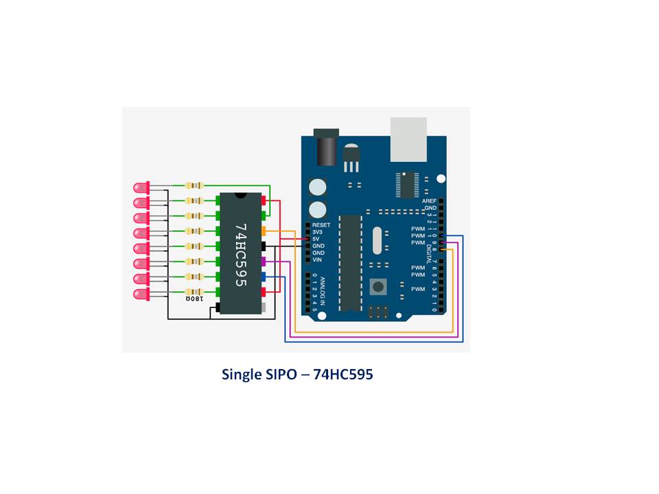
Single SIPO Shift Register, wiring diagram
Used throughout the tutorials
Single SIPO Shift Register, wiring diagram
Comments
Only logged in users can leave comments