Components and supplies
Arduino Uno Rev3
ESP32S
Jumper wires (generic)
Tactile Switch, Top Actuated
Solderless Breadboard Half Size
Resistor 10k ohm
Slide Switch
Apps and platforms
Arduino IDE
Project description
Code
Example 4, ESP 32 - Multiple Switches with Linked External Interrupts
c_cpp
1//
2// A basic ez_switch_lib example - Quick Start, example
3// A
4  sketch configured for four switches sketch.  The sketch will
5// demonstrate how
6  we are able to use external interrupt routines (ISRs)
7// by linking switches
8  to output pins such that when a switch is actuated
9// the associated ISR is triggered.
10//
11  The in-built LED is used to indicate a switch actuation, plus the serial
12// monitor
13  is also used to confirm that the ISR is entered for any switch
14// for which a
15  linked output is defined.
16//
17// For Arduino this is on pin 13 (LED_BUILTIN)
18  and for ESP 32 pin 2. This example is
19// configured for an ESP 32 microcontroller
20//
21//
22  Compatible for both Arduino and ESP 32 microcontrollers, but note:
23//
24//   Not
25  all ESP 32 GPIO pins have a pull_up/pull_down capability.
26//   Those that do
27  not are documented as:
28//     GPIO pins 34-39  these can only be set as input
29  mode and
30//     do not have software enabled pullup or pulldown functions.
31//
32     (Source: espessif)
33//
34// Add your own code where required, eg where you
35  see '...'
36//
37// R D Bentley (Stafford UK)
38//
39// This example and code
40  is in the public domain and may only be
41// used for non-commercial purposes without
42  restriction and
43// without warranty.
44//
45#include <ez_switch_lib.h>
46//...
47#define
48  LED 2 // this is the pin of the internal built LED on ESP 32
49
50#define common_interrupt_pin
51  21 // external (common) interrupt GPIO pin that all linked switches will use
52
53#define
54  max_switches 4
55
56// This array (My_Switches)includes all of the configuration
57  data for the switch(es)
58// to be defined. Switch types and wiring schemes may
59  be mixed.  Each row
60// of the array references the configuration data for each
61  switch to be defined.
62// My_Switches array - rows are defined as:
63// [row][0]
64  - switch type, either 'button_switch' or 'toggle_switch', these are
65//            reserved
66  library macros and may be used without declaration
67// [row][1] - digital pin
68  assigned to the switch
69// [row][2] - circuit type switch is wired as and initialised
70  for via a pinMode call:
71//            This parameter must take one of three values:
72//
73            1. INPUT, or circuit_C1. This requires an external 10k ohm pull down
74  resistor
75//               to be wired in the switch circuit
76//            2.
77  INPUT_PULLUP, or circuit_C2. NO external pull up resistor is required
78//            3.
79  INPUT_PULLDOWN, or circuit_C3. NO external pull down resistor is required
80//
81//
82            Note: INPUT, INPUT_PULLUP, INPUT_PULLDOWN, circuit_C1, circuit_C2 and
83  circuit_C3
84//            are all library reserved macros and may be used without
85  any declaration
86//
87// [row][3] - digital pin number of any linked output pin
88  to this switch
89// [row][4] - If a switch has a linked output pin, this is the
90  value for the pin
91//            to be initialised with (HIGH or LOW) when linked
92  via the function
93//            link_switch_to_output.
94//            NOTE:
95//
96            1. this parameter must be the SAME for ALL switches
97//               linked
98  to the SAME common interrupt pin
99//            2. if the interrupt is triggered
100  on
101//               a. RISING, then this value must be set LOW
102//               b.
103  FALLING, then this value must be set HIGH
104//               c. CHANGE, then this
105  parameter can be either LOW or HIGH
106
107volatile uint8_t My_Switches[max_switches][5]
108  {
109  button_switch, 23, INPUT_PULLDOWN, common_interrupt_pin, HIGH,//switch 0
110
111  toggle_switch, 22, INPUT_PULLUP,   common_interrupt_pin, HIGH,//switch 1
112  button_switch,
113  25, INPUT_PULLUP,                      0,    0,//switch 2, no linked pin for switch
114
115  toggle_switch, 26, INPUT_PULLDOWN, common_interrupt_pin, HIGH //switch 3
116};
117
118volatile
119  const uint8_t interrupt_trigger_type = CHANGE;   // can be RISING, FALLING or CHANGE
120
121volatile
122  uint16_t ISR_count = 0;    // used to show the ISR is being entered
123
124//...
125Switches
126  my_switches(max_switches); // instantiate the class for the required number of switches
127//...
128void
129  setup() {
130  int result;
131  for (uint8_t sw = 0; sw < max_switches; sw++) {
132
133    result = my_switches.add_switch(My_Switches[sw][0], //switch type
134                                    My_Switches[sw][1],
135  //GPIO pin switch connected to
136                                    My_Switches[sw][2]);//circuit
137  type  pinMode
138    if (result < 0) { // error reported  process error
139      //...
140
141    }
142    if (My_Switches[sw][3] != 0) { // there is an output pin to be linked
143
144      result = my_switches.link_switch_to_output(sw, // id of switch to be linked
145
146               My_Switches[sw][3], // GPIO link
147               My_Switches[sw][4]);//
148  initial setting of link
149      if (result < 0) { // error reported  process error
150
151        //...
152      }
153    }
154    attachInterrupt(digitalPinToInterrupt(common_interrupt_pin),
155
156                    switch_ISR,// name of the sketch's ISR handler for switch interrupts
157
158                    interrupt_trigger_type);// how the interrupt will be triggered
159
160  }
161  my_switches.set_debounce(50); // set debounce to 50 millisecs
162  pinMode(LED,
163  OUTPUT); // internal built in LED
164  Serial.begin(115200);
165  //...
166}
167//...
168void
169  loop() {
170  //...
171  do {// keep reading switches each loop
172    for (uint8_t
173  sw = 0; sw < max_switches; sw++) {
174      if (my_switches.read_switch(sw) == switched)
175  {
176        // this switch (sw) has been actuated, so process it
177        //
178  flip status of in built LED to show actuation for all switches
179        // but
180  report switch status to the serial monitor also
181        digitalWrite(LED, digitalRead(LED)
182  ^ 1); // flip in-built LED
183        // now report status of this sw(itch) which
184  has been actuated
185        Serial.print("switch ");
186        Serial.print(sw);
187
188        Serial.print(" (");
189        if (My_Switches[sw][0] == button_switch)Serial.print("button
190  switch)");
191        else Serial.print("toggle switch)");
192        Serial.print("
193  actuated on pin ");
194        Serial.print(My_Switches[sw][1]);        // the
195  pin this sw(itch) is connected to
196        uint8_t linked_pin = My_Switches[sw][3];
197  // the pin this sw(itch) is linked to
198        if (linked_pin != 0) {
199          //
200  this switch has a linked output hthat triggered its ISR
201          // so display
202  the ISR count
203          Serial.print(", ISR linked pin is ");
204          Serial.print(linked_pin);
205
206          Serial.print(", ISR counter = ");
207          Serial.println(ISR_count);
208
209        } else Serial.println();
210        Serial.flush();
211        //...
212
213      }
214      //...
215    }
216    //...
217  } while (true);
218}
219//
220//
221  A common ISR associated with defined switches with linked outputs (standard
222//
223  feature of the ez_switch_ib library).
224// Note that this ISR is a common framework
225  that can be used for all uses
226// of the ez_switch_lib library where switches
227  are linked to output(s) that are
228// configured as external interrupts.  The ISR
229  indicates where end user code
230// should be inserted, depending on the switch
231  type triggering the ISR.
232//
233void switch_ISR() {
234  ISR_count++; //increment
235  ISR counter, for demo only
236  uint8_t switch_id = my_switches.last_switched_id;
237  // switch id of switch currently switched
238  if (my_switches.switches[switch_id].switch_type
239  == button_switch) {
240    // this was a button switch triggering the interrupt
241
242    // *** Button switch processing
243    // *** Put end user code here to deal
244  with this event
245    //...
246  } else {
247    // this was a toggle switch triggering
248  the interrupt
249    // determine if the switch transitioned to 'on' or 'off'
250
251    // and process accordingly
252    if (my_switches.switches[switch_id].switch_status
253  == on) {
254      // *** Toggle switch processing for switch being 'on'
255      //
256  *** Put end user code here to deal with this event
257      //...
258    } else
259  {
260      // *** Toggle switch processing for switch being 'off'
261      // ***
262  Put end user code here to deal with this event
263      //...
264    }
265  }
266
267  // Finish up, with housekeeping tasks...
268  if (interrupt_trigger_type != CHANGE)
269  {
270    // not CHANGE, so we need to reset the interrupt pin
271    bool level;
272
273    // Deal with the switch control structure data first:
274    //   reset interrupt
275  pin (linked output pin) status back to previous value
276    //   (ie invert it),
277  ready for next read if interrupt trigger type is
278    //   RISING or FALLING.
279  If it is CHANGE, then we leave it as is.
280    if (interrupt_trigger_type == RISING)level
281  = LOW; else level = HIGH;
282    my_switches.switches[switch_id].switch_out_pin_status
283  = level;
284
285    // Now deal with the physical interrupt pin (linked output pin)
286  level:
287    //   if the attachInterrupt function trigger parameter is:
288    //
289     "RISING"  then the common interrupt pin must be reset to LOW
290    //     "FALLING"
291  then the common interrupt pin must be reset to HIGH
292    //     "CHANGE"  then
293  we DO NOT reset the common interrupt pin
294    digitalWrite(my_switches.switches[switch_id].switch_out_pin,
295  level);
296  } else {
297    // trigger type is CHANGE, which the code here is a
298  bit more involved!
299    uint8_t ISR_pin = My_Switches[switch_id][3]; // pin defined
300  for this interrupt
301    bool level = my_switches.switches[switch_id].switch_out_pin_status;
302
303    for (uint8_t sw = 0; sw < max_switches; sw++) {
304      if (my_switches.switches[sw].switch_out_pin
305  != 0) {
306        // linked output pin associated with this switch, but only
307
308        // perform update if it is the same pin number as the one
309        //
310  that triggered this interrupt
311        if (my_switches.switches[sw].switch_out_pin
312  == ISR_pin) {
313          // make this switch (sw) same level as the actual switch
314
315          // that triggered the interrupt
316          my_switches.switches[sw].switch_out_pin_status
317  = level;
318        }
319      }
320    }
321  }
322} // End of switch_ISR
323
Quick Start Examples, github
Access the Quick Start Examples form github
Example 4, ESP 32 - Multiple Switches with Linked External Interrupts
c_cpp
1//
2// A basic ez_switch_lib example - Quick Start, example
3// A  sketch configured for four switches sketch.  The sketch will
4// demonstrate how  we are able to use external interrupt routines (ISRs)
5// by linking switches  to output pins such that when a switch is actuated
6// the associated ISR is triggered.
7//  The in-built LED is used to indicate a switch actuation, plus the serial
8// monitor  is also used to confirm that the ISR is entered for any switch
9// for which a  linked output is defined.
10//
11// For Arduino this is on pin 13 (LED_BUILTIN)  and for ESP 32 pin 2. This example is
12// configured for an ESP 32 microcontroller
13//
14//  Compatible for both Arduino and ESP 32 microcontrollers, but note:
15//
16//   Not  all ESP 32 GPIO pins have a pull_up/pull_down capability.
17//   Those that do  not are documented as:
18//     GPIO pins 34-39  these can only be set as input  mode and
19//     do not have software enabled pullup or pulldown functions.
20//     (Source: espessif)
21//
22// Add your own code where required, eg where you  see '...'
23//
24// R D Bentley (Stafford UK)
25//
26// This example and code  is in the public domain and may only be
27// used for non-commercial purposes without  restriction and
28// without warranty.
29//
30#include <ez_switch_lib.h>
31//...
32#define  LED 2 // this is the pin of the internal built LED on ESP 32
33
34#define common_interrupt_pin  21 // external (common) interrupt GPIO pin that all linked switches will use
35
36#define  max_switches 4
37
38// This array (My_Switches)includes all of the configuration  data for the switch(es)
39// to be defined. Switch types and wiring schemes may  be mixed.  Each row
40// of the array references the configuration data for each  switch to be defined.
41// My_Switches array - rows are defined as:
42// [row][0]  - switch type, either 'button_switch' or 'toggle_switch', these are
43//            reserved  library macros and may be used without declaration
44// [row][1] - digital pin  assigned to the switch
45// [row][2] - circuit type switch is wired as and initialised  for via a pinMode call:
46//            This parameter must take one of three values:
47//            1. INPUT, or circuit_C1. This requires an external 10k ohm pull down  resistor
48//               to be wired in the switch circuit
49//            2.  INPUT_PULLUP, or circuit_C2. NO external pull up resistor is required
50//            3.  INPUT_PULLDOWN, or circuit_C3. NO external pull down resistor is required
51//
52//            Note: INPUT, INPUT_PULLUP, INPUT_PULLDOWN, circuit_C1, circuit_C2 and  circuit_C3
53//            are all library reserved macros and may be used without  any declaration
54//
55// [row][3] - digital pin number of any linked output pin  to this switch
56// [row][4] - If a switch has a linked output pin, this is the  value for the pin
57//            to be initialised with (HIGH or LOW) when linked  via the function
58//            link_switch_to_output.
59//            NOTE:
60//            1. this parameter must be the SAME for ALL switches
61//               linked  to the SAME common interrupt pin
62//            2. if the interrupt is triggered  on
63//               a. RISING, then this value must be set LOW
64//               b.  FALLING, then this value must be set HIGH
65//               c. CHANGE, then this  parameter can be either LOW or HIGH
66
67volatile uint8_t My_Switches[max_switches][5]  {
68  button_switch, 23, INPUT_PULLDOWN, common_interrupt_pin, HIGH,//switch 0
69  toggle_switch, 22, INPUT_PULLUP,   common_interrupt_pin, HIGH,//switch 1
70  button_switch,  25, INPUT_PULLUP,                      0,    0,//switch 2, no linked pin for switch
71  toggle_switch, 26, INPUT_PULLDOWN, common_interrupt_pin, HIGH //switch 3
72};
73
74volatile  const uint8_t interrupt_trigger_type = CHANGE;   // can be RISING, FALLING or CHANGE
75
76volatile  uint16_t ISR_count = 0;    // used to show the ISR is being entered
77
78//...
79Switches  my_switches(max_switches); // instantiate the class for the required number of switches
80//...
81void  setup() {
82  int result;
83  for (uint8_t sw = 0; sw < max_switches; sw++) {
84    result = my_switches.add_switch(My_Switches[sw][0], //switch type
85                                    My_Switches[sw][1],  //GPIO pin switch connected to
86                                    My_Switches[sw][2]);//circuit  type  pinMode
87    if (result < 0) { // error reported  process error
88      //...
89    }
90    if (My_Switches[sw][3] != 0) { // there is an output pin to be linked
91      result = my_switches.link_switch_to_output(sw, // id of switch to be linked
92               My_Switches[sw][3], // GPIO link
93               My_Switches[sw][4]);//  initial setting of link
94      if (result < 0) { // error reported  process error
95        //...
96      }
97    }
98    attachInterrupt(digitalPinToInterrupt(common_interrupt_pin),
99                    switch_ISR,// name of the sketch's ISR handler for switch interrupts
100                    interrupt_trigger_type);// how the interrupt will be triggered
101  }
102  my_switches.set_debounce(50); // set debounce to 50 millisecs
103  pinMode(LED,  OUTPUT); // internal built in LED
104  Serial.begin(115200);
105  //...
106}
107//...
108void  loop() {
109  //...
110  do {// keep reading switches each loop
111    for (uint8_t  sw = 0; sw < max_switches; sw++) {
112      if (my_switches.read_switch(sw) == switched)  {
113        // this switch (sw) has been actuated, so process it
114        //  flip status of in built LED to show actuation for all switches
115        // but  report switch status to the serial monitor also
116        digitalWrite(LED, digitalRead(LED)  ^ 1); // flip in-built LED
117        // now report status of this sw(itch) which  has been actuated
118        Serial.print("switch ");
119        Serial.print(sw);
120        Serial.print(" (");
121        if (My_Switches[sw][0] == button_switch)Serial.print("button  switch)");
122        else Serial.print("toggle switch)");
123        Serial.print("  actuated on pin ");
124        Serial.print(My_Switches[sw][1]);        // the  pin this sw(itch) is connected to
125        uint8_t linked_pin = My_Switches[sw][3];  // the pin this sw(itch) is linked to
126        if (linked_pin != 0) {
127          //  this switch has a linked output hthat triggered its ISR
128          // so display  the ISR count
129          Serial.print(", ISR linked pin is ");
130          Serial.print(linked_pin);
131          Serial.print(", ISR counter = ");
132          Serial.println(ISR_count);
133        } else Serial.println();
134        Serial.flush();
135        //...
136      }
137      //...
138    }
139    //...
140  } while (true);
141}
142//
143//  A common ISR associated with defined switches with linked outputs (standard
144//  feature of the ez_switch_ib library).
145// Note that this ISR is a common framework  that can be used for all uses
146// of the ez_switch_lib library where switches  are linked to output(s) that are
147// configured as external interrupts.  The ISR  indicates where end user code
148// should be inserted, depending on the switch  type triggering the ISR.
149//
150void switch_ISR() {
151  ISR_count++; //increment  ISR counter, for demo only
152  uint8_t switch_id = my_switches.last_switched_id;  // switch id of switch currently switched
153  if (my_switches.switches[switch_id].switch_type  == button_switch) {
154    // this was a button switch triggering the interrupt
155    // *** Button switch processing
156    // *** Put end user code here to deal  with this event
157    //...
158  } else {
159    // this was a toggle switch triggering  the interrupt
160    // determine if the switch transitioned to 'on' or 'off'
161    // and process accordingly
162    if (my_switches.switches[switch_id].switch_status  == on) {
163      // *** Toggle switch processing for switch being 'on'
164      //  *** Put end user code here to deal with this event
165      //...
166    } else  {
167      // *** Toggle switch processing for switch being 'off'
168      // ***  Put end user code here to deal with this event
169      //...
170    }
171  }
172  // Finish up, with housekeeping tasks...
173  if (interrupt_trigger_type != CHANGE)  {
174    // not CHANGE, so we need to reset the interrupt pin
175    bool level;
176    // Deal with the switch control structure data first:
177    //   reset interrupt  pin (linked output pin) status back to previous value
178    //   (ie invert it),  ready for next read if interrupt trigger type is
179    //   RISING or FALLING.  If it is CHANGE, then we leave it as is.
180    if (interrupt_trigger_type == RISING)level  = LOW; else level = HIGH;
181    my_switches.switches[switch_id].switch_out_pin_status  = level;
182
183    // Now deal with the physical interrupt pin (linked output pin)  level:
184    //   if the attachInterrupt function trigger parameter is:
185    //     "RISING"  then the common interrupt pin must be reset to LOW
186    //     "FALLING"  then the common interrupt pin must be reset to HIGH
187    //     "CHANGE"  then  we DO NOT reset the common interrupt pin
188    digitalWrite(my_switches.switches[switch_id].switch_out_pin,  level);
189  } else {
190    // trigger type is CHANGE, which the code here is a  bit more involved!
191    uint8_t ISR_pin = My_Switches[switch_id][3]; // pin defined  for this interrupt
192    bool level = my_switches.switches[switch_id].switch_out_pin_status;
193    for (uint8_t sw = 0; sw < max_switches; sw++) {
194      if (my_switches.switches[sw].switch_out_pin  != 0) {
195        // linked output pin associated with this switch, but only
196        // perform update if it is the same pin number as the one
197        //  that triggered this interrupt
198        if (my_switches.switches[sw].switch_out_pin  == ISR_pin) {
199          // make this switch (sw) same level as the actual switch
200          // that triggered the interrupt
201          my_switches.switches[sw].switch_out_pin_status  = level;
202        }
203      }
204    }
205  }
206} // End of switch_ISR
207
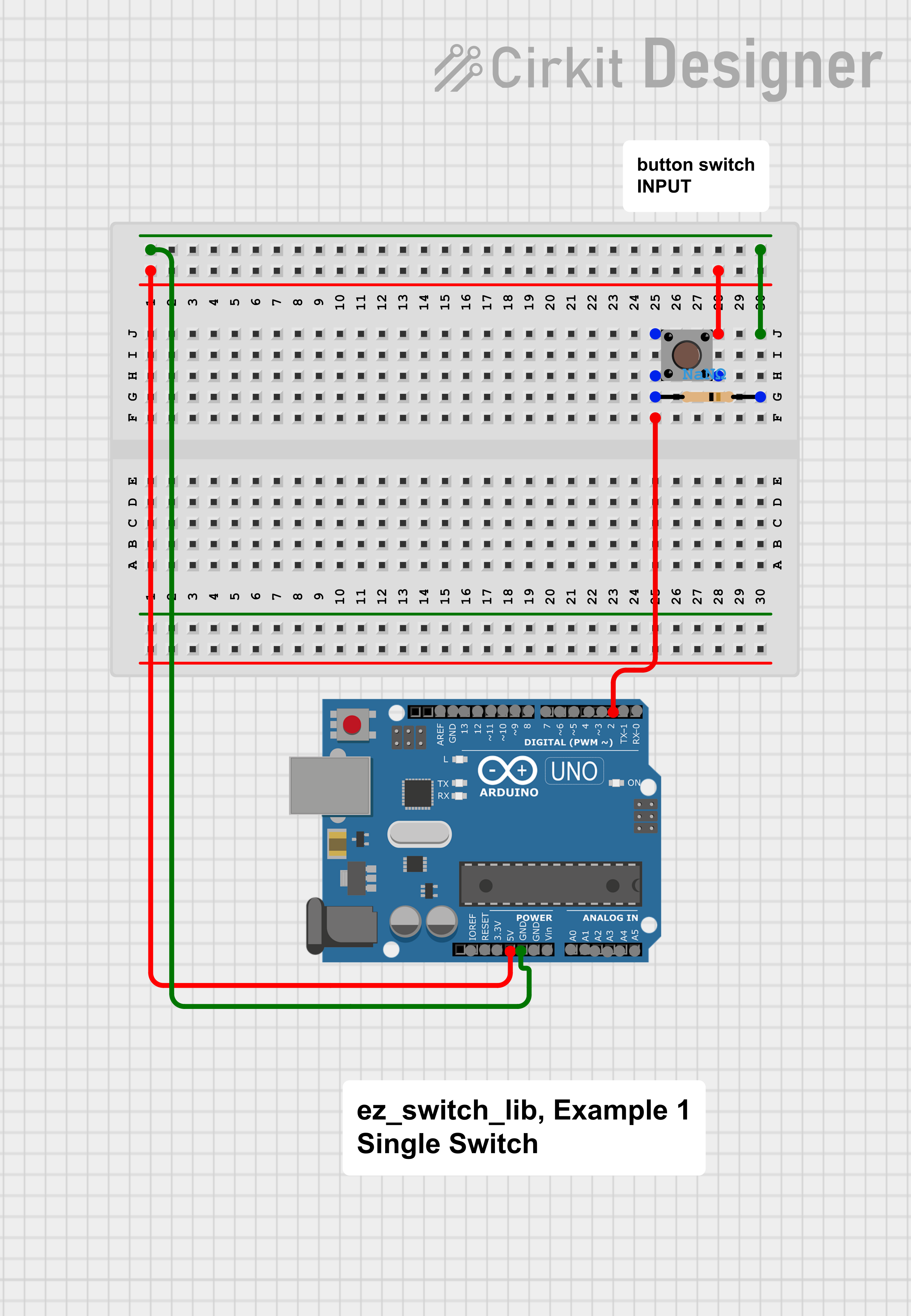
Example 1 - Arduino - Single Switch
c_cpp
1//
2// A basic ez_switch_lib example - Quick Start, example 1
3//  A single switch sketch designed to flip the status of the in-built LED
4// for  Arduino this is on pin 13 (LED_BUILTIN) and for ESP 32 pin 2 This example is
5//  configured for an Arduino microcontroller
6//
7// Compatible for both Arduino  and ESP 32 microcontrollers
8//
9// Add your own code where required, eg where  you see '...'
10//
11// R D Bentley (Stafford UK)
12//
13// This example and  code is in the public domain and may only be
14// used for non-commercial purposes  without restriction and
15// without warranty.
16//
17#include <ez_switch_lib.h>
18//...
19#define  LED LED_BUILTIN // built in LED on Arduino boards
20int switch_id; // use to record  switch id we add to the class
21
22//...
23Switches my_switch(1); // create class  size for 1 switch
24//...
25void setup() {
26  // create switch with a 10k ohm  external pull down resistor - INPUT pinMode parameter
27  switch_id = my_switch.add_switch(button_switch,//  switch type
28                                   2,            // pin switch connected  to
29                                   INPUT);       // circuit type  pinMode
30  if (switch_id < 0) { // error reported  process error
31    //...
32  }
33  my_switch.set_debounce(50); // set debounce to 50 millisecs
34  pinMode(LED,  OUTPUT); // internal built in LED
35  //...
36}
37//...
38void loop() {
39  //...
40  do {
41    if (my_switch.read_switch(switch_id) == switched) {
42      // this switch (swith_id) has been actuated, so process it
43      digitalWrite(LED,  digitalRead(LED) ^ 1); // flip status of in built LED to show actuation
44      //...
45    }
46    //...
47  } while (true);
48}
49
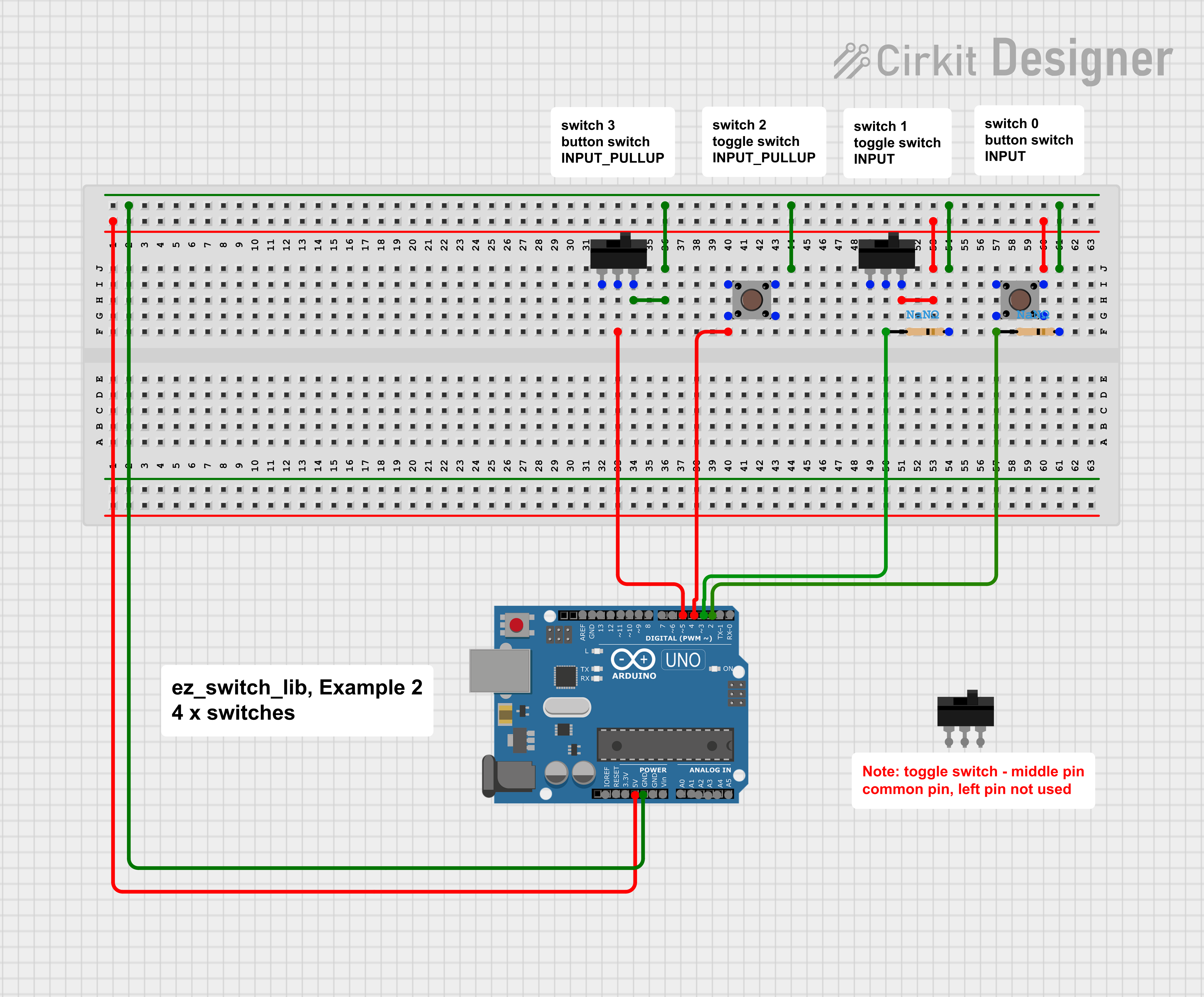
Example 2, Arduino - Multiple Switches
c_cpp
1//
2// A basic ez_switch_lib example - Quick Start, example 2
3//  A sketch configured for four switches sketch to flip the status of the in-built  LED
4// for Arduino this is on pin 13 (LED_BUILTIN) and for ESP 32 pin 2. This  example is
5// configured for an Arduino microcontroller
6//
7// Compatible  for both Arduino and ESP 32 microcontrollers
8//
9// Add your own code where  required, eg where you see '...'
10//
11// R D Bentley (Stafford UK)
12//
13//  This example and code is in the public domain and may only be
14// used for non-commercial  purposes without restriction and
15// without warranty.
16//
17#include <ez_switch_lib.h>
18//...
19#define  LED LED_BUILTIN // built in LED on Arduino boards
20
21#define max_switches 4
22uint8_t  My_Switches[max_switches][3] {
23  button_switch, 2, INPUT,        // switch 0
24  toggle_switch, 3, INPUT,        // switch 1
25  button_switch, 4, INPUT_PULLUP,  // switch 2
26  toggle_switch, 5, INPUT_PULLUP  // switch 3
27};
28//...
29Switches  my_switches(max_switches);
30//...
31void setup() {
32  int result;
33  for  (uint8_t sw = 0; sw < max_switches; sw++) {
34    result = my_switches.add_switch(My_Switches[sw][0],  //switch type
35                                    My_Switches[sw][1], //pin switch  connected to
36                                    My_Switches[sw][2]);//circuit  type  pinMode
37    if (result < 0) { // error reported  process error
38      //...
39    }
40  }
41  my_switches.set_debounce(50); // set debounce to 50 millisecs
42  pinMode(LED, OUTPUT); // internal built in LED
43  //...
44}
45//...
46void  loop() {
47  //...
48  do {
49    for (uint8_t sw = 0; sw < max_switches; sw++)  {
50      if (my_switches.read_switch(sw) == switched) {
51        // this switch  (sw) has been actuated, so process it
52        digitalWrite(LED, digitalRead(LED)  ^ 1); // flip status of in built LED to show actuation
53        //...
54      }
55      //...
56    }
57    //...
58  } while (true);
59}
60
Example 1 - Arduino - Single Switch
c_cpp
1//
2// A basic ez_switch_lib example - Quick Start, example 1
3//   A single switch sketch designed to flip the status of the in-built LED
4// for   Arduino this is on pin 13 (LED_BUILTIN) and for ESP 32 pin 2 This example is
5//   configured for an Arduino microcontroller
6//
7// Compatible for both Arduino   and ESP 32 microcontrollers
8//
9// Add your own code where required, eg where   you see '...'
10//
11// R D Bentley (Stafford UK)
12//
13// This example and   code is in the public domain and may only be
14// used for non-commercial purposes   without restriction and
15// without warranty.
16//
17#include <ez_switch_lib.h>
18//...
19#define   LED LED_BUILTIN // built in LED on Arduino boards
20int switch_id; // use to record   switch id we add to the class
21
22//...
23Switches my_switch(1); // create class   size for 1 switch
24//...
25void setup() {
26  // create switch with a 10k ohm   external pull down resistor - INPUT pinMode parameter
27  switch_id = my_switch.add_switch(button_switch,//   switch type
28                                   2,            // pin switch connected   to
29                                   INPUT);       // circuit type  pinMode
30   if (switch_id < 0) { // error reported  process error
31    //...
32  }
33   my_switch.set_debounce(50); // set debounce to 50 millisecs
34  pinMode(LED,   OUTPUT); // internal built in LED
35  //...
36}
37//...
38void loop() {
39   //...
40  do {
41    if (my_switch.read_switch(switch_id) == switched) {
42       // this switch (swith_id) has been actuated, so process it
43      digitalWrite(LED,   digitalRead(LED) ^ 1); // flip status of in built LED to show actuation
44      //...
45     }
46    //...
47  } while (true);
48}
49
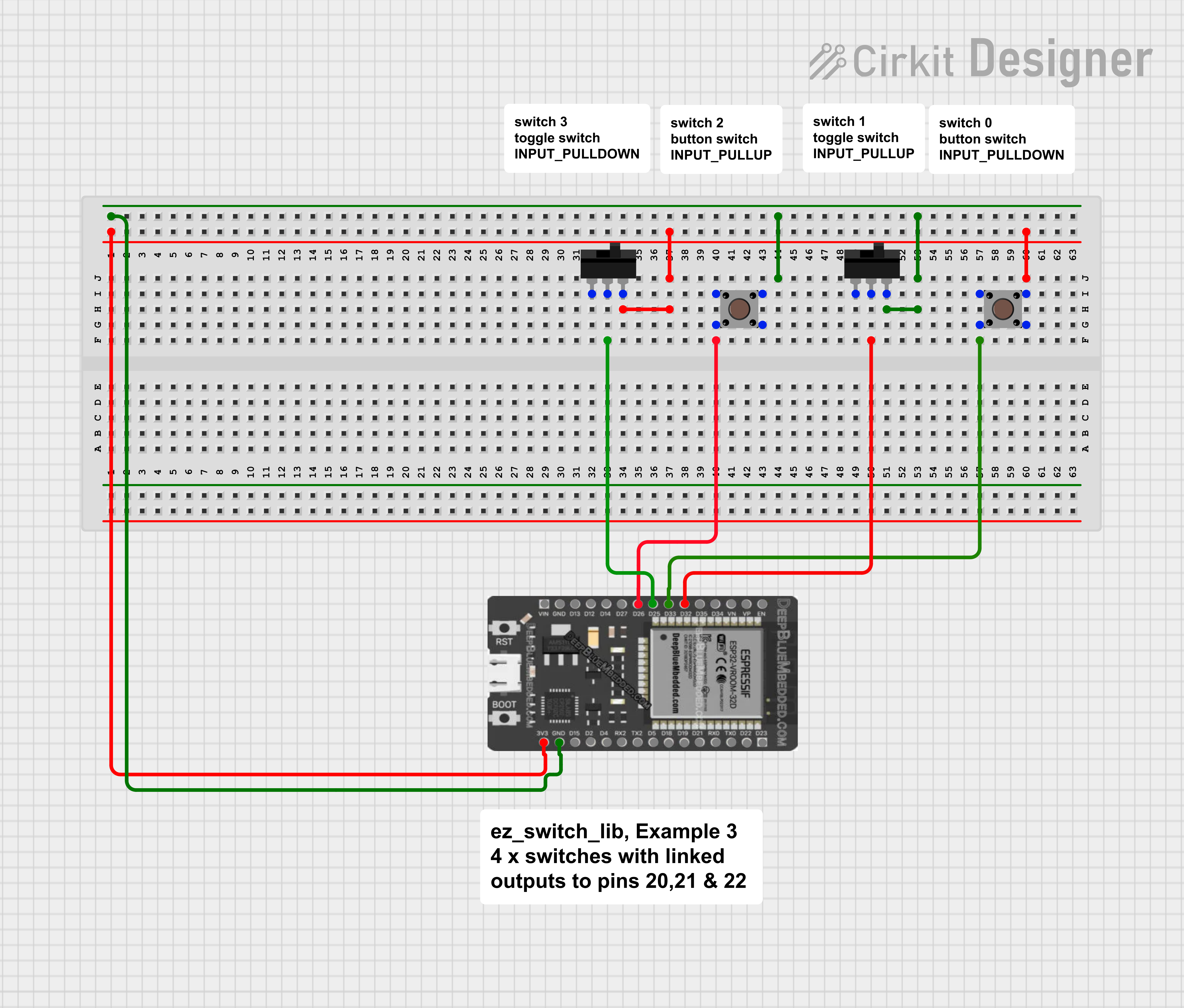
Example 3, ESP 32 - Multiple Switch with Linked Outputs
c_cpp
1//
2// A basic ez_switch_lib example - Quick Start, example 3
3//  A sketch configured for four switches sketch.  The sketch will:
4// 1. flip the  status of the in-built LED for all switch actuations
5// 2. flip the linked output  pins defined for 3 of the switches. The serial
6//    monitor is used to show  that the linked pins are flipped each time
7//    its associated switch is actuated.
8//
9//  For Arduino this is on pin 13 (LED_BUILTIN) and for ESP 32 pin 2. This example is
10//  configured for an ESP 32 microcontroller
11//
12// Compatible for both Arduino  and ESP 32 microcontrollers, but note:
13//
14//   Not all ESP 32 GPIO pins have  a pull_up/pull_down capability.
15//   Those that do not are documented as:
16//     GPIO pins 34-39  these can only be set as input mode and
17//     do not have  software enabled pullup or pulldown functions.
18//     (Source: espessif)
19//
20//  Add your own code where required, eg where you see '...'
21//
22// R D Bentley  (Stafford UK)
23//
24// This example and code is in the public domain and may  only be
25// used for non-commercial purposes without restriction and
26// without  warranty.
27//
28#include <ez_switch_lib.h>
29//...
30#define LED 2 // this  is the pin of the internal built LED on ESP 32
31
32#define max_switches 4
33uint8_t  My_Switches[max_switches][5] {
34  button_switch, 23, INPUT_PULLDOWN, 21,  LOW,  // switch 0, start with linked pin LOW
35  toggle_switch, 22, INPUT_PULLUP,   19,  HIGH, // switch 1, start with linked pin HIGH
36  button_switch, 25, INPUT_PULLUP,    0,    0, // switch 2, no linked  pin on this switch
37  toggle_switch, 26,  INPUT_PULLDOWN, 18,  LOW  // switch 3, start with linked pin LOW
38};
39//...
40Switches  my_switches(max_switches); // instantiate the class for the required number of switches
41//...
42void  setup() {
43  int result;
44  for (uint8_t sw = 0; sw < max_switches; sw++) {
45    result = my_switches.add_switch(My_Switches[sw][0], //switch type
46                                    My_Switches[sw][1],  //GPIO pin switch connected to
47                                    My_Switches[sw][2]);//circuit  type  pinMode
48    if (result < 0) { // error reported  process error
49      //...
50    }
51    if (My_Switches[sw][3] != 0) { // there is an output pin to be linked
52      result = my_switches.link_switch_to_output(sw, // id of switch to be linked
53               My_Switches[sw][3], // GPIO link
54               My_Switches[sw][4]);//  initial setting of link
55      if (result < 0) { // error reported  process error
56        //...
57      }
58    }
59  }
60  my_switches.set_debounce(50); // set  debounce to 50 millisecs
61  pinMode(LED, OUTPUT); // internal built in LED
62  Serial.begin(115200); // open serial monitor
63  //...
64}
65//...
66void  loop() {
67  //...
68  do {// keep reading switches each loop
69    for (uint8_t  sw = 0; sw < max_switches; sw++) {
70      if (my_switches.read_switch(sw) == switched)  {
71        // this switch (sw) has been actuated, so process it
72        //  flip status of in built LED to show actuation for all switches
73        // but  report switch status to the serial monitor also
74        digitalWrite(LED, digitalRead(LED)  ^ 1); // flip in-built LED
75        // now report status of this sw(itch) which  has been actuated
76        Serial.print("switch ");
77        Serial.print(sw);
78        Serial.print(" (");
79        if (My_Switches[sw][0] == button_switch)Serial.print("button  switch)"); else
80        Serial.print("toggle switch)");
81        Serial.print("  actuated on pin ");
82        Serial.print(My_Switches[sw][1]);        // the  pin this sw(itch) is connected to
83        uint8_t linked_pin = My_Switches[sw][3];  // the pin this sw(itch) is linked to
84        if (linked_pin != 0) {
85          //  this switch has a linked output so read that pins current status
86          //  and report
87          bool pin_status = digitalRead(linked_pin);
88          Serial.print(",  linked pin is ");
89          Serial.print(linked_pin);
90          Serial.print(",  current status is ");
91          if (pin_status == HIGH)Serial.println("HIGH");  else Serial.println("LOW");
92        } else {
93          Serial.println(",  no linked pin");
94        }
95        Serial.flush();
96        //...
97      }
98      //...
99    }
100    //...
101  } while (true);
102}
103
Quick Start Examples, github
Access the Quick Start Examples form github
Example 3, ESP 32 - Multiple Switch with Linked Outputs
c_cpp
1//
2// A basic ez_switch_lib example - Quick Start, example 3
3//
4  A sketch configured for four switches sketch.  The sketch will:
5// 1. flip the
6  status of the in-built LED for all switch actuations
7// 2. flip the linked output
8  pins defined for 3 of the switches. The serial
9//    monitor is used to show
10  that the linked pins are flipped each time
11//    its associated switch is actuated.
12//
13//
14  For Arduino this is on pin 13 (LED_BUILTIN) and for ESP 32 pin 2. This example is
15//
16  configured for an ESP 32 microcontroller
17//
18// Compatible for both Arduino
19  and ESP 32 microcontrollers, but note:
20//
21//   Not all ESP 32 GPIO pins have
22  a pull_up/pull_down capability.
23//   Those that do not are documented as:
24//
25     GPIO pins 34-39  these can only be set as input mode and
26//     do not have
27  software enabled pullup or pulldown functions.
28//     (Source: espessif)
29//
30//
31  Add your own code where required, eg where you see '...'
32//
33// R D Bentley
34  (Stafford UK)
35//
36// This example and code is in the public domain and may
37  only be
38// used for non-commercial purposes without restriction and
39// without
40  warranty.
41//
42#include <ez_switch_lib.h>
43//...
44#define LED 2 // this
45  is the pin of the internal built LED on ESP 32
46
47#define max_switches 4
48uint8_t
49  My_Switches[max_switches][5] {
50  button_switch, 23, INPUT_PULLDOWN, 21,  LOW,
51  // switch 0, start with linked pin LOW
52  toggle_switch, 22, INPUT_PULLUP,   19,
53  HIGH, // switch 1, start with linked pin HIGH
54  button_switch, 25, INPUT_PULLUP,
55    0,    0, // switch 2, no linked  pin on this switch
56  toggle_switch, 26,
57  INPUT_PULLDOWN, 18,  LOW  // switch 3, start with linked pin LOW
58};
59//...
60Switches
61  my_switches(max_switches); // instantiate the class for the required number of switches
62//...
63void
64  setup() {
65  int result;
66  for (uint8_t sw = 0; sw < max_switches; sw++) {
67
68    result = my_switches.add_switch(My_Switches[sw][0], //switch type
69                                    My_Switches[sw][1],
70  //GPIO pin switch connected to
71                                    My_Switches[sw][2]);//circuit
72  type  pinMode
73    if (result < 0) { // error reported  process error
74      //...
75
76    }
77    if (My_Switches[sw][3] != 0) { // there is an output pin to be linked
78
79      result = my_switches.link_switch_to_output(sw, // id of switch to be linked
80
81               My_Switches[sw][3], // GPIO link
82               My_Switches[sw][4]);//
83  initial setting of link
84      if (result < 0) { // error reported  process error
85
86        //...
87      }
88    }
89  }
90  my_switches.set_debounce(50); // set
91  debounce to 50 millisecs
92  pinMode(LED, OUTPUT); // internal built in LED
93
94  Serial.begin(115200); // open serial monitor
95  //...
96}
97//...
98void
99  loop() {
100  //...
101  do {// keep reading switches each loop
102    for (uint8_t
103  sw = 0; sw < max_switches; sw++) {
104      if (my_switches.read_switch(sw) == switched)
105  {
106        // this switch (sw) has been actuated, so process it
107        //
108  flip status of in built LED to show actuation for all switches
109        // but
110  report switch status to the serial monitor also
111        digitalWrite(LED, digitalRead(LED)
112  ^ 1); // flip in-built LED
113        // now report status of this sw(itch) which
114  has been actuated
115        Serial.print("switch ");
116        Serial.print(sw);
117
118        Serial.print(" (");
119        if (My_Switches[sw][0] == button_switch)Serial.print("button
120  switch)"); else
121        Serial.print("toggle switch)");
122        Serial.print("
123  actuated on pin ");
124        Serial.print(My_Switches[sw][1]);        // the
125  pin this sw(itch) is connected to
126        uint8_t linked_pin = My_Switches[sw][3];
127  // the pin this sw(itch) is linked to
128        if (linked_pin != 0) {
129          //
130  this switch has a linked output so read that pins current status
131          //
132  and report
133          bool pin_status = digitalRead(linked_pin);
134          Serial.print(",
135  linked pin is ");
136          Serial.print(linked_pin);
137          Serial.print(",
138  current status is ");
139          if (pin_status == HIGH)Serial.println("HIGH");
140  else Serial.println("LOW");
141        } else {
142          Serial.println(",
143  no linked pin");
144        }
145        Serial.flush();
146        //...
147      }
148
149      //...
150    }
151    //...
152  } while (true);
153}
154
Example 2, Arduino - Multiple Switches
c_cpp
1//
2// A basic ez_switch_lib example - Quick Start, example 2
3//
4  A sketch configured for four switches sketch to flip the status of the in-built
5  LED
6// for Arduino this is on pin 13 (LED_BUILTIN) and for ESP 32 pin 2. This
7  example is
8// configured for an Arduino microcontroller
9//
10// Compatible
11  for both Arduino and ESP 32 microcontrollers
12//
13// Add your own code where
14  required, eg where you see '...'
15//
16// R D Bentley (Stafford UK)
17//
18//
19  This example and code is in the public domain and may only be
20// used for non-commercial
21  purposes without restriction and
22// without warranty.
23//
24#include <ez_switch_lib.h>
25//...
26#define
27  LED LED_BUILTIN // built in LED on Arduino boards
28
29#define max_switches 4
30uint8_t
31  My_Switches[max_switches][3] {
32  button_switch, 2, INPUT,        // switch 0
33
34  toggle_switch, 3, INPUT,        // switch 1
35  button_switch, 4, INPUT_PULLUP,
36  // switch 2
37  toggle_switch, 5, INPUT_PULLUP  // switch 3
38};
39//...
40Switches
41  my_switches(max_switches);
42//...
43void setup() {
44  int result;
45  for
46  (uint8_t sw = 0; sw < max_switches; sw++) {
47    result = my_switches.add_switch(My_Switches[sw][0],
48  //switch type
49                                    My_Switches[sw][1], //pin switch
50  connected to
51                                    My_Switches[sw][2]);//circuit
52  type  pinMode
53    if (result < 0) { // error reported  process error
54      //...
55
56    }
57  }
58  my_switches.set_debounce(50); // set debounce to 50 millisecs
59
60  pinMode(LED, OUTPUT); // internal built in LED
61  //...
62}
63//...
64void
65  loop() {
66  //...
67  do {
68    for (uint8_t sw = 0; sw < max_switches; sw++)
69  {
70      if (my_switches.read_switch(sw) == switched) {
71        // this switch
72  (sw) has been actuated, so process it
73        digitalWrite(LED, digitalRead(LED)
74  ^ 1); // flip status of in built LED to show actuation
75        //...
76      }
77
78      //...
79    }
80    //...
81  } while (true);
82}
83
Downloadable files
Example 2, Multiple Switches
Example 2, Multiple Switches
Example 1, Single Switch
Example 1, Single Switch
Example 3, Multiple Switches with Linked Outputs
Example 3, Multiple Switches with Linked Outputs
Example 1, Single Switch
Example 1, Single Switch
Example 3, Multiple Switches with Linked Outputs
Example 3, Multiple Switches with Linked Outputs
Example 2, Multiple Switches
Example 2, Multiple Switches
Example 4, Multiple Switches with Linked Outputs and ISR
Example 4, Multiple Switches with Linked Outputs and ISR

Comments
Only logged in users can leave comments