Autobraking Rc Car
Create your own phone controlled smart car !!!
Devices & Components
Arduino Uno Rev3
Mini Breadboard
Solderless Breadboard Half Size
Portable Charger
DC Gearbox Motor 3-6V
Battery Holder, 9V
9V battery (generic)
2 in. Medium Duty Gray TPR Swivel Plate Caster
Adafruit Dual H-Bridge Motor Driver
HC-05 Bluetooth Module
Jumper wires (generic)
Hardware & Tools
Hot glue gun (generic)
Software & Tools
Arduino IDE
MIT App Inventor 2
Project description
Code
Remote Controlled car with emergency brake
arduino
Remember to disconnect the Bluetooth module when uploading code to the Arduino board.
Remote Controlled car with emergency brake
arduino
Remember to disconnect the Bluetooth module when uploading code to the Arduino board.
Downloadable files
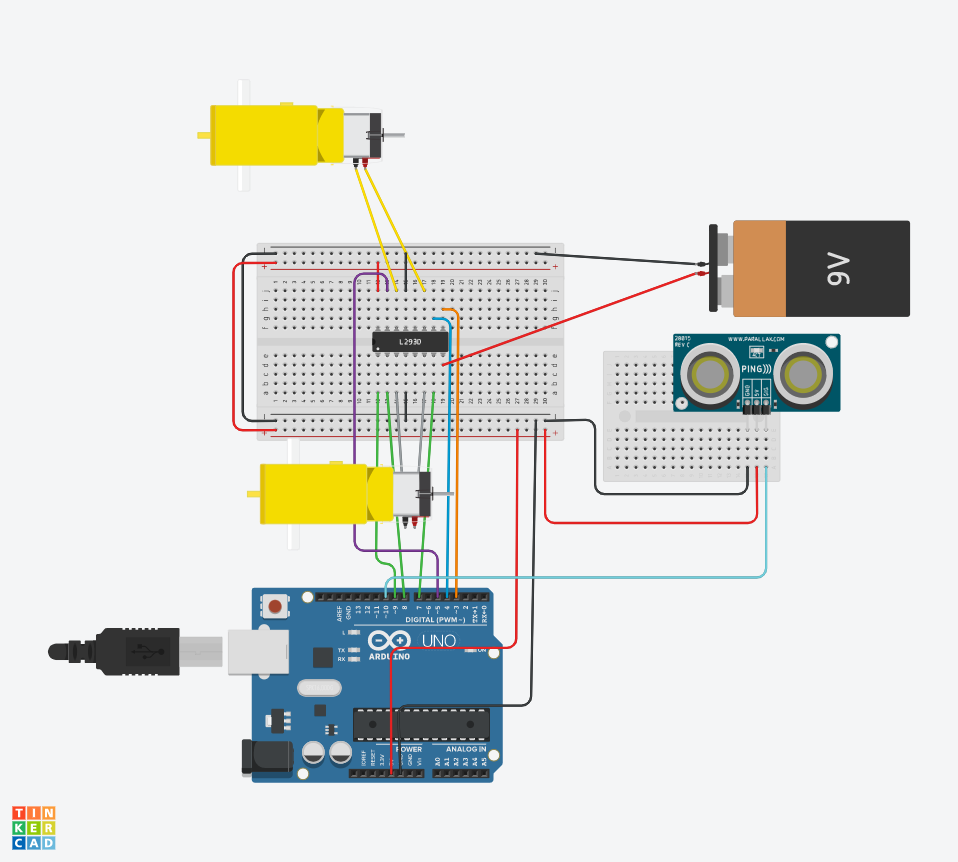
Schematic
Attaching the jumper cables: Connect 5v on the arduino to the breadboard Connect GND on the arduino to the breadboard Connect enable1,2 to digital pin 11 Connect input 1 to digital pin 8 Connect output 1 to the negative of the hobby gearmotor Connect GND(4) to ground on the breadboard Connect output 2 to positive of the hobby gearmotor Connect input 2 to digital pin 7 Connect Vcc 2 to 9v battery Connect enable 3,4 to digital pin 3 Connect input 3 to digital pin 4 Connect output 3 to the positive of the second hobby gearmotor Connect GND(13) to ground on the breadboard Connect output 4 to the negative of the second hobby gearmotor Connect Vcc 1 to 5v on the breadboard Connect input 4 to digital pin 5 Connecting the Bluetooth module: Connect Vcc to the power on the breadboard Connect GND to the ground on the breadboard Connect RXD to digital pin 1 Connect TXD to digital pin 0 Connecting the Ultrasonic Range Finder: Connect GND to ground on the breadboard Connect 5v to power on the breadboard Connect echo to digital pin 10 Connect trig to digital pin 9
Schematic
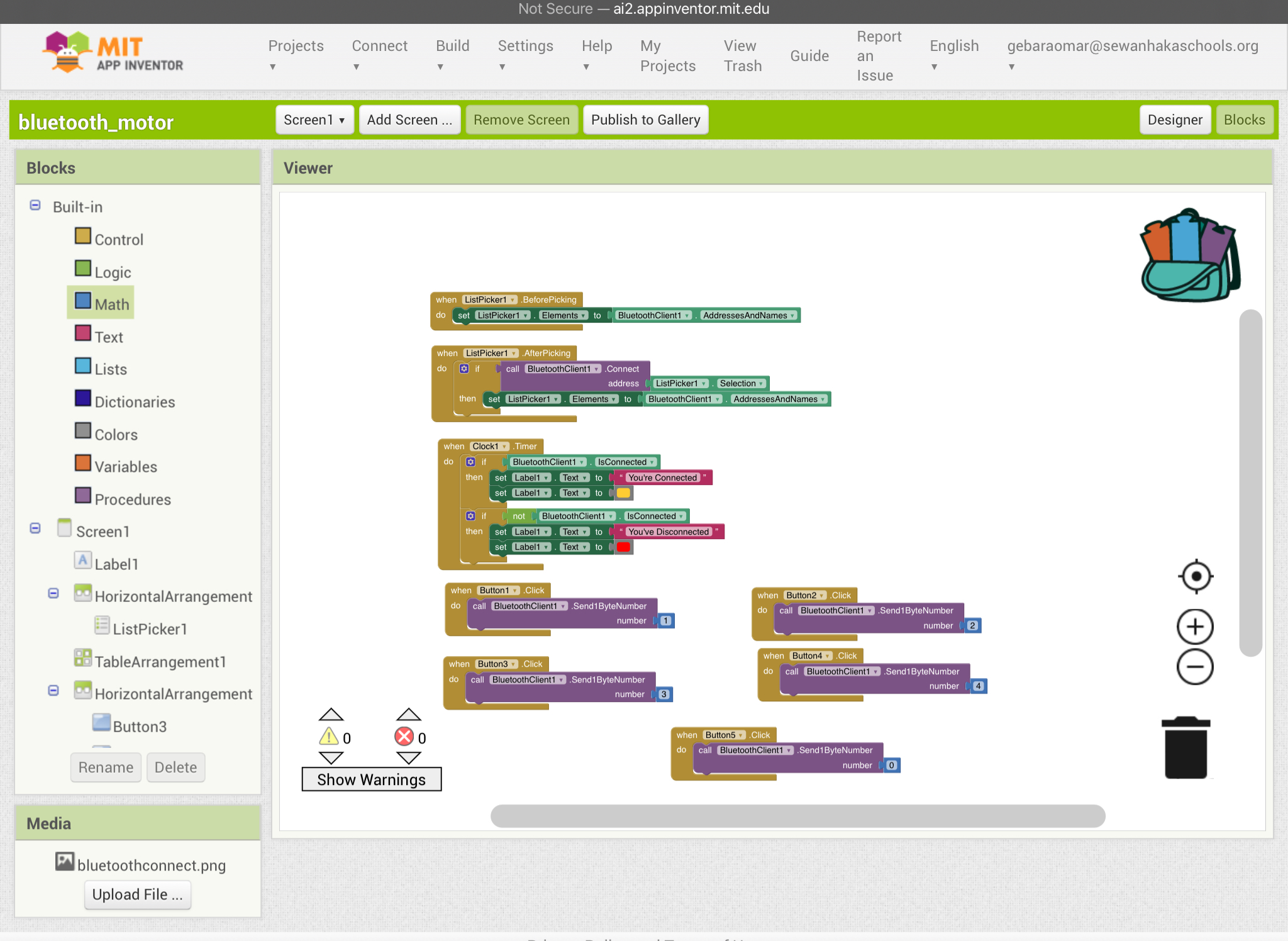
MIT App
Setting up the app: To set up this app follow the block commands shown in the diagram
MIT App
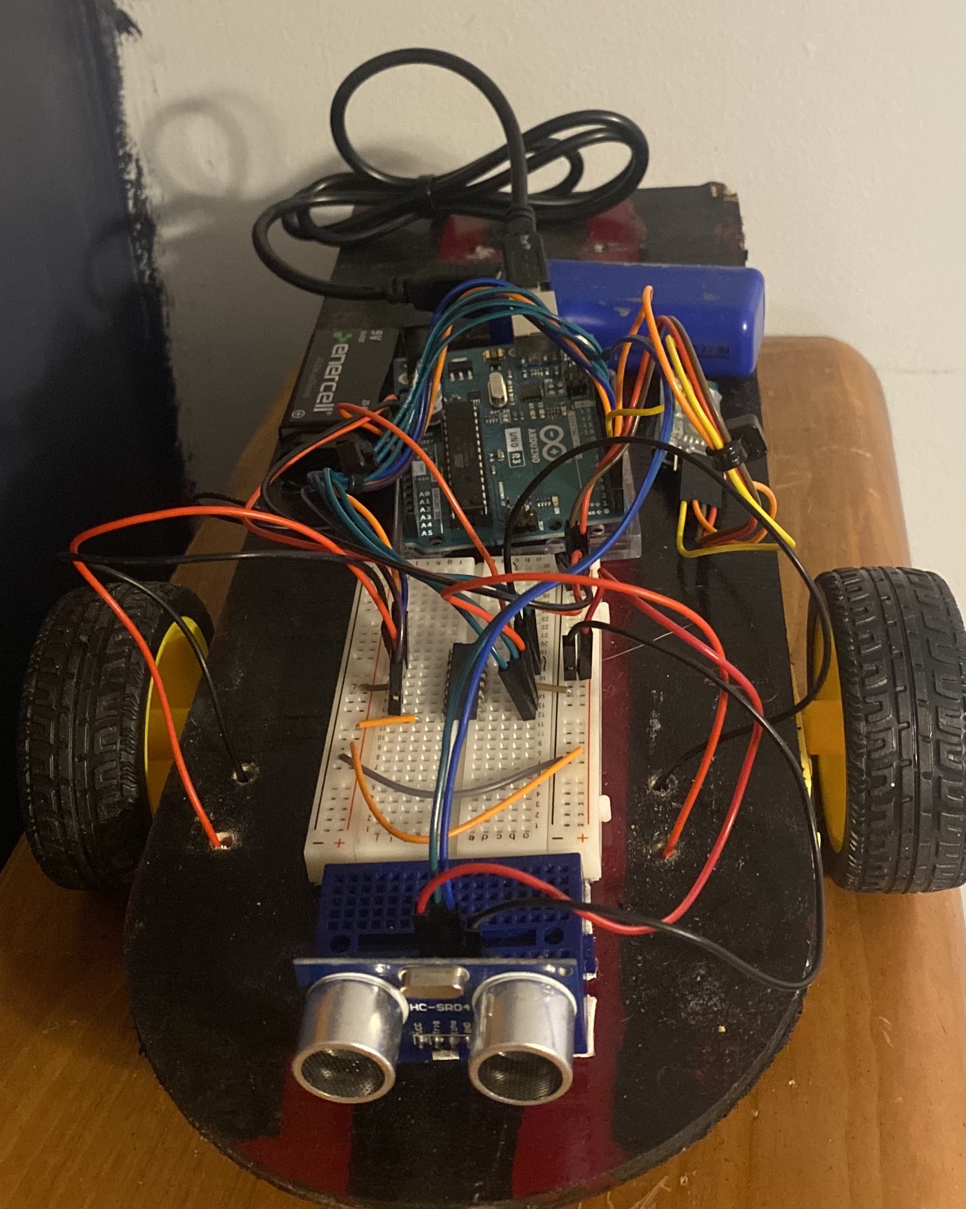
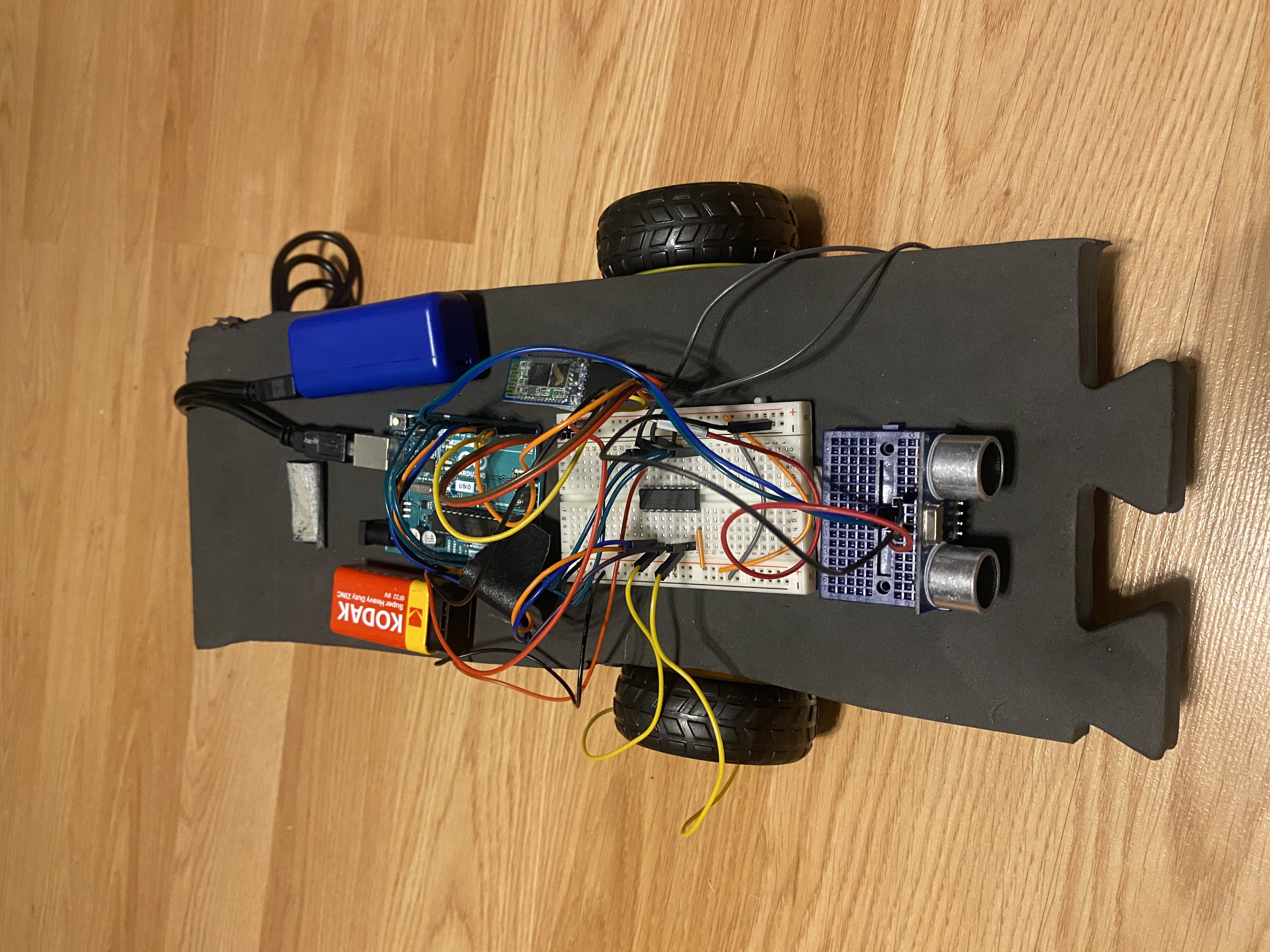
Final result
1)Glue the hobby gear motors to the bottom of the base of the car 2)Drill the caster wheel to the back of the base 3)Attach all the breadboards and arduino to the base
Final result
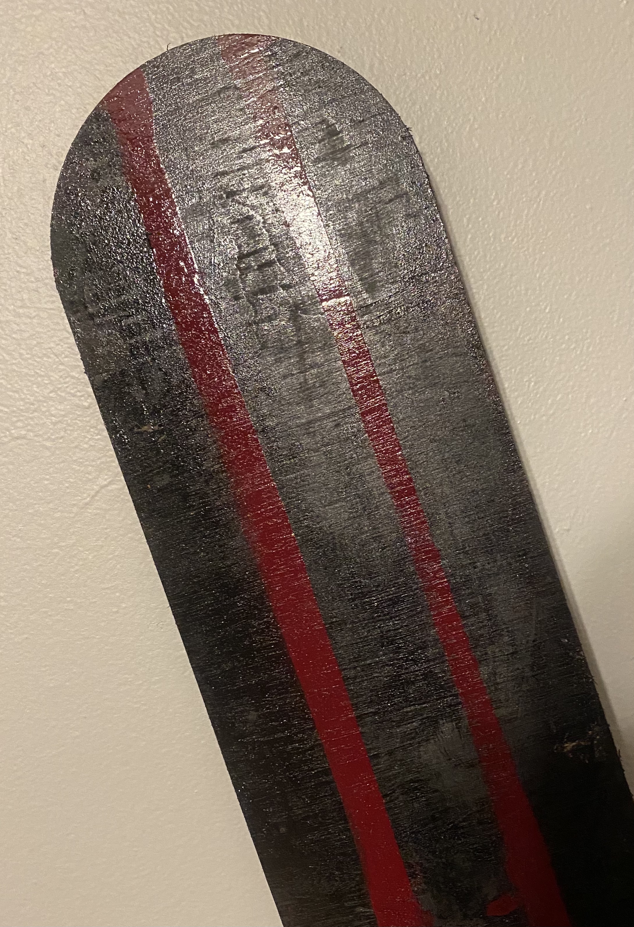
Style
Even though this is not an essential component of this project I chose to paint the wooden base that I decided to use. I did this to add my aspect to this project.
Style
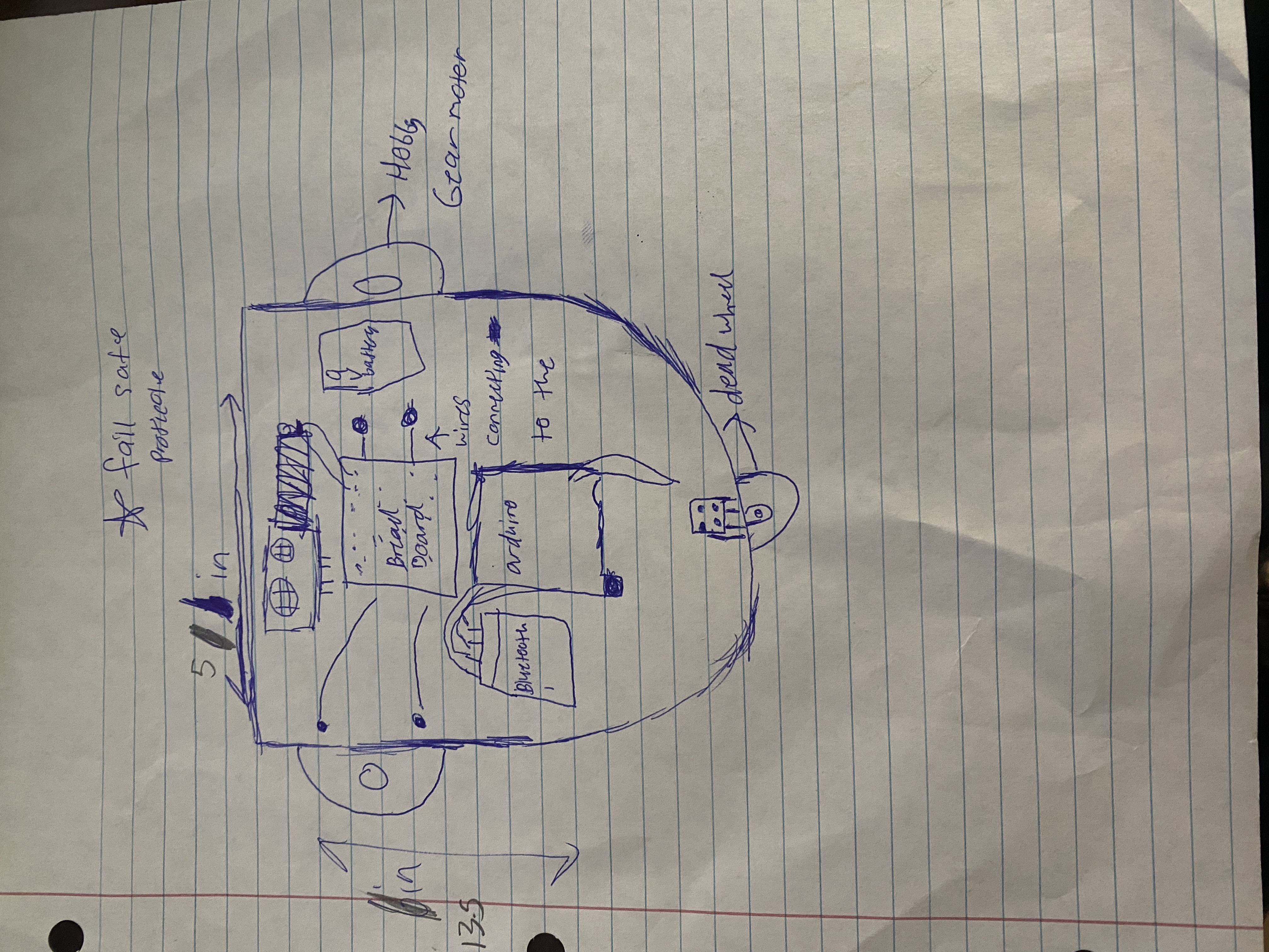
Sketch
It is good draw a project for a physical visualization and to label each component for clarity.
Sketch
Style
Even though this is not an essential component of this project I chose to paint the wooden base that I decided to use. I did this to add my aspect to this project.
Style
Prototype
Before building the final product of your project it is important to prototype the project. Through building this project on a smaller scale or a cheaper material you can adequately size and organize each part of the project.
Prototype
Final result
1)Glue the hobby gear motors to the bottom of the base of the car 2)Drill the caster wheel to the back of the base 3)Attach all the breadboards and arduino to the base
Final result
MIT App
Setting up the app: To set up this app follow the block commands shown in the diagram
MIT App
Schematic
Attaching the jumper cables: Connect 5v on the arduino to the breadboard Connect GND on the arduino to the breadboard Connect enable1,2 to digital pin 11 Connect input 1 to digital pin 8 Connect output 1 to the negative of the hobby gearmotor Connect GND(4) to ground on the breadboard Connect output 2 to positive of the hobby gearmotor Connect input 2 to digital pin 7 Connect Vcc 2 to 9v battery Connect enable 3,4 to digital pin 3 Connect input 3 to digital pin 4 Connect output 3 to the positive of the second hobby gearmotor Connect GND(13) to ground on the breadboard Connect output 4 to the negative of the second hobby gearmotor Connect Vcc 1 to 5v on the breadboard Connect input 4 to digital pin 5 Connecting the Bluetooth module: Connect Vcc to the power on the breadboard Connect GND to the ground on the breadboard Connect RXD to digital pin 1 Connect TXD to digital pin 0 Connecting the Ultrasonic Range Finder: Connect GND to ground on the breadboard Connect 5v to power on the breadboard Connect echo to digital pin 10 Connect trig to digital pin 9
Schematic
Sketch
It is good draw a project for a physical visualization and to label each component for clarity.
Sketch
Comments
Only logged in users can leave comments