Devices & Components
Arduino Uno Rev3
Breadboard (generic)
4xAA battery holder
Buzzer
Jumper wires (generic)
MQ-2 gas sensor
5 mm LED: Red
Resistor 220 ohm
5 mm LED: Green
Hardware & Tools
3D Printer (generic)
Hot glue gun (generic)
Project description
Code
Code
arduino
IT is the code that is used to make the gas sensor work with psuedocode.
Code
arduino
IT is the code that is used to make the gas sensor work with psuedocode.
Downloadable files
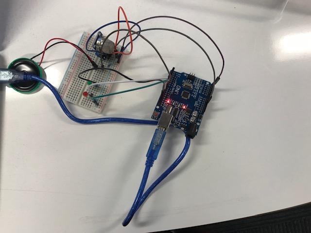
Circuit
The circuit in real life and what it is supposed to look like
Circuit
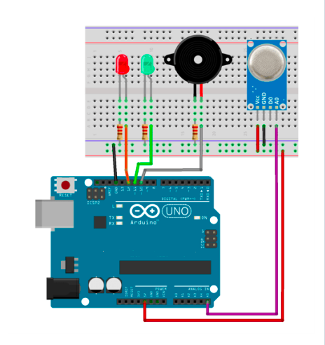
Fritzing Model
The MQ-5 sensor Pin-> Wiring to Arduino Uno A0-> Analog pins D0-> none GND-> GND VCC-> 5V other components Pin-> Wiring to Arduino Uno D13-> +ve of buzzer GND-> -ve of buzzer D12-> anode of red light D11-> anode of green light GND-> cathode of red light GND-> cathode of red light
Fritzing Model
Circuit
The circuit in real life and what it is supposed to look like
Circuit
Documentation
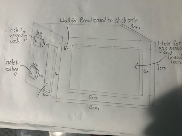
Casing
It is a casing for the gas sensor
Casing
Casing
It is a casing for the gas sensor
Casing
Comments
Only logged in users can leave comments