Devices & Components
nRF24 Module (Generic)
Analog joystick (Generic)
LCD Screen 16 x 2
Project description
Code
Basic Joystick Code
arduino
Learn how to read the signals coming from the on board analog joysticks.
1/*  Joystick_Basic Version 1.01
2 *  Author: Schindler Electronics
3  *  Data: 5/23/2019
4 *
5 *  This code reads the value of each joystick
6  *  axis using the Analog Read function.
7 *
8 *  Each value for the joystick  range should from 0-1023.
9 *  The push-buttons should read 0 when pushed and  1 when not pushed.
10 *
11 */
12
13void setup() {
14Serial.begin(115200);
15pinMode(5,  OUTPUT);    //Set the pins connected to the joystick button to an output
16pinMode(4,  OUTPUT);
17digitalWrite(5, HIGH); //Set the pins to HIGH (5V). When the button  is pressed it will pull the pin to ground (0V)
18digitalWrite(4, HIGH);
19}
20
21void  loop() {
22 Serial.print("Joystick L: ");
23 Serial.print(analogRead(A2)); //Read  the Joystick value
24 Serial.print("\	");
25 Serial.print(analogRead(A3));  //Read the Joystick value
26 Serial.print("\	");
27 Serial.print(digitalRead(4));  //Read the Button value
28 Serial.print("\	");
29
30 Serial.print("Joystick  R: "); //Read the Joystick value
31 Serial.print(analogRead(A0));
32 Serial.print("\	");
33  Serial.print(analogRead(A1)); //Read the Joystick value
34 Serial.print("\	");
35  Serial.print(digitalRead(5)); //Read the Button value
36 Serial.print("\	");
37
38 Serial.println();
39 delay(10);
40}
41
Simple Receive
arduino
This is the code to receive wireless communication from the Arduino and the NRF24L01+ module.
1/*  Simple Recieve Version 1.02
2 *  Author: Schindler Electronics
3  *  Data: 6/1/2019
4 *
5 *  This code demonstrates how to use the NRF module  to
6 *  receive simple data from another NRF module.
7 *
8 *  Note: This  code requires another Arduino transmitting data
9 *  from another NRF module using  the Simple_Transmit Sketch
10 *
11 *  Note: This code requires the use of the  RF24 Library.
12 *  You can easily download this library in the Arduino Library  Manager.
13 */
14
15#include <SPI.h>   //Comes with Arduino IDE
16#include "RF24.h"  //Download and Install (See above)
17
18#define  CE_PIN  7 //The pins to be  used for CE and CSN
19#define  CSN_PIN 8
20
21RF24 radio(CE_PIN, CSN_PIN);
22
23byte  addresses[][6] = {"1Node", "2Node"}; //These will be the names of the "Pipes"
24
25struct  dataStruct {       //this is the NRF data. Max of 32 bytes
26  int Xposition;          //int     = 2 bytes
27  int Yposition;          //double  = 4 bytes
28  bool switchOn;          //boolean = 1 byte
29
30  int X2position;
31  int Y2position;
32  bool switch2On;
33} myData;                //This  can be accessed in the form:  myData.Xposition  etc.
34
35void setup() {
36  Serial.begin(115200);
37  radio.begin();                   //Initialize the nRF24L01  Radio
38  radio.setChannel(108);           //Above most WiFi frequencies (2.4Ghz  + 0.108Ghz = 2.508Ghz)
39  radio.setDataRate(RF24_250KBPS); //Fast enough.. Better  range
40
41  radio.setPALevel(RF24_PA_MIN);   //This allows it to be used with  only USB power. Use of RF24_PA_MAX requires battery connection
42
43  radio.openWritingPipe(addresses[1]);    //Open a writing "Pipe" to send data out
44  radio.openReadingPipe(1, addresses[0]);  //Open a reading "Pipe" to receive data
45
46  radio.startListening();                 //Start  listening for incoming data
47}
48
49
50void loop() {
51
52  if (radio.available())  {
53    radio.read( &myData, sizeof(myData) );                //If the NRF  receives data on a Pipe read the data
54    Serial.print(myData.Xposition);  Serial.print("\	");  //Print the data received
55    Serial.print(myData.Yposition);  Serial.print("\	");
56    Serial.print(myData.switchOn);   Serial.print("\	");
57    Serial.print(myData.X2position);  Serial.print("\	");
58    Serial.print(myData.Y2position); Serial.print("\	");
59    Serial.print(myData.switch2On);  Serial.print("\	");
60    Serial.println();
61  }
62
63}
64
Simple Transmit Code
arduino
This is the code to transmit Wireless Information with the Arduino and the NRF24L01+ module. This code uses the RF24 Library.
1/*  Simple Transmit Version 1.02
2 *  Author: Schindler Electronics
3  *  Data: 6/1/2019
4 *
5 *  This code demonstrates how to use the NRF module  to
6 *  transmit simple data to another NRF module.
7 *
8 *  Note: This  code requires another Arduino receiving data
9 *  from another NRF module using  the Simple_Recieve Sketch
10 *
11 *  Note: This code requires the use of the  RF24 Library.
12 *  You can easily download this library in the Arduino Library  Manager.
13 *
14 *  Changes: The code now transmits the values of the joysticks  rather
15 *  than fixed values.
16 */
17
18#include <SPI.h>   //Comes with Arduino  IDE
19#include "RF24.h"  //Download and Install (See above)
20
21#define  CE_PIN  7 //The pins to be used for CE and CSN
22#define  CSN_PIN 8
23
24RF24 radio(CE_PIN,  CSN_PIN);
25
26byte addresses[][6] = {"1Node", "2Node"}; //These will be the  names of the "Pipes"
27
28struct dataStruct {       //this is the NRF data.  Max of 32 bytes
29  int Xposition;          //int     = 2 bytes
30  int Yposition;          //double  = 4 bytes
31  bool switchOn;          //boolean = 1 byte
32
33  int X2position;
34  int Y2position;
35  bool switch2On;
36}  myData;                //This can be accessed in the form:  myData.Xposition  etc.
37
38
39void  setup() {
40  Serial.begin(115200);
41  pinMode(5, OUTPUT);             //Set  up the Joysticks
42  pinMode(4, OUTPUT);
43  digitalWrite(5, HIGH);
44  digitalWrite(4,  HIGH);
45
46  radio.begin();                   //Initialize the nRF24L01 Radio
47  radio.setChannel(108);           //Above most WiFi frequencies
48  radio.setDataRate(RF24_250KBPS);  //Fast enough.. Better range
49
50  radio.setPALevel(RF24_PA_MIN);   //This allows  it to be used with only USB power. Use of RF24_PA_MAX requires battery connection
51
52  radio.openWritingPipe(addresses[0]);     //Open a writing "Pipe" to send data  out
53  radio.openReadingPipe(1, addresses[1]);  //Open a reading "Pipe" to receive  data
54
55  radio.stopListening();                   //Stop Listening so we can  start transmitting data
56  Serial.println("Set Up Complete");
57}
58
59
60void  loop() {
61    //This is the values that will be transmitted in the myData Struct
62    myData.Xposition = analogRead(A0);
63    myData.Yposition = analogRead(A1);
64    myData.switchOn  = digitalRead(5);
65
66    myData.X2position = analogRead(A2);
67    myData.Y2position = analogRead(A3);
68    myData.switch2On  = digitalRead(4);
69
70    radio.write(&myData, sizeof(myData), 1); //Transmit Data using the write command
71    Serial.println("Sent");
72    delay(10);
73}
74
Basic Joystick Code
arduino
Learn how to read the signals coming from the on board analog joysticks.
1/*  Joystick_Basic Version 1.01
2 *  Author: Schindler Electronics
3   *  Data: 5/23/2019
4 *
5 *  This code reads the value of each joystick
6   *  axis using the Analog Read function.
7 *
8 *  Each value for the joystick   range should from 0-1023.
9 *  The push-buttons should read 0 when pushed and   1 when not pushed.
10 *
11 */
12
13void setup() {
14Serial.begin(115200);
15pinMode(5,   OUTPUT);    //Set the pins connected to the joystick button to an output
16pinMode(4,   OUTPUT);
17digitalWrite(5, HIGH); //Set the pins to HIGH (5V). When the button   is pressed it will pull the pin to ground (0V)
18digitalWrite(4, HIGH);
19}
20
21void   loop() {
22 Serial.print("Joystick L: ");
23 Serial.print(analogRead(A2)); //Read   the Joystick value
24 Serial.print("\	");
25 Serial.print(analogRead(A3));   //Read the Joystick value
26 Serial.print("\	");
27 Serial.print(digitalRead(4));   //Read the Button value
28 Serial.print("\	");
29
30 Serial.print("Joystick   R: "); //Read the Joystick value
31 Serial.print(analogRead(A0));
32 Serial.print("\	");
33   Serial.print(analogRead(A1)); //Read the Joystick value
34 Serial.print("\	");
35   Serial.print(digitalRead(5)); //Read the Button value
36 Serial.print("\	");
37
38 Serial.println();
39 delay(10);
40}
41
Voltage Sensor Code
arduino
Learn how to read battery voltage with an Arduino!
1/*  Voltage Version 1.01
2 *  Author: Schindler Electronics
3 *  Data:  5/23/2019
4 *
5 *  This code demostrates how to read the voltage
6 *  applied  to the Battery pins of the Pilot RC
7 *
8 *  Note: This will display around  4.5 Volts when no battery is
9 *  applied to the pins. This is because the pins  are reading the
10 *  voltage coming out of the 5V voltage regulator.
11 */
12
13float  vPow = 5.0;   //constant for calculations (5V devices)
14float r1 = 49900;   //Value  of Resistor 1
15float r2 = 10000;   //Value of Resistor 2
16float v, v2, vAvg,  rcV, drV;
17int vNum;
18
19void setup() {
20  Serial.begin(115200);
21}
22
23
24void  loop() {
25   v = (analogRead(A4) * vPow) / 1024.0; //Value of the voltage coming  out of the voltage divider
26   v2 = v / (r2 / (r1 + r2));            //Actual  voltage applied to the voltage divider (Battery Voltage)
27   vAvg += v2;                           //We  want to average 100 readings of the battery voltage to achieve an accurate result
28   vNum++;
29
30  if (vNum == 100) {                     //Print the Voltage being  read by the Pilot RC and reset the counters
31    rcV = vAvg/100;
32    Serial.print("Voltage:  ");
33    Serial.println(rcV);
34    vNum=0;
35    vAvg=0;
36  }
37
38  delay(10);
39}
40
Simple Transmit Code
arduino
This is the code to transmit Wireless Information with the Arduino and the NRF24L01+ module. This code uses the RF24 Library.
1/*  Simple Transmit Version 1.02
2 *  Author: Schindler Electronics
3
4  *  Data: 6/1/2019
5 *
6 *  This code demonstrates how to use the NRF module
7  to
8 *  transmit simple data to another NRF module.
9 *
10 *  Note: This
11  code requires another Arduino receiving data
12 *  from another NRF module using
13  the Simple_Recieve Sketch
14 *
15 *  Note: This code requires the use of the
16  RF24 Library.
17 *  You can easily download this library in the Arduino Library
18  Manager.
19 *
20 *  Changes: The code now transmits the values of the joysticks
21  rather
22 *  than fixed values.
23 */
24
25#include <SPI.h>   //Comes with Arduino
26  IDE
27#include "RF24.h"  //Download and Install (See above)
28
29#define  CE_PIN
30  7 //The pins to be used for CE and CSN
31#define  CSN_PIN 8
32
33RF24 radio(CE_PIN,
34  CSN_PIN);
35
36byte addresses[][6] = {"1Node", "2Node"}; //These will be the
37  names of the "Pipes"
38
39struct dataStruct {       //this is the NRF data.
40  Max of 32 bytes
41  int Xposition;          //int     = 2 bytes
42  int Yposition;
43          //double  = 4 bytes
44  bool switchOn;          //boolean = 1 byte
45
46
47  int X2position;
48  int Y2position;
49  bool switch2On;
50}
51  myData;                //This can be accessed in the form:  myData.Xposition  etc.
52
53
54void
55  setup() {
56  Serial.begin(115200);
57  pinMode(5, OUTPUT);             //Set
58  up the Joysticks
59  pinMode(4, OUTPUT);
60  digitalWrite(5, HIGH);
61  digitalWrite(4,
62  HIGH);
63
64  radio.begin();                   //Initialize the nRF24L01 Radio
65
66  radio.setChannel(108);           //Above most WiFi frequencies
67  radio.setDataRate(RF24_250KBPS);
68  //Fast enough.. Better range
69
70  radio.setPALevel(RF24_PA_MIN);   //This allows
71  it to be used with only USB power. Use of RF24_PA_MAX requires battery connection
72
73
74  radio.openWritingPipe(addresses[0]);     //Open a writing "Pipe" to send data
75  out
76  radio.openReadingPipe(1, addresses[1]);  //Open a reading "Pipe" to receive
77  data
78
79  radio.stopListening();                   //Stop Listening so we can
80  start transmitting data
81  Serial.println("Set Up Complete");
82}
83
84
85void
86  loop() {
87    //This is the values that will be transmitted in the myData Struct
88
89    myData.Xposition = analogRead(A0);
90    myData.Yposition = analogRead(A1);
91
92    myData.switchOn  = digitalRead(5);
93
94    myData.X2position = analogRead(A2);
95
96    myData.Y2position = analogRead(A3);
97    myData.switch2On  = digitalRead(4);
98
99
100    radio.write(&myData, sizeof(myData), 1); //Transmit Data using the write command
101
102    Serial.println("Sent");
103    delay(10);
104}
105
Voltage Sensor Code
arduino
Learn how to read battery voltage with an Arduino!
1/*  Voltage Version 1.01
2 *  Author: Schindler Electronics
3 *  Data:
4  5/23/2019
5 *
6 *  This code demostrates how to read the voltage
7 *  applied
8  to the Battery pins of the Pilot RC
9 *
10 *  Note: This will display around
11  4.5 Volts when no battery is
12 *  applied to the pins. This is because the pins
13  are reading the
14 *  voltage coming out of the 5V voltage regulator.
15 */
16
17float
18  vPow = 5.0;   //constant for calculations (5V devices)
19float r1 = 49900;   //Value
20  of Resistor 1
21float r2 = 10000;   //Value of Resistor 2
22float v, v2, vAvg,
23  rcV, drV;
24int vNum;
25
26void setup() {
27  Serial.begin(115200);
28}
29
30
31void
32  loop() {
33   v = (analogRead(A4) * vPow) / 1024.0; //Value of the voltage coming
34  out of the voltage divider
35   v2 = v / (r2 / (r1 + r2));            //Actual
36  voltage applied to the voltage divider (Battery Voltage)
37   vAvg += v2;                           //We
38  want to average 100 readings of the battery voltage to achieve an accurate result
39
40   vNum++;
41
42  if (vNum == 100) {                     //Print the Voltage being
43  read by the Pilot RC and reset the counters
44    rcV = vAvg/100;
45    Serial.print("Voltage:
46  ");
47    Serial.println(rcV);
48    vNum=0;
49    vAvg=0;
50  }
51
52
53  delay(10);
54}
55
Downloadable files
schematic_9aA1vmIpMI.jpg
schematic_9aA1vmIpMI.jpg
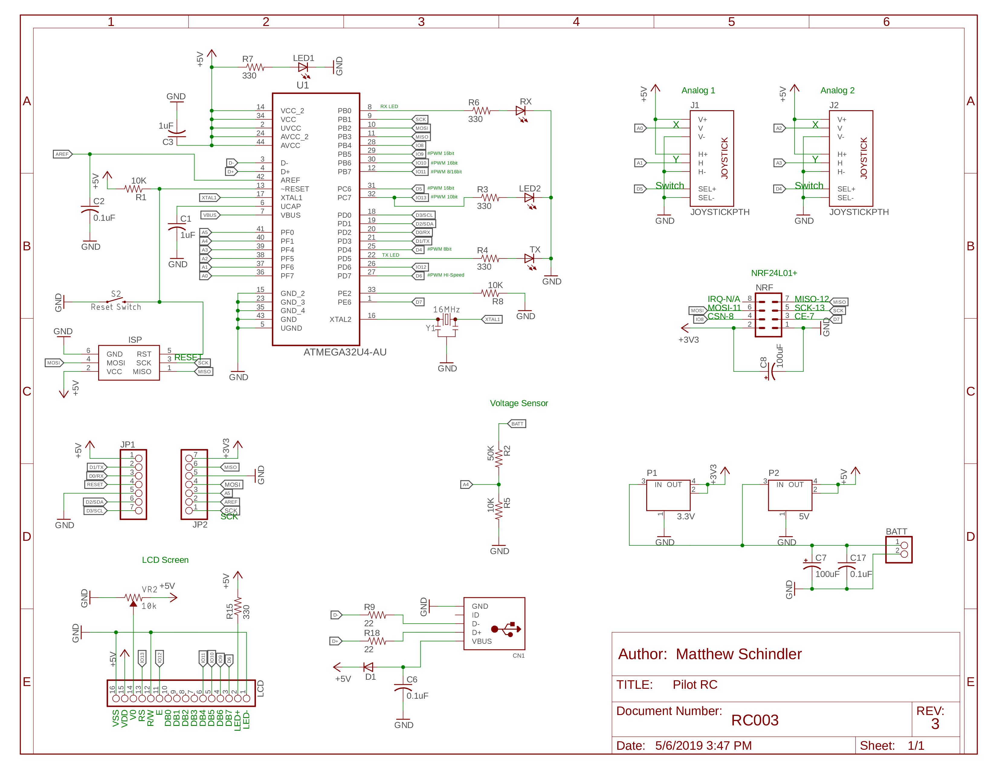
schematic_9aA1vmIpMI.jpg
schematic_9aA1vmIpMI.jpg
Documentation
3D Printed Case
The 3D printable case for the Pilot RC!
3D Printed Case
3D Printed Case
The 3D printable case for the Pilot RC!
3D Printed Case
Comments
Only logged in users can leave comments