DIY STM32 Alarm Clock with 7-Segment Display (Using Arduino IDE)
With its simple design, low cost, and easy setup, this STM32 alarm clock is a perfect DIY project for beginners and electronics enthusiasts alike.
Devices & Components
1
bluepill, stm32f103
4
Push Button
4
Metalfilm resistor 10k tolerance 0,1%
1
Grove - Buzzer - Piezo
1
DS3231 Real Time Clock Module
1
TM1637 Display
Hardware & Tools
1
Soldering kit
Software & Tools
Arduino IDE
Project description
Code
Code
cpp
...
Documentation
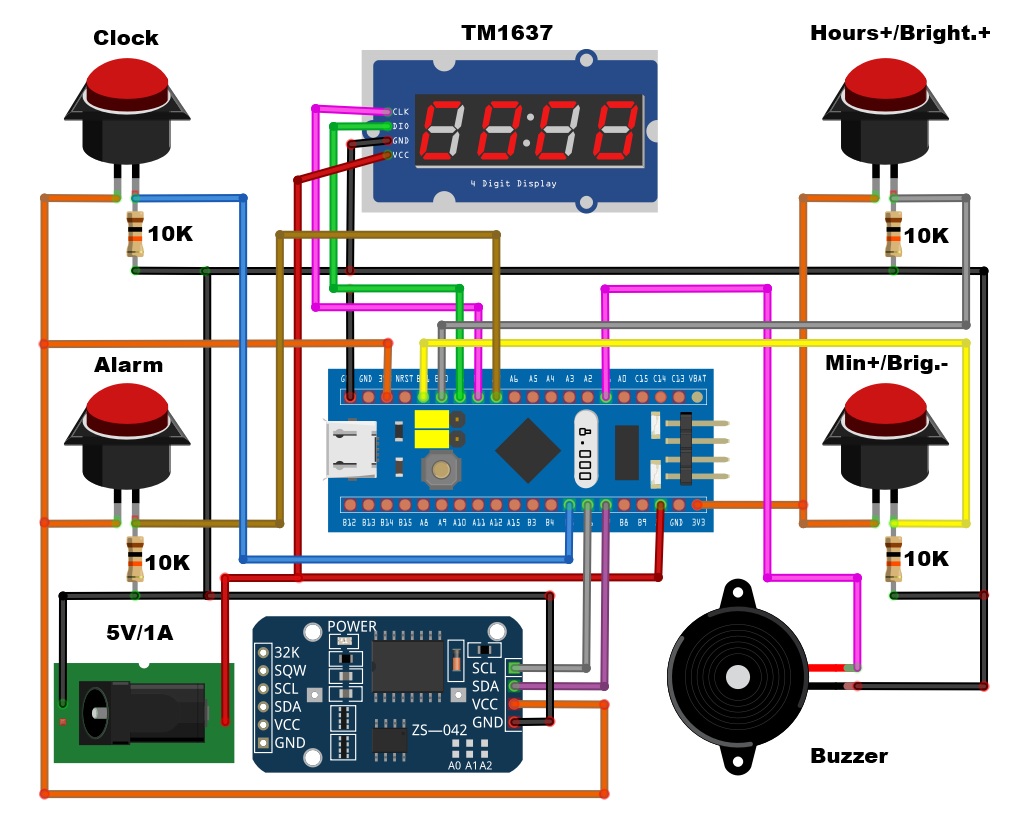
Schematic
...
SchematicJPG.jpg
Comments
Only logged in users can leave comments