ATtiny85 - Bi-direction Traffic Stop Light
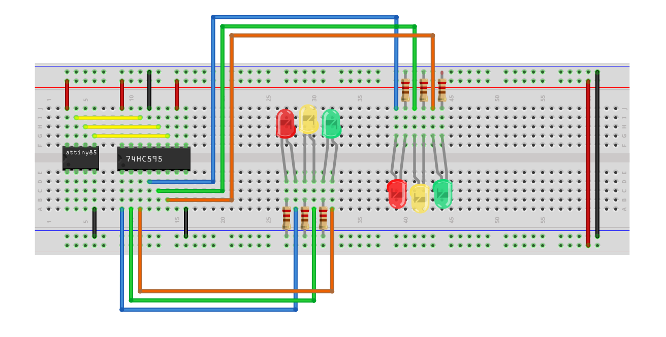
This is a simple Traffic Stop Light program written for an ATtiny85 & 74HC595 shift register.
Devices & Components
1
Tiny AVR Programmer
2
5 mm LED: Yellow
2
5 mm LED: Red
6
Resistor 220 ohm
1
Jumper wires (generic)
1
Solderless Breadboard Full Size
2
5 mm LED: Green
1
ATtiny85
1
Shift Register- Serial to Parallel
Software & Tools
1
Arduino IDE
Project description
Code
ATtiny85_AdvancedTrafficStopLight.ino
arduino
The full code.
1/* ATtiny85 - Advanced Traffic Stop Light - Version 0.1.0 - 2020-02-18
2  * Copyright (c) 2020 Matt Rude <matt@mattrude.com>
3 *
4 * *********************************************************************************
5  *
6 * This is a Advanced Traffic Stop Light program written for an ATtiny85 using
7  * Arduino IDE.
8 *
9 * The program was written for an ATtiny85 using Arduino  IDE and the 'ATTinyCore'
10 * board found at: https://github.com/SpenceKonde/ATTinyCore
11  *
12 * For more on the ATtiny85, see: https://www.microchip.com/wwwproducts/en/ATtiny85
13  *
14 * The ATtiny85 was programed with the external programer, and is running  is at a
15 * clock speed of 1MHz (internal).
16 *
17 * The circuit is powered  by an external DC buck converter running at 5v.
18 *
19 * *********************************************************************************
20  *
21 * Required Hardware:
22 *
23 * - 1x 1330 ATtiny85-20pu
24 * - 1x 74HC959  Shift Register
25 * - 2x Red LED
26 * - 2x Yellow LED
27 * - 2x Green LED
28  * - 6x 220 ohm Resistors
29 * - 1x Large Breadboard
30 * - 20x Jumper Wires
31  *
32 * Simplified ATtiny85 Pinout:
33 *   (Note: the dot next to the Reset pin  represents the dot on the chip.)
34 *              ______
35  *     Reset - |.     | - +5v
36 *    A3 - 3 - |      | - 2 - A1
37 *    A2 - 4  - |      | - 1 - PWM
38 *       GND - |______| - 0 - PWM
39 *
40 * 74HC959 Shift  Register Pinout:
41 *   (Note: the dot next to the Q1 pin represents the dot on  the chip.)
42 *              ______
43 *        Q1 - |.     | - +5v
44  *        Q2 - |      | - Q0
45 *        Q3 - |      | - DS
46 *        Q4 - |      | - OE
47 *        Q5 - |      | - STCP
48 *        Q6 - |      | - SHCP
49  *        Q7 - |      | - MR
50 *       GND - |______| - Q7S
51 *
52 * *********************************************************************************
53  *
54 * Changelog:
55 *
56 * 2020-02-18 - 0.1.0 - Initial Release.
57 *
58  * *********************************************************************************
59  *
60 * MIT License
61 *
62 * Copyright (c) 2020 Matt Rude <matt@mattrude.com>
63  *
64 * Permission is hereby granted, free of charge, to any person obtaining a  copy
65 * of this software and associated documentation files (the "Software"),  to deal
66 * in the Software without restriction, including without limitation  the rights
67 * to use, copy, modify, merge, publish, distribute, sublicense, and/or  sell
68 * copies of the Software, and to permit persons to whom the Software is
69  * furnished to do so, subject to the following conditions:
70 *
71 * The above  copyright notice and this permission notice shall be included in all
72 * copies  or substantial portions of the Software.
73 *
74 * THE SOFTWARE IS PROVIDED "AS  IS", WITHOUT WARRANTY OF ANY KIND, EXPRESS OR
75 * IMPLIED, INCLUDING BUT NOT  LIMITED TO THE WARRANTIES OF MERCHANTABILITY,
76 * FITNESS FOR A PARTICULAR PURPOSE  AND NONINFRINGEMENT. IN NO EVENT SHALL THE
77 * AUTHORS OR COPYRIGHT HOLDERS BE  LIABLE FOR ANY CLAIM, DAMAGES OR OTHER
78 * LIABILITY, WHETHER IN AN ACTION OF  CONTRACT, TORT OR OTHERWISE, ARISING FROM,
79 * OUT OF OR IN CONNECTION WITH THE  SOFTWARE OR THE USE OR OTHER DEALINGS IN THE
80 * SOFTWARE.
81 *
82 * *********************************************************************************
83  */
84
85// This is the amount of time, in seconds, to wait between light changes.
86int  changeDelay = 30;
87
88// Declare the shift register pins
89int clockPin    =  0;      // Connected to SHCP (pin 11) on the 74HC595.
90int latchPin    = 1;      //  Connected to STCP (pin 12) on the 74HC595.
91int dataPin     = 2;      // Connected  to DS (pin 14) on the 74HC595.
92
93void setup() {
94  // Set the three shift  register pins to output.
95  pinMode(clockPin, OUTPUT);
96  pinMode(latchPin,  OUTPUT);
97  pinMode(dataPin, OUTPUT);
98
99  // Start with the clockPin set  to a LOW state
100  digitalWrite(clockPin, LOW);
101}
102
103void loop() {
104  //  Set the Both directions to Red
105  digitalWrite(latchPin, LOW);
106  shiftOut(dataPin,  clockPin, MSBFIRST, 0b00100010);
107  digitalWrite(latchPin, HIGH);
108  delay((changeDelay*100)/8);
109
110  // Set the first directions to Green and the second to Red
111  digitalWrite(latchPin,  LOW);
112  shiftOut(dataPin, clockPin, MSBFIRST, 0b10000010);
113  digitalWrite(latchPin,  HIGH);
114  delay(changeDelay*100);
115
116  // Set the first directions to Yellow  and keep the second direction Red
117  digitalWrite(latchPin, LOW);
118  shiftOut(dataPin,  clockPin, MSBFIRST, 0b01000010);
119  digitalWrite(latchPin, HIGH);
120  delay((changeDelay*100)/4);
121
122  // Set the Both directions to Red
123  digitalWrite(latchPin, LOW);
124  shiftOut(dataPin,  clockPin, MSBFIRST, 0b00100010);
125  digitalWrite(latchPin, HIGH);
126  delay((changeDelay*100)/8);
127
128  // Set the first directions to Red and the second to Green
129  digitalWrite(latchPin,  LOW);
130  shiftOut(dataPin, clockPin, MSBFIRST, 0b00101000);
131  digitalWrite(latchPin,  HIGH);
132  delay(changeDelay*100);
133
134  // Set the first directions to Yellow  and keep the second direction Red
135  digitalWrite(latchPin, LOW);
136  shiftOut(dataPin,  clockPin, MSBFIRST, 0b00100100);
137  digitalWrite(latchPin, HIGH);
138  delay((changeDelay*100)/4);
139}
ATtiny85_AdvancedTrafficStopLight.ino
arduino
The full code.
1/* ATtiny85 - Advanced Traffic Stop Light - Version 0.1.0 - 2020-02-18
2
3  * Copyright (c) 2020 Matt Rude <matt@mattrude.com>
4 *
5 * *********************************************************************************
6
7  *
8 * This is a Advanced Traffic Stop Light program written for an ATtiny85 using
9
10  * Arduino IDE.
11 *
12 * The program was written for an ATtiny85 using Arduino
13  IDE and the 'ATTinyCore'
14 * board found at: https://github.com/SpenceKonde/ATTinyCore
15
16  *
17 * For more on the ATtiny85, see: https://www.microchip.com/wwwproducts/en/ATtiny85
18
19  *
20 * The ATtiny85 was programed with the external programer, and is running
21  is at a
22 * clock speed of 1MHz (internal).
23 *
24 * The circuit is powered
25  by an external DC buck converter running at 5v.
26 *
27 * *********************************************************************************
28
29  *
30 * Required Hardware:
31 *
32 * - 1x 1330 ATtiny85-20pu
33 * - 1x 74HC959
34  Shift Register
35 * - 2x Red LED
36 * - 2x Yellow LED
37 * - 2x Green LED
38
39  * - 6x 220 ohm Resistors
40 * - 1x Large Breadboard
41 * - 20x Jumper Wires
42
43  *
44 * Simplified ATtiny85 Pinout:
45 *   (Note: the dot next to the Reset pin
46  represents the dot on the chip.)
47 *              ______
48
49  *     Reset - |.     | - +5v
50 *    A3 - 3 - |      | - 2 - A1
51 *    A2 - 4
52  - |      | - 1 - PWM
53 *       GND - |______| - 0 - PWM
54 *
55 * 74HC959 Shift
56  Register Pinout:
57 *   (Note: the dot next to the Q1 pin represents the dot on
58  the chip.)
59 *              ______
60 *        Q1 - |.     | - +5v
61
62  *        Q2 - |      | - Q0
63 *        Q3 - |      | - DS
64 *        Q4 - |
65      | - OE
66 *        Q5 - |      | - STCP
67 *        Q6 - |      | - SHCP
68
69  *        Q7 - |      | - MR
70 *       GND - |______| - Q7S
71 *
72 * *********************************************************************************
73
74  *
75 * Changelog:
76 *
77 * 2020-02-18 - 0.1.0 - Initial Release.
78 *
79
80  * *********************************************************************************
81
82  *
83 * MIT License
84 *
85 * Copyright (c) 2020 Matt Rude <matt@mattrude.com>
86
87  *
88 * Permission is hereby granted, free of charge, to any person obtaining a
89  copy
90 * of this software and associated documentation files (the "Software"),
91  to deal
92 * in the Software without restriction, including without limitation
93  the rights
94 * to use, copy, modify, merge, publish, distribute, sublicense, and/or
95  sell
96 * copies of the Software, and to permit persons to whom the Software is
97
98  * furnished to do so, subject to the following conditions:
99 *
100 * The above
101  copyright notice and this permission notice shall be included in all
102 * copies
103  or substantial portions of the Software.
104 *
105 * THE SOFTWARE IS PROVIDED "AS
106  IS", WITHOUT WARRANTY OF ANY KIND, EXPRESS OR
107 * IMPLIED, INCLUDING BUT NOT
108  LIMITED TO THE WARRANTIES OF MERCHANTABILITY,
109 * FITNESS FOR A PARTICULAR PURPOSE
110  AND NONINFRINGEMENT. IN NO EVENT SHALL THE
111 * AUTHORS OR COPYRIGHT HOLDERS BE
112  LIABLE FOR ANY CLAIM, DAMAGES OR OTHER
113 * LIABILITY, WHETHER IN AN ACTION OF
114  CONTRACT, TORT OR OTHERWISE, ARISING FROM,
115 * OUT OF OR IN CONNECTION WITH THE
116  SOFTWARE OR THE USE OR OTHER DEALINGS IN THE
117 * SOFTWARE.
118 *
119 * *********************************************************************************
120
121  */
122
123// This is the amount of time, in seconds, to wait between light changes.
124int
125  changeDelay = 30;
126
127// Declare the shift register pins
128int clockPin    =
129  0;      // Connected to SHCP (pin 11) on the 74HC595.
130int latchPin    = 1;      //
131  Connected to STCP (pin 12) on the 74HC595.
132int dataPin     = 2;      // Connected
133  to DS (pin 14) on the 74HC595.
134
135void setup() {
136  // Set the three shift
137  register pins to output.
138  pinMode(clockPin, OUTPUT);
139  pinMode(latchPin,
140  OUTPUT);
141  pinMode(dataPin, OUTPUT);
142
143  // Start with the clockPin set
144  to a LOW state
145  digitalWrite(clockPin, LOW);
146}
147
148void loop() {
149  //
150  Set the Both directions to Red
151  digitalWrite(latchPin, LOW);
152  shiftOut(dataPin,
153  clockPin, MSBFIRST, 0b00100010);
154  digitalWrite(latchPin, HIGH);
155  delay((changeDelay*100)/8);
156
157
158  // Set the first directions to Green and the second to Red
159  digitalWrite(latchPin,
160  LOW);
161  shiftOut(dataPin, clockPin, MSBFIRST, 0b10000010);
162  digitalWrite(latchPin,
163  HIGH);
164  delay(changeDelay*100);
165
166  // Set the first directions to Yellow
167  and keep the second direction Red
168  digitalWrite(latchPin, LOW);
169  shiftOut(dataPin,
170  clockPin, MSBFIRST, 0b01000010);
171  digitalWrite(latchPin, HIGH);
172  delay((changeDelay*100)/4);
173
174
175  // Set the Both directions to Red
176  digitalWrite(latchPin, LOW);
177  shiftOut(dataPin,
178  clockPin, MSBFIRST, 0b00100010);
179  digitalWrite(latchPin, HIGH);
180  delay((changeDelay*100)/8);
181
182
183  // Set the first directions to Red and the second to Green
184  digitalWrite(latchPin,
185  LOW);
186  shiftOut(dataPin, clockPin, MSBFIRST, 0b00101000);
187  digitalWrite(latchPin,
188  HIGH);
189  delay(changeDelay*100);
190
191  // Set the first directions to Yellow
192  and keep the second direction Red
193  digitalWrite(latchPin, LOW);
194  shiftOut(dataPin,
195  clockPin, MSBFIRST, 0b00100100);
196  digitalWrite(latchPin, HIGH);
197  delay((changeDelay*100)/4);
198}
Downloadable files
The full build
The full build
Comments
Only logged in users can leave comments