Devices & Components
zmpt 101b
MapleTree Mini - STM32duino STM32F103RB Compatible with Leaf Maple
SCT-013
NodeMCU ESP8266 Breakout Board
Software & Tools
Blynk
Project description
Code
Code that is compiled into the NodeMCU
arduino
Code that is compiled into the NodeMCU, Basically it makes a serial communication with the STM32 and sends all that info to Blynk app.
1#define BLYNK_PRINT Serial
2#include <ESP8266WiFi.h>
3#include <BlynkSimpleEsp8266.h>
4#include  <ArduinoJson.h>
5#include <SoftwareSerial.h>
6SoftwareSerial s(3,1);
7
8//TX  RX como serial.
9//LEMBRAR DE LIGAR OS TERRAS JUNTOS.
10
11// You should get  Auth Token in the Blynk App.
12// Go to the Project Settings (nut icon).
13char  auth[] = "EBzOKyeWePRCay5fP8tY-eMnQVQmY0x5";
14
15// Your WiFi credentials.
16//  Set password to "" for open networks.
17char ssid[] = "motorolaone";
18char  pass[] = "batata12";
19WidgetLCD lcd(V10);
20int value;
21String PotFase1;
22String  PotFase2;
23String PotFase3;
24int Pot1;
25int Pot2;
26int Pot3;
27int i1;
28int  i2;
29int i3;
30int v1;
31int v2;
32int v3;
33int FP1;
34int FP2;
35int FP3;
36int  Energia;
37float Preco;
38int PotAux;
39char serialRead;
40BlynkTimer timer;
41
42//  This function sends Arduino's up time every second to Virtual Pin (5).
43// In  the app, Widget's reading frequency should be set to PUSH. This means
44// that  you define how often to send data to Blynk App.
45
46
47void myTimerEvent()
48{
49
50
51  Blynk.virtualWrite(V1,Pot1);
52  delay(50);
53  Blynk.virtualWrite(V2,Pot2);
54  delay(50);
55  Blynk.virtualWrite(V3,Pot3);
56  delay(50);
57  Blynk.virtualWrite(V4,v1);
58  delay(50);
59  Blynk.virtualWrite(V5,i1);
60  delay(50);
61  Blynk.virtualWrite(V6,v2);
62  delay(50);
63  Blynk.virtualWrite(V7,i2);
64  delay(50);
65  Blynk.virtualWrite(V8,v3);
66  delay(80);
67  Blynk.virtualWrite(V9,i3);
68  delay(50);
69  Blynk.virtualWrite(V10,FP1);
70  delay(50);
71  Blynk.virtualWrite(V11,FP2);
72  delay(50);
73  Blynk.virtualWrite(V12,FP3);
74  delay(50);
75
76
77
78
79
80
81  // You can send any value at  any time.
82  // Please don't send more that 10 values per second.
83}
84
85void  setup()
86{
87  // Debug console
88  Serial.begin(9600);
89  s.begin(9600);
90  while (!Serial) continue;
91  Blynk.begin(auth, ssid, pass);
92  timer.setInterval(2000L,  myTimerEvent);
93}
94
95void loop()
96{
97  s.write("s");
98  if (s.available()>0)
99  {
100   serialRead = s.read();
101   if (serialRead == 'A'){
102      s.write("s");
103     if (s.available()>0){
104     PotAux=s.read();
105     if(PotAux>=0){
106      Pot1=PotAux;}}
107      s.write("s");
108      if (s.available()>0){
109      PotAux=s.read();
110      if(PotAux>=0){
111      Pot1=100*PotAux+Pot1;}}
112   }
113   if (serialRead  == 'B'){
114      s.write("s");
115     if (s.available()>0){
116     PotAux=s.read();
117     if(PotAux>=0){
118      Pot2=PotAux;}}
119      s.write("s");
120      if  (s.available()>0){
121      PotAux=s.read();
122      if(PotAux>=0){
123      Pot2=100*PotAux+Pot2;}}
124   }
125
126   if (serialRead == 'C'){
127      s.write("s");
128      if (s.available()>0){
129      PotAux=s.read();
130     if(PotAux>=0){
131      Pot3=PotAux;}}
132      s.write("s");
133      if (s.available()>0){
134      PotAux=s.read();
135      if(PotAux>=0){
136      Pot3=100*PotAux+Pot3;}}
137   }
138
139   if (serialRead == 'D'){
140      s.write("s");
141      PotAux=s.read();
142     if(PotAux>=0){
143      i1=PotAux;}
144   }
145
146  if (serialRead == 'E'){
147      s.write("s");
148      PotAux=s.read();
149     if(PotAux>=0){
150      v1=PotAux;}
151   }
152
153   if (serialRead == 'F'){
154      s.write("s");
155      PotAux=s.read();
156     if(PotAux>=0){
157      i2=PotAux;}
158   }
159
160   if (serialRead == 'G'){
161      s.write("s");
162      PotAux=s.read();
163     if(PotAux>=0){
164      v2=PotAux;}
165   }
166
167
168   if (serialRead ==  'H'){
169      s.write("s");
170      PotAux=s.read();
171     if(PotAux>=0){
172      i3=PotAux;}
173   }
174
175   if (serialRead == 'I'){
176      s.write("s");
177      PotAux=s.read();
178     if(PotAux>=0){
179      v3=PotAux;}
180   }
181
182   if (serialRead == 'J'){
183      s.write("s");
184      PotAux=s.read();
185     if(PotAux>=0){
186      Energia=PotAux;}
187   }
188
189   if (serialRead ==  'K'){
190      s.write("s");
191      PotAux=s.read();
192     if(PotAux>=0){
193      FP1=PotAux;}
194   }
195
196   if (serialRead == 'L'){
197      s.write("s");
198      PotAux=s.read();
199     if(PotAux>=0){
200      FP2=PotAux;}
201   }
202
203   if (serialRead == 'M'){
204      s.write("s");
205      PotAux=s.read();
206     if(PotAux>=0){
207      FP3=PotAux;}
208   }
209
210  }
211
212
213
214  Blynk.run();
215  timer.run(); // Initiates BlynkTimer
216}
Code that is compiled into the NodeMCU
arduino
Code that is compiled into the NodeMCU, Basically it makes a serial communication with the STM32 and sends all that info to Blynk app.
1#define BLYNK_PRINT Serial
2#include <ESP8266WiFi.h>
3#include <BlynkSimpleEsp8266.h>
4#include
5  <ArduinoJson.h>
6#include <SoftwareSerial.h>
7SoftwareSerial s(3,1);
8
9//TX
10  RX como serial.
11//LEMBRAR DE LIGAR OS TERRAS JUNTOS.
12
13// You should get
14  Auth Token in the Blynk App.
15// Go to the Project Settings (nut icon).
16char
17  auth[] = "EBzOKyeWePRCay5fP8tY-eMnQVQmY0x5";
18
19// Your WiFi credentials.
20//
21  Set password to "" for open networks.
22char ssid[] = "motorolaone";
23char
24  pass[] = "batata12";
25WidgetLCD lcd(V10);
26int value;
27String PotFase1;
28String
29  PotFase2;
30String PotFase3;
31int Pot1;
32int Pot2;
33int Pot3;
34int i1;
35int
36  i2;
37int i3;
38int v1;
39int v2;
40int v3;
41int FP1;
42int FP2;
43int FP3;
44int
45  Energia;
46float Preco;
47int PotAux;
48char serialRead;
49BlynkTimer timer;
50
51//
52  This function sends Arduino's up time every second to Virtual Pin (5).
53// In
54  the app, Widget's reading frequency should be set to PUSH. This means
55// that
56  you define how often to send data to Blynk App.
57
58
59void myTimerEvent()
60{
61
62
63
64  Blynk.virtualWrite(V1,Pot1);
65  delay(50);
66  Blynk.virtualWrite(V2,Pot2);
67
68  delay(50);
69  Blynk.virtualWrite(V3,Pot3);
70  delay(50);
71  Blynk.virtualWrite(V4,v1);
72
73  delay(50);
74  Blynk.virtualWrite(V5,i1);
75  delay(50);
76  Blynk.virtualWrite(V6,v2);
77
78  delay(50);
79  Blynk.virtualWrite(V7,i2);
80  delay(50);
81  Blynk.virtualWrite(V8,v3);
82
83  delay(80);
84  Blynk.virtualWrite(V9,i3);
85  delay(50);
86  Blynk.virtualWrite(V10,FP1);
87
88  delay(50);
89  Blynk.virtualWrite(V11,FP2);
90  delay(50);
91  Blynk.virtualWrite(V12,FP3);
92
93  delay(50);
94
95
96
97
98
99
100  // You can send any value at
101  any time.
102  // Please don't send more that 10 values per second.
103}
104
105void
106  setup()
107{
108  // Debug console
109  Serial.begin(9600);
110  s.begin(9600);
111
112  while (!Serial) continue;
113  Blynk.begin(auth, ssid, pass);
114  timer.setInterval(2000L,
115  myTimerEvent);
116}
117
118void loop()
119{
120  s.write("s");
121  if (s.available()>0)
122
123  {
124   serialRead = s.read();
125   if (serialRead == 'A'){
126      s.write("s");
127
128     if (s.available()>0){
129     PotAux=s.read();
130     if(PotAux>=0){
131      Pot1=PotAux;}}
132
133      s.write("s");
134      if (s.available()>0){
135      PotAux=s.read();
136
137      if(PotAux>=0){
138      Pot1=100*PotAux+Pot1;}}
139   }
140   if (serialRead
141  == 'B'){
142      s.write("s");
143     if (s.available()>0){
144     PotAux=s.read();
145
146     if(PotAux>=0){
147      Pot2=PotAux;}}
148      s.write("s");
149      if
150  (s.available()>0){
151      PotAux=s.read();
152      if(PotAux>=0){
153      Pot2=100*PotAux+Pot2;}}
154
155   }
156
157   if (serialRead == 'C'){
158      s.write("s");
159      if (s.available()>0){
160
161      PotAux=s.read();
162     if(PotAux>=0){
163      Pot3=PotAux;}}
164      s.write("s");
165
166      if (s.available()>0){
167      PotAux=s.read();
168      if(PotAux>=0){
169
170      Pot3=100*PotAux+Pot3;}}
171   }
172
173   if (serialRead == 'D'){
174      s.write("s");
175
176      PotAux=s.read();
177     if(PotAux>=0){
178      i1=PotAux;}
179   }
180
181
182  if (serialRead == 'E'){
183      s.write("s");
184      PotAux=s.read();
185
186     if(PotAux>=0){
187      v1=PotAux;}
188   }
189
190   if (serialRead == 'F'){
191
192      s.write("s");
193      PotAux=s.read();
194     if(PotAux>=0){
195      i2=PotAux;}
196
197   }
198
199   if (serialRead == 'G'){
200      s.write("s");
201      PotAux=s.read();
202
203     if(PotAux>=0){
204      v2=PotAux;}
205   }
206
207
208   if (serialRead ==
209  'H'){
210      s.write("s");
211      PotAux=s.read();
212     if(PotAux>=0){
213
214      i3=PotAux;}
215   }
216
217   if (serialRead == 'I'){
218      s.write("s");
219
220      PotAux=s.read();
221     if(PotAux>=0){
222      v3=PotAux;}
223   }
224
225
226   if (serialRead == 'J'){
227      s.write("s");
228      PotAux=s.read();
229
230     if(PotAux>=0){
231      Energia=PotAux;}
232   }
233
234   if (serialRead ==
235  'K'){
236      s.write("s");
237      PotAux=s.read();
238     if(PotAux>=0){
239
240      FP1=PotAux;}
241   }
242
243   if (serialRead == 'L'){
244      s.write("s");
245
246      PotAux=s.read();
247     if(PotAux>=0){
248      FP2=PotAux;}
249   }
250
251
252   if (serialRead == 'M'){
253      s.write("s");
254      PotAux=s.read();
255
256     if(PotAux>=0){
257      FP3=PotAux;}
258   }
259
260  }
261
262
263
264
265  Blynk.run();
266  timer.run(); // Initiates BlynkTimer
267}
Code that is compiled into the STM32f103
arduino
Code that is compiled into the STM32f103. All functions used in metering are implemented in this code
1#include <LiquidCrystal.h>
2
3
4const int rs = PB11, en = PB10,  d4 = PA7, d5 = PA6, d6 = PC13, d7 = PC14; //mention the pin names to with LCD is  connected to
5LiquidCrystal lcd(rs, en, d4, d5, d6, d7); //Initialize the LCD
6float  Tensao;
7float Corrente;
8float Potencia;
9float Energia=0;
10float EnergiaAux;
11int  T_sample;
12int Fase;
13const int PinTensao1=PB0;
14const int PinCorrente1=PA0;
15const  int PinTensao2=PB1;
16const int PinCorrente2=PA1;
17const int PinTensao3=PA5;
18const  int PinCorrente3=PA4;
19const int PinbotaoMode=PA11;
20const int PinbotaoZerar=PA12;
21//EnergyMonitor  SCT1;
22//EnergyMonitor SCT2;
23//EnergyMonitor SCT3;
24int botaoMode=0;
25int  estado1;
26int estado2;
27int estadoAux;
28int ZeroTP1;
29int ZeroTP2;
30int  ZeroTP3;
31int ZeroTC1;
32int ZeroTC2;
33int ZeroTC3;
34int PotFase11;
35int  PotFase21;
36int PotFase31;
37int PotFase12;
38int PotFase22;
39int PotFase32;
40int  Potfin;
41int i1;
42int i2;
43int i3;
44int v1;
45int v2;
46int v3;
47int  FP1;
48int FP2;
49int FP3;
50float FPaux;
51unsigned long Tempo1;
52unsigned  long Tempo2;
53unsigned long Tempo3;
54
55void setup() {
56
57  Serial1.begin(9600);
58  lcd.begin(16, 2);//We are using a 16*2 LCD
59  analogReadResolution(12);
60  pinMode(PinTensao1, INPUT);
61  pinMode(PinCorrente1, INPUT);
62  pinMode(PinTensao2,  INPUT);
63  pinMode(PinCorrente2, INPUT);
64  pinMode(PinTensao3, INPUT);
65  pinMode(PinCorrente3, INPUT);
66  pinMode(PinbotaoMode, INPUT);
67  pinMode(PinbotaoZerar,  INPUT);
68  Fase=0;
69  T_sample=10;
70  estado1=LOW;
71  estado2=HIGH;
72  estadoAux=0;
73  lcd.setCursor(0, 0);
74  lcd.print("Aguarde a config");
75  lcd.setCursor(0, 1);
76  lcd.print("A Vazio");
77  delay(10000);
78
79
80  ZeroTP1=ZeroADC(PinTensao1);
81  ZeroTP2=ZeroADC(PinTensao2);
82  ZeroTP3=ZeroADC(PinTensao3);
83  ZeroTC1=ZeroADC(PinCorrente1)-5;
84  ZeroTC2=ZeroADC(PinCorrente2);
85  ZeroTC3=ZeroADC(PinCorrente3);
86  //ZeroTP1=100;
87  //ZeroTP2=0;
88  //ZeroTP3=0;
89  //ZeroTC1=100;
90  //ZeroTC2=100;
91  //ZeroTC3=100;
92  lcd.clear();
93  lcd.setCursor(0, 0);
94  delay(1500);
95  lcd.print("Configurado!");
96  delay(1500);
97
98}
99
100
101void loop()  {
102  Tempo1=micros();
103  if(Fase==0){
104
105    //Bloco para teste de  valor maximo digital, tempo para realização do analog read.
106    //lcd.setCursor(0,  0); //elemento 1x1
107    //Tempo1=micros();
108    //Tensao = analogRead(PinTensao1);
109    //Tempo2=micros();
110    //lcd.print(Tensao);
111    //lcd.setCursor(0, 1);
112    //Tempo3=Tempo2-Tempo1;
113    //lcd.print(Tempo2-Tempo1);
114
115    Potencia=LCDMode(botaoMode,Fase,PinCorrente1,PinTensao1,Energia,ZeroTP1,ZeroTC1);
116    PotFase11=(int)Potencia/100;
117    PotFase12=Potencia - 100*PotFase11;
118    i1=arredonda(RMS(52.5,PinCorrente1,1000,ZeroTC1));
119    v1=arredonda(RMS(403,PinTensao1,1000,ZeroTP1));
120    FPaux=FatordePotencia(PinTensao1,PinCorrente1,ZeroTP1,ZeroTC1,403,52.5);
121    FP1=(int)100*abs(FPaux);
122
123
124  }
125  if(Fase==1){
126    Potencia=LCDMode(botaoMode,Fase,PinCorrente2,PinTensao2,Energia,ZeroTP2,ZeroTC2);
127    PotFase21=(int)Potencia/100;
128    PotFase22=Potencia - 100*PotFase21;
129    i2=arredonda(RMS(52.5,PinCorrente2,1000,ZeroTC2));
130    v2=arredonda(RMS(403,PinTensao2,1000,ZeroTP2));
131    FPaux=(int) 100*FatordePotencia(PinTensao2,PinCorrente2,ZeroTP2,ZeroTC2,403,52.5);
132    FP2=(int)100*abs(FPaux);
133  }
134  if(Fase==2){
135    Potencia=LCDMode(botaoMode,Fase,PinCorrente3,PinTensao3,Energia,ZeroTP3,ZeroTC3);
136    PotFase31=(int)Potencia/100;
137    PotFase32=Potencia - 100*PotFase31;
138    i3=arredonda(RMS(52.5,PinCorrente3,1000,ZeroTC3));
139    v3=arredonda(RMS(403,PinTensao3,1000,ZeroTP3));
140    FPaux=(int) 100*FatordePotencia(PinTensao3,PinCorrente3,ZeroTP3,ZeroTC3,403,52.5);
141    FP3=(int)100*abs(FPaux);
142  }
143
144
145
146
147        if(Serial1.available()>0)      // comunicação serial com o ESP8266
148                                       //Cada  letra tem um feature sendo enviado
149            {
150
151             Serial1.write('A');
152             if(Serial1.available()>0)
153            {
154             Serial1.write(PotFase12);
155               if(Serial1.available()>0){
156               Serial1.write(PotFase11);
157               }
158             }
159
160             Serial1.write('B');
161             if(Serial1.available()>0)
162            {
163             Serial1.write(PotFase22);
164               if(Serial1.available()>0){
165               Serial1.write(PotFase21);
166               }
167             }
168
169
170             Serial1.write('C');
171             if(Serial1.available()>0)
172            {
173             Serial1.write(PotFase32);
174               if(Serial1.available()>0){
175               Serial1.write(PotFase31);
176               }
177             }
178
179             Serial1.write('D');
180             if(Serial1.available()>0)
181            {
182             Serial1.write(i1);}
183
184             Serial1.write('E');
185             if(Serial1.available()>0)
186            {
187             Serial1.write(v1);}
188
189
190             Serial1.write('F');
191             if(Serial1.available()>0)
192            {
193             Serial1.write(i2);}
194
195             Serial1.write('G');
196             if(Serial1.available()>0)
197            {
198             Serial1.write(v2);}
199
200
201             Serial1.write('H');
202             if(Serial1.available()>0)
203            {
204             Serial1.write(i3);}
205
206
207             Serial1.write('I');
208             if(Serial1.available()>0)
209            {
210             Serial1.write(v3);}
211
212             Serial1.write('J');
213             if(Serial1.available()>0)
214            {
215             Serial1.write(arredonda(Energia));}
216
217             Serial1.write('K');
218             if(Serial1.available()>0)
219            {
220             Serial1.write(FP1);}
221
222            Serial1.write('L');
223             if(Serial1.available()>0)
224            {
225             Serial1.write(FP2);}
226
227            Serial1.write('M');
228             if(Serial1.available()>0)
229            {
230             Serial1.write(FP3);}
231
232
233              }
234
235
236
237
238        estado1=digitalRead(PinbotaoMode);//  Lógica para mudar a variavel botaomode de acordo com o apertar do botao. isso mudara  o que o LCD enxergará
239        if((estado1==LOW)  and (estadoAux==HIGH)){
240
241          if(botaoMode<4){
242            botaoMode++;
243            lcd.clear();
244          }
245          else{
246            botaoMode=0;
247            lcd.clear();
248          }
249          estadoAux=estado1;
250        }
251        else{
252          estadoAux=estado1;
253        }
254
255
256        estado2=digitalRead(PinbotaoZerar);  //Lógica para zerar energia.
257        if(estado2==HIGH){
258          Energia=0;
259        }
260
261
262
263
264
265        if(Fase<2){       // Mudar de  fase a cada loop
266          Fase++;
267          }
268        else {
269          Fase=0;
270        }
271
272  delay(200);
273  Tempo2=micros();
274
275  EnergiaAux=(Tempo2-Tempo1)/10000;
276  EnergiaAux=EnergiaAux/100;
277  EnergiaAux=Potencia*3*EnergiaAux/1000;
278  EnergiaAux=EnergiaAux/3600;//  Não esta em kw hora
279  Energia=EnergiaAux+Energia;
280
281
282
283}
284
285
286float  RMS(float constante, const int pinEntrada, int samples,int zero){
287
288       int  i;     // Calculo de RMS discreto para uma só variável. Usar constante para fazer  a tranformação na medição elétrica
289       float Valor;
290       float Result=0;
291       float zeroaux=0;
292       for(i=0;i<samples;i++){
293           Valor=analogRead(pinEntrada);
294           Valor=Valor-zero;
295           Valor=3.3*(Valor)/4096;
296           Result=Valor*Valor+Result;
297       }
298       Result=Result/samples;
299       Result=sqrt(Result);
300       Result=constante*Result;   // para o sensor de corrente = (3.3/4096)*(2000/Resistencia)
301       return Result;
302}
303float RMS_simultaneo(float constante1,float constante2,const  int pinEntrada1,const int pinEntrada2,int samples,int mode,int zero1, int zero2){
304
305       int i;     // Calculo de RMS discreto ; constante1 e constante2 para transformação  da tensao e corrente em valores reais
306       float Valor1;
307       float Valor2;
308       float Result1=0;
309       float Result2=0;
310       float Resultfinal;
311       unsigned long Tempo1;
312       unsigned long Tempo2;
313
314       Tempo1=micros();
315       for(i=0;i<samples;i++){
316
317       Valor1 = analogRead(pinEntrada1);
318       Valor1=Valor1-zero1;
319       Valor1=3.3*(Valor1)/4096;// usar constantes  aqui, para transformar em valores reais.
320       Valor2 = analogRead(pinEntrada2);
321       Valor2=Valor2-zero2;
322       Valor2=3.3*(Valor2)/4096;// mudar de acordo  com o ADC
323       Result1=Valor1*Valor1+Result1;
324       Result2=Valor2*Valor2+Result2;
325       }
326       Result1=Result1/samples;
327       Result2=Result2/samples;
328       Result1=sqrt(Result1);
329       Result2=sqrt(Result2);
330       Result1=constante1*Result1;  //para o sensor de corrente = (3.3/4096)*(2000/Resistencia)
331       Result2=constante2*Result2;//  para o de tensão é impirico
332       Resultfinal=Result1*Result2;
333       Tempo2=micros();
334
335       if(mode==0){
336        Resultfinal=Resultfinal*(Tempo2-Tempo1)/1000000;   // definir mode=0 para medir a energia.  Converter para unidade de tempo certa
337       }
338
339
340       return Resultfinal;
341}
342
343float FatordePotencia(const  int pinEntrada1,const int pinEntrada2,int Zero1, int Zero2,float constante1, float  constante2){     // Falta definir quem é um e quem é dois para saber se a corrente  esta atrasada ou adiantada
344
345       float Patv=0;
346       float Preact;
347       int samples=1480;
348       float FatPot;
349       int i;
350       float  Valor1;
351       float Valor2;
352       for(i=0;i<samples;i++){
353       Valor1  = analogRead(pinEntrada1);
354       Valor2 = analogRead(pinEntrada2);
355       Valor1=Valor1-Zero1;
356       Valor1=constante1*3.3*(Valor1)/4096;
357       Valor2=Valor2-Zero2;
358       Valor2=constante2*3.3*(Valor2)/4096;//  mudar de acordo com o ADC
359       Patv=Valor1*Valor2+Patv;
360       }
361       Patv=Patv/samples;
362       Preact=RMS_simultaneo(403,52.5,pinEntrada1,pinEntrada2,1480,1,Zero1,Zero2);
363       FatPot=Patv/Preact;
364       //Patv=Patv/(Tempo2-Tempo1)
365      // FatPot=(Tempo1-Tempo2)/46.2;   //(46.2 é o quanto demora para a onda de 60hz andar um grau) resultado aqui é  o numero de graus
366      // FatPot=FatPot*(2*3.14159/360); // Passando pra radiano.
367       //FatPot=cos(FatPot);           //fator de potencia
368
369       return  FatPot;
370
371}
372
373int arredonda(float number)
374{
375    return (number  >= 0) ? (int)(number + 0.5) : (int)(number - 0.5);
376}
377
378int ZeroADC(const  int A){
379      int i;
380      int sum=0;
381      int aux;
382      for(i=0;i<40;i++){
383      aux=analogRead(A);
384      sum=aux+sum;
385      }
386      sum=sum/40;
387      return sum;
388}
389
390float LCDMode(int botao,int fase, const int pinI,const  int pinV,float E,int zeroV,int zeroI) {
391      int a;
392      int b;
393      float  preco=0.5;
394      float precofinal;
395      float V;
396      float I;
397      float  P;
398      float FP;
399      P=RMS_simultaneo(403,52.5,pinV,pinI,1000,1,zeroV,zeroI);  //Calculo da potencia.
400
401
402
403      if(fase==0){     // setar  cursor do LCD de acordo com a fase
404        a=9;
405        b=0;
406      }
407      if(fase==1){
408        a=2;
409        b=1;
410      }
411      if(fase==2){
412        a=9;
413        b=1;
414      }
415
416
417    if(botao==0){    //Tensão
418       // Printando a tela do usuario.
419
420       lcd.setCursor(0, 0);  //elemento 1x1
421       lcd.print("U(Volt)A:"); //Print
422       lcd.setCursor(0,  1); //elemento 1x2
423       lcd.print("B:"); //Print
424       lcd.setCursor(7,  1);
425       lcd.print("C:");
426
427       V=RMS(403,pinV,1480,zeroV);
428       lcd.setCursor(a,b);
429       lcd.print("     ");
430       lcd.setCursor(a,b);
431       lcd.print(V,1);
432    }
433    if(botao==1){  //Corrente
434
435
436       lcd.setCursor(0, 0); //elemento 1x1
437       lcd.print("I(Amp) A:"); //Print
438       lcd.setCursor(0, 1); //elemento 1x2
439       lcd.print("B:"); //Print
440       lcd.setCursor(7, 1);
441       lcd.print("C:");
442       I=RMS(52.5,pinI,1480,zeroI);
443       lcd.setCursor(a,b);
444       lcd.print("     ");
445       lcd.setCursor(a,b);
446       lcd.print(I,1);
447    }
448    if(botao==2){ // Potencia instantanea
449
450       lcd.setCursor(0, 0); //elemento 1x1
451       lcd.print("Pot(W)  A:"); //Print
452       lcd.setCursor(0, 1); //elemento 1x2
453       lcd.print("B:");  //Print
454       lcd.setCursor(7, 1);
455       lcd.print("C:");
456       lcd.setCursor(a,b);
457       lcd.print("     ");
458       lcd.setCursor(a,b);
459       lcd.print(P,0);
460    }
461    if(botao==3){  // Energia
462
463
464       lcd.setCursor(0,  0); //elemento 1x1
465       lcd.print("E(kWh):"); //Print
466       lcd.setCursor(0,  1); //elemento 1x2
467       lcd.print("Preco:"); //Print
468       lcd.setCursor(6,  1);
469       precofinal=preco*E;
470       lcd.print(precofinal,2);
471
472       lcd.setCursor(9,0);
473       lcd.print(E,2);
474
475    }
476    if(botao==4){  // Fator de potência
477
478
479       lcd.setCursor(0, 0); //elemento  1x1
480       lcd.print("FP     A:"); //Print
481       lcd.setCursor(0, 1);  //elemento 1x2
482       lcd.print("B:"); //Print
483       lcd.setCursor(7, 1);
484       lcd.print("C:");
485       lcd.setCursor(a,b);
486       FP=FatordePotencia(pinV,pinI,zeroV,zeroI,403,52.5);
487       lcd.setCursor(a,b);
488       lcd.print(FP,2);
489    }
490
491    return  P;
492
493}
Downloadable files
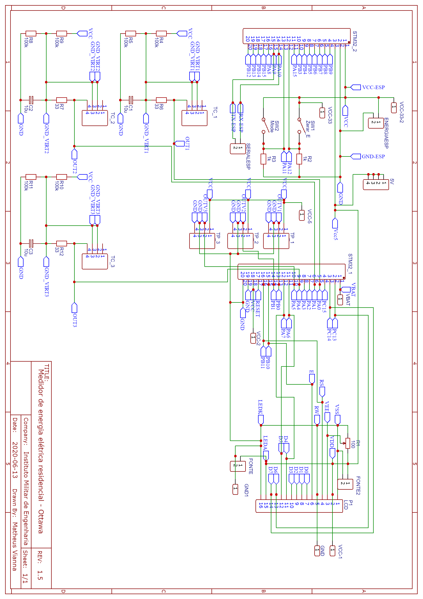
Schematic
The schematic including all the hardware od the power metter.
Schematic
Schematic
The schematic including all the hardware od the power metter.
Schematic
Comments
Only logged in users can leave comments