Wireless Light Therapy (Alzheimer's) Glasses and Lights
A suit of wirelessly interconnected devices to help administer Alzheimer's light therapy to patients.
Devices & Components
3.7V 610mAh Li-Po Battery
3.3v Voltage Regulator
ESP8266 ESP-12E
3V 3A AC Adapter
3V 1W Warm White LED
3.7V 240mAh Li-Po Battery
Male/Male Jumper Wires
3.7V 2000mAh Li-Po Battery
5cm x 7cm Perf Board
NTE 12 High Current PNP Transistor
SSD 1306 I2C 3.3v OLED
Pushbutton switch 12mm
Resistor 330 ohm
Hardware & Tools
Soldering iron (generic)
Rosin Core Solder
Software & Tools
Arduino IDE
Project description
Code
Downloadable files
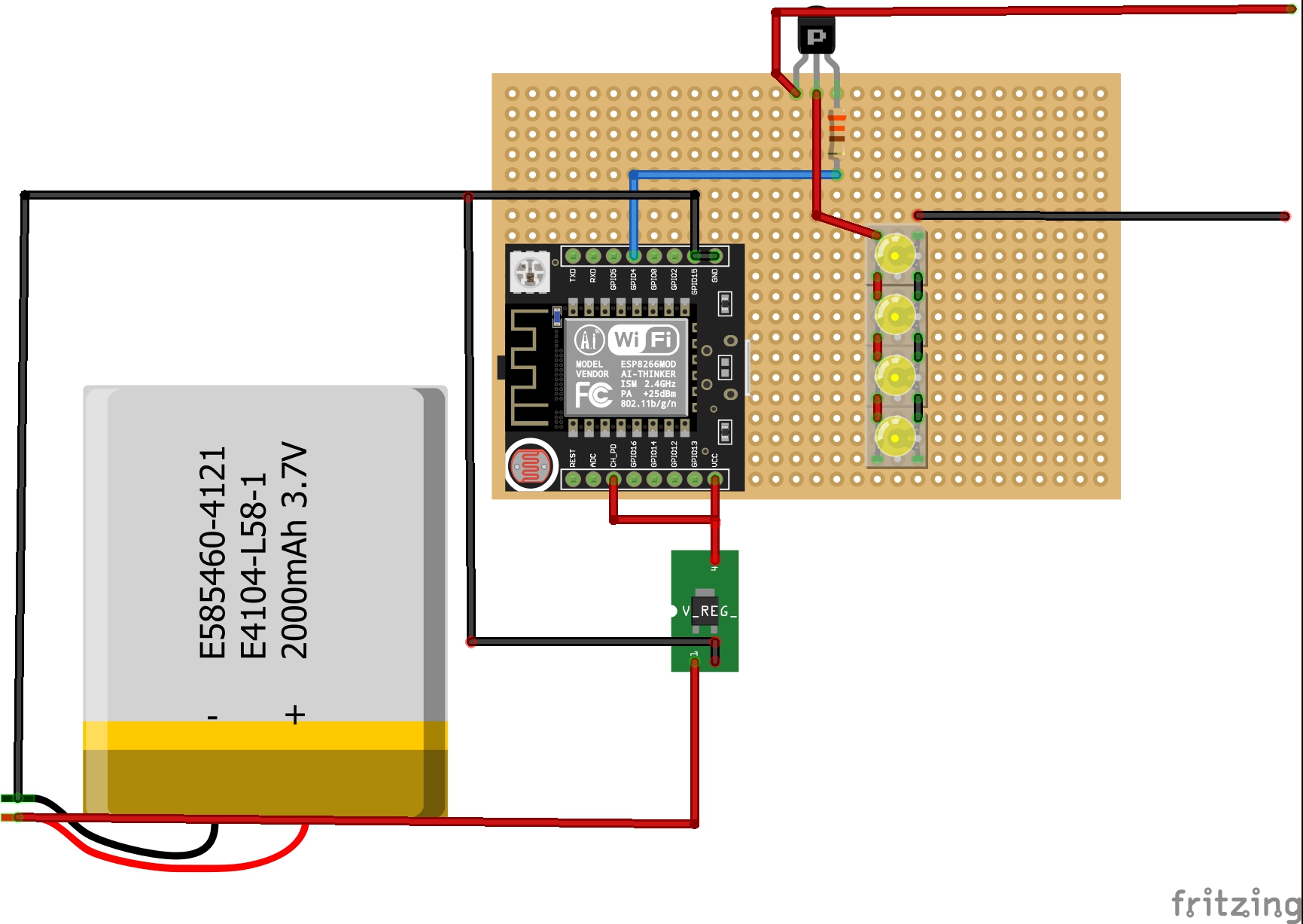
Light Schematic
Schematic detailing how to connect the ESP controlling the main light to the high power LEDs and the NTE12 (PNP transistor, make sure you follow the hookup as shown exactly). The red and black wires going away from the PCB are attached to the anode (+) and cathode (-) of the 3V Power Adapter. PLEASE MAKE SURE YOU DO NOT HAVE THE POWER ADAPTER PLUGGED IN WHILE BUILDING THE CIRCUIT (it has a high power output that can kill you).
Light Schematic
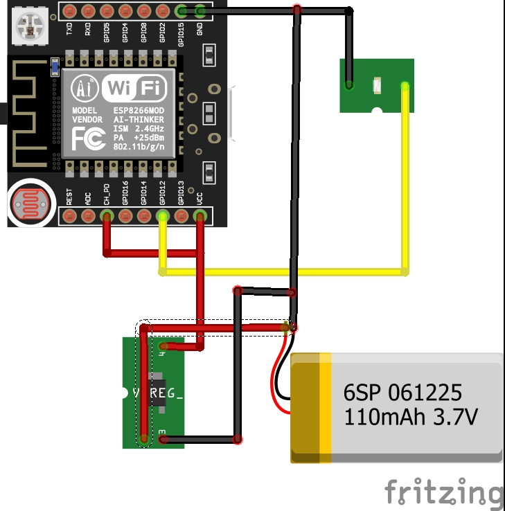
Glasses Schematics
Schematic detailing how to assemble the circuit that gets attached to the glasses. The LED in the schematic should be placed in the corner of the glasses, for visibility by the wearer. The ESP-12f does not look exactly like the one in the schematic, the software that I used did not have the model for a regular ESP-12F, so I used this one
Glasses Schematics
Controller Schematic
The schematic detailing how to assemble the controller with the OLED screen. In reality, the display will take up more space than portrayed. The ESP-12f does not look exactly like the one in the schematic, the software that I used did not have the model for a regular ESP-12F, so I used this one.
Controller Schematic
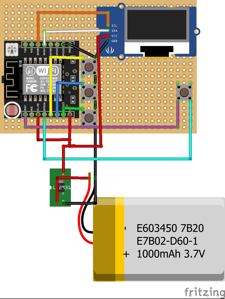
Controller Schematic
The schematic detailing how to assemble the controller with the OLED screen. In reality, the display will take up more space than portrayed. The ESP-12f does not look exactly like the one in the schematic, the software that I used did not have the model for a regular ESP-12F, so I used this one.
Controller Schematic
Light Schematic
Schematic detailing how to connect the ESP controlling the main light to the high power LEDs and the NTE12 (PNP transistor, make sure you follow the hookup as shown exactly). The red and black wires going away from the PCB are attached to the anode (+) and cathode (-) of the 3V Power Adapter. PLEASE MAKE SURE YOU DO NOT HAVE THE POWER ADAPTER PLUGGED IN WHILE BUILDING THE CIRCUIT (it has a high power output that can kill you).
Light Schematic
Glasses Schematics
Schematic detailing how to assemble the circuit that gets attached to the glasses. The LED in the schematic should be placed in the corner of the glasses, for visibility by the wearer. The ESP-12f does not look exactly like the one in the schematic, the software that I used did not have the model for a regular ESP-12F, so I used this one
Glasses Schematics
Comments
Only logged in users can leave comments