Rick & Morty Steampunk Multifunction gadget
Weather station with remote outdoor sense, FM radio, blinkey lights and secret hidden compartment., Magic 8-Ball, Insulin Estimator, etc.
Devices & Components
Arduino Mega 2560 Rev3
WSAH190 2x5W amplifier for MP3 player
RTC DS1302 Real Time Clock Module
Dual Electronics XDM17BT Single DIN Car Stereo , Bluetooth, Siri/Google Assistant , USB, MP3, AM/FM Radio
Prototype Screw/Terminal Block Shield Board Kits Set For Arduino MEGA-2560
28BYJ-48 5V Stepper Motor, 5 wire
DHT11 Temperature & Humidity Sensor (4 pins)
Ultrasonic Sensor - HC-SR04 (Generic)
Linear Regulator (7805)
KY-023 Joystick mounting box
5V Mini Traffic Light Red Yellow Green 5mm LED Display Module
12 Level Stereo LED Indicator VU Meter
5V 4 Channel Relay Board Module Optocoupler LED
WPM402 LM2577 DC-DC VOLTAGE STEP-UP (BOOST) MODULE
Hardware & Tools
Grizzly G0923 3D Printer
Software & Tools
Arduino IDE
NanoCAD
TinkerCAD
Project description
Code
Rick Gadget Box - V5.09 with remote control, magic 8 BALL, & insulin calulator, PO Box Sim
arduino
Fully loaded Mega 2560 Steampunk Rick & Morty Gadget Box. Does bunches of stuff Time/Date Dual 20 x 4 LCD displays, one blue/white, the other yellow/dark Temp/Humidity Joystick State Light/Dark LDR with relay Remote IR operation PO Box Combo Lock with servo control Stepper Motor Control Insulin Estimator Biker Magic 8-ball swami Rangefinder Noise generator Radio VU Meter Blinkey light thing-y If you need RUNNING sample code for most common devices, it's here.
1// 2// Rick Box time/Temp display baseline - Mark M. Lambert - December 3 6, 2021 4// 5// This is an attempt to fully load an Arduino Mega 2560 controller. 6// 7 We're real close to 100% utilization with everything but the kitchen 8// sink 9 installed (it's on back order ...) 10// 11// This is a steampunk, over the top, 12 3d printed, lexan and wood remote control 13// gadget that does lots of things 14 with blinkey lights, remote control and it 15// even plays music. 16// 17// It 18 also acts as biker magic 8-ball and an insulin computer. It reads analogs for 19// 20 the blood sugar number & joystick, turns lights off at dark, knows what time it 21 is, 22// can communicate remotely, switch meter feeds, control blinkey lights, 23 measure 24// distance, and move steppers and servos - all at once! 25// 26// 27 We're down to the last 5 D's, but we still have 8 AI's 28// 29const float Version 30 = 5.09; 31// 32// V5.09 - 11Feb22 - MML - Add insulin estimator & PO Box sim using 33 pot as input device 34// V5.08 - 08Feb22 - MML - Clean up LCD layout 35// V5.07 36 - 07Feb22 - MML - Make 9-ball biker & get VU meter wired 37// V5.06 - 06Feb22 - 38 MML - Add Magic 8-ball 39// V5.05 - 05Feb22 - MML - Get 2nd servo running - All 40 remote buttons working, codes verified 41// V5.04 - 31Jan22 - MML - Stepper fixed 42 - odd phase ordering and setting RPM fixed it 43// V5.03 - 30Jan22 - MML - Servo 44 working, still wirinjg, diddle with stepper 45// V5.02 - 27Jan22 - MML - (Cont.) 46 - Lots working - Echo & clock up, 47// V5.01 - 26Jan22 - MML - (Cont.) 48// V5.00 49 - 24Jan22 - MML - Upgrade IO's (again) 50// V4.03 - 12Jan22 - MML - Test IR remote 51// 52 V4.02 - 11Jan22 - MML - Work on Touch sw & knock 53// V4.01 - 10Jan22 - MML - Try 54 to get hardware to run - everything lights up 55// V4.00 - 08Jan22 - MML - Align 56 I/O's with "as built" hardware 57// V3.01 - 16Dec21 - MML - Get RTC and rangerfinder 58 working 59// V3.00 - 14Dec21 - MML - Get 2nd lcd working 60// V2.00 - 13Dec21 61 - MML - Strip down to get clean compile 62// V1.01 - 10Dec21 - MML - Continue baseline 63// 64 V1.00 - 06Dec21 - MML - Baseline with LCD - Mega 2650 has built in pullups 65// 66// 67 ---------------------------------------------------------------------------- 68// 69 ---------------------------------------------------------------------------- 70// 71// 72 Device Master List 73// 74// Mega 2560 Processor 75// +12 to +5 Vreg 76 & Buss Bars 77// I2C devices 78// 1602 LCD Command display 79// 2004 80 LCD #1 Indoor Display 81// 2004 LCD #2 Outdoor Display 82// BHT280 83 Baro Barometric sensor 84// 85// Echo Rangefinder 86// Traffic Light 87// 88 FM Radio (Button) <<====== OUT - Real Radio in 89// Analog VU meter Subsystem 90// 91 IR remote command in 92// LDR light sensor 93// Analog Joystick with push sw 94// 95// 96 K1-4, 5, & 6 relays 97// RTC 98// DHT11 Temp/Humidity (Indoor) 99// ESP-01 WiFi 100 - From Outdoor DHT-11 101// Touch Sensor 102// Servo output - Haven't added IO's 103 yet or quite figured out what this will do. 104// I'm leaning to a secret compartment 105 with a hidden release and maybe the knock sensor 106// Knock sensor 107// 108// 109 ================================== 110// Start of Pin Constants 111// ================================== 112// 113// 114 Analogs first 115// 116int xx = 0; //Placeholder value 117// 118const 119 int Vnoise = A2; // Random number seed is open AI 120const int Vin = A3; 121 //Power supply direct output monitor - NOT USED 122// 123const int I2C_A4 = 124 A4; // RESERVED 125const int I2C_A5 = A5; // RESERVED 126// 127// Float constant 128// 129const 130 float VoltsPerBit = (5.0 / 1024.0); //Compute bit weight based on +5 Vin max 131// 132// 133 Int constant implied 134// 135const int VinAux5 = A12; //+5v input monitor via 136 card 137// 138// Joystick - A13 & 14 not on Uno 139// See Also Zaxis DI 140// 141const 142 int Yaxis = A13; //Joystick y 143const int Xaxis = A14; //Joystick X 144// 145const 146 int Wiper = A15; //Wiper from 5k pot 147// 148// Analogs end 149// ----------- 150// 151 Now digitals 152// 153// D0 and D1 are rx/tx for serial programming 154// 155const 156 int RPM = 15; // Top end is ~15 from what I've read, works at 157 15 158const int StepsPerRevolution = 2048; // 28BYJ-48 Stepper - this # may not 159 be exact, docs differ 160// 161// Stepper motor pins - Powered by Aux +5 - Works! 162// 163const 164 int StepA = 2; //Stepper Motor Phase A 165const int StepB = 3; //Stepper 166 Motor Phase B 167const int StepC = 4; //Stepper Motor Phase C 168const int 169 StepD = 5; //Stepper Motor Phase D 170// 171// 6/7 L & R PWM 172// 173const 174 int VULeft = 6; // Signal to VU meter Left 175const int VURight = 7; // 176 Ditto right 177// 178const int MotorSpeed = 8; // PWM for motor speed control 179 180// 181// Servo needs a PWM output. Powered by Aux +5 182// 183const int PWM1 184 = 9; // Big servo 185const int PWM2 = 10; // Small servo - needs 186 test 187// 188// 11 & 12 RFU 189// 190const int LEDPin = 13; // Built in LED 191// 192// 193 Comm channel I/O's are given 194// 195const int S3_TX = 14; //ESP-01 WiFi 196 - needs test 197const int S3_RX = 15; 198// 199const int S2_TX = 16; //Button 200 radio <<=== Not used 201const int S2_RX = 17; 202// 203const int S1_TX = 204 18; //Knob radio BACK IN! ***** 205const int S1_RX = 19; 206// 207// I2C 208 is brought out to buss bars for mass connections 209// We have at least five I2C 210 devices on the buss. three LCD's, the RTC, and the BM-280 baro chip 211// Device 212 addresses have been jumper preset on LCD's 213// 214// Actually the buss bars are 215 connected thru the SDA/SCL pins by D13, not these 216// 217const int I2C_SDA = 218 20; // These are attached to the matching buss bars for bussing to all I2C devices 219const 220 int I2C_SCL = 21; // Pullups are internal to Mega 2560 221// 222// 22-25 reserved 223 for MOSI/MISO SP1 devices 224// 225// 11Feb22 226// Got dot matrix and 4 digit readouts 227 on order. 228// The matrix needs MOSI and I think the readouts 229// are I2C, but 230 I won't be sure until they arrive 231// 232// Alternative Pins Function: 233// SPI 234 Pins: 235// 236// Pin 22 - SS 237// Pin 23 - SCK 238// Pin 24 - MOSI 239// Pin 240 25 – MISO 241// 242// See also pins 51-53 243// 244const int SSX = 22; 245const 246 int SCKX = 23; 247const int MOSIX = 24; 248const int MISOX = 25; 249// 250// 251 RTC I/O pins - Working fine - Use SET_CLOCK project to preset time 252// 253// Set 254 the appropriate digital I/O pin connections. These are the pin 255// assignments 256 for the Arduino as well for as the DS1302 chip. See the DS1302 257// datasheet: 258// 259// 260 http://datasheets.maximintegrated.com/en/ds/DS1302.pdf 261// 262const int kCePin 263 = 26; // Chip Enable 264const int kIoPin = 27; // Input/Output 265const 266 int kSclkPin = 28; // Serial Clock 267// 268// H drive Circuit still under development 269// 270const 271 int MotorOn = 29; //DC motor on/off - plan is two outputs, direction and enable 272const 273 int MotorDir = 30; //DC motor Direction - plan is to add H drive circuit 274// 275// 276 Need a PWM for MotorSpeed - D8 277// 278const int TL2_R = 31; 279const int TL2_Y 280 = 32; 281const int TL2_G = 33; 282// 283// Singleton relay Modules 284// 285const 286 int K5 = 34; // Left Audio - Powered by Aux +5 287const int K6 = 288 35; // Right Audio - Powered by Aux +5 289// 290// Humidity/temp sensors 291// 292const 293 int DHTPIN = 36; // Digital pin connected to the DHT sensor 294// 295// IR 296 remote control input 297// 298const int RECV_PIN = 37; //IR Receiver input 299 pin 300// 301// There are seven rows of three buttons each. Each has (presumably) 302// 303 a unique code. We're going to define the button codes here instead 304// of scattering 305 them in a massive SWITCH. 306// 307// ---------------------- 308// _00 = _RC, 0 309 indexed 310// 311// All the little IR remotes appear to use the same set of codes 312// 313 Determined empirically: 314// 315const int Btn_00 = 23971; // Top Row, left button 316 - Row 0, Col 0 317const int Btn_01 = 25245; // Row 0, Col 1 - 318const int Btn_02 319 = 7651; // Top Row, right button - Row 0, Col 2 320// 321const int Btn_10 = 322 8925; // Row 1, col 0 - (red) 323const int Btn_11 = 765; 324const int Btn_12 325 = 15811; 326// 327const int Btn_20 = 8161; 328const int Btn_21 = 22441; 329const 330 int Btn_22 = 28561; 331// 332const int Btn_30 = 26775; 333const int Btn_31 = 334 26521; 335const int Btn_32 = 20401; 336// 337const int Btn_40 = 12495; 338const 339 int Btn_41 = 6375; 340const int Btn_42 = 31365; 341// 342const int Btn_50 = 4335; 343const 344 int Btn_51 = 14535; 345const int Btn_52 = 23205; 346// 347const int Btn_60 = 348 17085; 349const int Btn_61 = 19125; 350const int Btn_62 = 21165; // Bottom 351 Row, right button 352// ---------------------- 353// 354const int TouchSw = 38; 355 //Touch switch - Needs debounce 356// 357// Quad Relay board pins - Powered 358 By Aux +5 Via Jumper 359// 360const int K1 = 39; // VU Meter power - 361 Not yet wired 362const int K2 = 40; // VU Mode Button Select - Not yet 363 wired 364const int K3 = 41; // Decoration lighting control 365const int 366 K4 = 42; // Sundown Relay - Follows LDR input 367// 368const int KnockSw 369 = 43; // Knock switch - This and TouchSw activate together to rotate servo 370 90 deg 371// 372// Joystick switch 373// 374const int Zaxis = 44; // Joystick 375 Z (push sw) 376// 377// LDR 378// 379const int LDR_IN = 45; // LDR w/ comparator 380 input 381// 382// Sonar pins HC-SRO4 - Wired backwards it faulted the +5 but didn't 383 burn out. 384// Just lucky I guess 385// 386const int echoPin = 46; 387const int 388 trigPin = 47; 389// 390// Traffic light shows distance - range is limited 391// 392const 393 float DistFar = 18.0; // Green 394const float DistMed = 12.0; // Yellow 395const 396 float DistNear = 6.0; // Red 397// 398// Needs to move for MOSI/MISO support 399// 400// 401 Traffic lights are at top end of DOs 402// 403const int TL_R = 48; //As 404 of V5 405const int TL_Y = 49; 406const int TL_G = 50; // <<== Overlap 407 with MISO ********** 408// 409// See also pins 21-25 410// 51-53 not used - reserved 411 for MOSI/MISO 412// SPI: 413// 50/25 (MISO) <<== not needed for output only 414// 415 51/24 (MOSI) 416// 52/23 (SCK) 417// 53/22 (SS) <<== Device Select 418// 419// 420 ================================== 421// End of Pin Constants 422// ================================== 423// 424// 425 Device Constants 426// 427const unsigned interval = 500; // Half second pulse 428// 429// 430 LCD geometry 431// Smaller display 432// 433const int LCD_COLS = 16; 434const int 435 LCD_ROWS = 2; 436// 437// Bigger display 438// 439const int LCD_COLS2 = 20; 440const 441 int LCD_ROWS2 = 4; 442// 443// ---------------------------------------------------------------------------- 444// 445 ---------------------------------------------------------------------------- 446// 447// 448 Includes - DO NOT REORDER 449// 450#include <stdio.h> 451#include <DHT.h> //Digital 452 Humidity/Temp sensor library 453#include <DS1302.h> //RTC library 454#include 455 <IRremote.h> //IR Remote Library 456// 457// These three includes MUST be in 458 this order or wierd "Error compiling for board Arduino Mega or Mega 2560." error 459// 460 Wire.h must load first 461// 462#include <Wire.h> //I2C Driver 463#include 464 <LiquidCrystal_I2C.h> //I2C LCD display driver for all LCD's 465#include <Servo.h> 466 //PWM Servo motor 467#include <Stepper.h> //Four Phase 468 stepper motor 469// 470// 471// BMP280 stuff 472// 473#include <SPI.h> // 474 ??? 475#include <Adafruit_BMP280.h> //Baro I2C sensor 476// 477#define BMP_SCK 478 (13) // Not using MISO/MOSI, am I? 479#define BMP_MISO (12) 480#define 481 BMP_MOSI (11) 482#define BMP_CS (10) 483// 484Adafruit_BMP280 bmp; // I2C 485// 486// 487 ---------------------------------------------------------------------------- 488// 489 ---------------------------------------------------------------------------- 490// 491Servo 492 DoorServo; // create servo object to control large servo 493Servo AuxServo; // 494 create servo object to control small servo 495// 496// Invoke LCD objects 497// 498 Currently only #2 and #3 are used 499// 500LiquidCrystal_I2C lcd1(0x3E, LCD_COLS, 501 LCD_ROWS ); // set the LCD1 object address to 0x3E for a 16 chars and 2 line 502 display 503LiquidCrystal_I2C lcd2(0x25, LCD_COLS2, LCD_ROWS2); // set the LCD2 504 object address to 0x25 for a 20 chars and 4 line display 505LiquidCrystal_I2C lcd3(0x26, 506 LCD_COLS2, LCD_ROWS2); // set the LCD3 object address to 0x27 for a 20 chars and 507 4 line display 508// LiquidCrystal_I2C lcd4(0x27, LCD_COLS2, LCD_ROWS2); // set 509 the LCD4 object address to 0x25 for a 20 chars and 4 line display (Not installed) 510// 511// 512 Create a DS1302 RTC object. 513// 514DS1302 rtc(kCePin, kIoPin, kSclkPin); 515// 516 Turn clock on after power up 517// 518// Temp/Humidity 519// 520// Uncomment whatever 521 type you're using! 522#define DHTTYPE DHT11 // DHT 11 523//#define DHTTYPE DHT22 524 // DHT 22 (AM2302), AM2321 525//#define DHTTYPE DHT21 // DHT 21 (AM2301) 526// 527int 528 valx = 0; // variable to store the value read 529// 530DHT dht(DHTPIN, DHTTYPE); 531 // Create Object 532// 533// Stepper motor object. Note odd order: A/C/B/D 534// 535Stepper 536 MotorStepper(StepsPerRevolution, StepA, StepC, StepB, StepD); 537// 538// IR Remote 539 control object 540// 541IRrecv irrecv(RECV_PIN); // Build IR receiver object 542decode_results 543 results; // Not sure about this, but it works 544// 545// ------------------------- 546// 547 Objects built 548// ------------------------- 549// 550// Fancy footwork needed 551 to run instead of using Delay 552// 553// Global state flags 554// 555int EchoFlag 556 = true; // Enables rangefinder 557// 558const int VURadio = false; 559const int 560 VUPWM = true; 561// 562// K5/6 state tracks this 563int VUMode = VURadio; 564// 565// 566 LCD states 567// 568int lcd1light = true; 569int lcd2light = true; 570int lcd3light 571 = true; 572// 573unsigned long previousMillis = 0; // will store last time 574 LED was updated 575// 576// Define strings for PO Box Combo Lock simulator 577// 578 20 lock postitions 579const int LockAngle = 15; 580const int UnLockAngle = LockAngle 581 + 79; //Desired rotation angle to open door 582const int MidAngle = (LockAngle 583 + UnLockAngle) /2; 584int LockSteps = 20; //Number of LockTable entries 585char 586 *LockTable[] = { 587 "A", 588 "A-B", 589 "B", 590 "B-C", 591 592 "C", 593 "C-D", 594 "D", 595 "D-E", 596 "E", 597 598 "E-F", 599 "F", 600 "F-G", 601 "G", 602 "G-H", 603 604 "H", 605 "H-I", 606 "I", 607 "I-J", 608 "J", 609 610 "J-A" 611 }; 612// 613// ============================================ 614// 615 SETUP 616// ============================================ 617// 618void setup() 619 620 { 621 // 622 // seed random number generator with noise 623 // 624 randomSeed(analogRead(Vnoise)); 625 // floating input is seed 626 // 627 // Set stepper speed - not in all examples 628 but required 629 // 630 MotorStepper.setSpeed(RPM); // RPM slew rate 631 // 632 633 // Fire up servos 634 // 635 DoorServo.attach(PWM1); // attaches the Large 636 servo pin to the servo object 637 AuxServo.attach(PWM2); // attaches the Small 638 servo pin to the servo object 639 DoorServo.write(LockAngle); // Default to 640 locked position 641 AuxServo.write(LockAngle); 642 // 643 // Fire up RTC 644 645 // 646 rtc.writeProtect(false); //Gotta unlock before letting it run 647 rtc.halt(false); 648 //Let clock run 649 rtc.writeProtect(true); //Only protect AFTER letting 650 it run 651 // 652 Serial.begin(9600); //Warm up comm port 653 // 654 // 655 INPUT is default but we need to make sure they don't float with INPUT_PULLUP 656 657 // Declare all inputs as pullups 658 // 659 pinMode(KnockSw, INPUT_PULLUP); 660 //Knick Switch 661 pinMode(TouchSw, INPUT_PULLUP); //Touch Switch 662 663 pinMode(LDR_IN, INPUT_PULLUP); //Light dark 664 pinMode(Zaxis, INPUT_PULLUP); 665 //Push sw on joystick 666 // 667 // Relays 668 // 669 pinMode(K1, OUTPUT); 670 671 pinMode(K2, OUTPUT); 672 pinMode(K3, OUTPUT); 673 pinMode(K4, OUTPUT); 674 pinMode(K5, 675 OUTPUT); 676 pinMode(K6, OUTPUT); 677 // 678 digitalWrite(K1, HIGH); //Turn 679 off - Negative logic 680 digitalWrite(K2, HIGH); //Turn off 681 digitalWrite(K3, 682 HIGH); //Turn off 683 digitalWrite(K4, HIGH); //Turn off 684 digitalWrite(K5, 685 LOW); //Turn off - positive logic 686 digitalWrite(K6, LOW); //Turn off 687 688 // 689 pinMode(LED_BUILTIN, OUTPUT); 690 digitalWrite(LED_BUILTIN, LOW); //Turn 691 off 692 // 693 // Traffic lights 694 // 695 pinMode(TL_G, OUTPUT); 696 pinMode(TL_Y, 697 OUTPUT); 698 pinMode(TL_R, OUTPUT); 699 // 700 pinMode(TL2_G, OUTPUT); 701 pinMode(TL2_Y, 702 OUTPUT); 703 pinMode(TL2_R, OUTPUT); 704 // 705 digitalWrite(TL_G, LOW); //Turn 706 off 707 digitalWrite(TL_Y, LOW); //Turn off 708 digitalWrite(TL_R, LOW); 709 //Turn off 710 // 711 digitalWrite(TL2_G, LOW); //Turn off 712 digitalWrite(TL2_Y, 713 LOW); //Turn off 714 digitalWrite(TL2_R, LOW); //Turn off 715 // 716 // 717 Sonar I/O 718 // 719 pinMode(trigPin, OUTPUT); 720 pinMode(echoPin, INPUT_PULLUP); 721 722 // 723 // Pins all set, anything not listed is a hi-Z input 724 // 725 // ============ 726 727 // 728 // Turn on IR remote 729 // 730 irrecv.enableIRIn(); 731 // 732 dht.begin(); 733 //Fire up temp/humidity sensor 734 //Serial.print("DHT pin: "); 735 //Serial.println(DHTPIN); 736 737 // 738 // Serial.println("Init 1602 LCD"); 739 // Serial.println("LCD 1 740 test"); 741 // Print a message to the 1602 LCD 742 lcd1.clear(); 743 lcd1.print("Hello, 744 Mark!"); 745 delay(1500); // wait a bit to see it 746 lcd1.setCursor(0, 1); 747 748 lcd1.print("Hello, Again!"); 749 // 750 // Serial.println("LCD 2 test"); 751 752 // 753 // Three LCD's - show something on 2004's 754 // 755 lcd2.init(); //initialize 756 the lcd 757 lcd2.backlight(); //open the backlight 758 lcd2.setCursor ( 0, 0 759 ); // go to the top left corner 760 lcd2.print("Hello, Mark!"); 761 762 lcd2.setCursor ( 0, 1 ); // go to the 2nd row 763 lcd2.print("Mark's 764 Next Idea!"); 765 lcd2.setCursor ( 0, 2 ); 766 lcd2.print("Rick & Morty Box!"); 767 768 lcd2.setCursor ( 3, 3 ); // go to the 4th row 769 lcd2.print("Version: 770 "); 771 lcd2.print(Version); 772 // 773 Serial.println("LCD 3 test"); 774 775 lcd3.init(); //initialize the lcd 776 lcd3.backlight(); //open the backlight 777 778 lcd3.setCursor ( 0, 0 ); // go to the top left corner 779 lcd3.print("Hello, 780 Mark!"); // write this string on the top row 781 lcd3.setCursor ( 0, 1 ); // 782 go to the top left corner 783 lcd3.print("LCD #3"); // write this string on the 784 top row 785 lcd3.setCursor ( 3, 3 ); // go to the 4th row 786 lcd3.print("Version: 787 "); 788 lcd3.print(Version); 789 // 790 delay(2000); // wait a bit to see it 791 792 // 793 // RTC init 794 // Initialize a new chip by turning off write protection 795 and clearing the 796 // clock halt flag. These methods needn't always be called. 797 See the DS1302 798 // datasheet for details. 799 // 800 // Turn clock on after 801 power up 802 // 803 rtc.writeProtect(false); 804 rtc.halt(false); 805 rtc.writeProtect(true); 806 807 // 808 // BMP-180 or -280 init 809 // 810 /* Default settings from datasheet. 811 */ 812 bmp.setSampling(Adafruit_BMP280::MODE_NORMAL, /* Operating Mode. */ 813 814 Adafruit_BMP280::SAMPLING_X2, /* Temp. oversampling */ 815 816 Adafruit_BMP280::SAMPLING_X16, /* Pressure oversampling */ 817 818 Adafruit_BMP280::FILTER_X16, /* Filtering. */ 819 Adafruit_BMP280::STANDBY_MS_500); 820 /* Standby time. */ 821 // 822 lcd2.clear(); 823 lcd3.clear(); 824 Serial.println("Setup 825 Complete"); 826 } 827// ============================================ 828// 829// 830 SETUP ends 831// 832// ============================================ 833// ============================================ 834// 835// 836 LOOP BEGINS 837// 838// ============================================ 839/* 840 * 841 The idea here is to trigger different functions with the remote 842 * The Temp/Humidity, 843 time, distance, etc are selectively displayed on command 844 * Everything but the 845 RTC is curretly connected. 846 */ 847 // Globals 848int LastTouch = LOW; // Hope 849 this scope is universal 850int LastLDR = LOW; 851int Coin = LOW; 852String 853 IRval; 854String LastIRCmd; 855// 856// Declaring vars inside SWITCH blows up 857// 858const 859 int MaxUnitsN = 60; // Hard code for now 860int minsTo12 = 0; //12 861 * 60 = 720 max 862int UnitsN = 0; 863int UnitsR = 0; 864// 865 int valx = 0; 866int xxx = random(27); 867int Rdg 868 = analogRead(Wiper) / 3; 869Time t = rtc.time(); 870 // Device data type 871// 872// Fall into runtime 873// 874void loop() 875 876 { 877 // 878 // Fast execution items lead 879 // 880 digitalWrite(TL_G, digitalRead(KnockSw)); 881 // Works! 882// digitalWrite(TL_G, digitalRead(TouchSw)); // Works - sorta 883 884 // 885 // Servo needs to be responsive Move on both sides of clock tick 886 // 887// 888 MoveServo(); //Move servo to follow pot - for test 889// MotorStepper.step(205); 890 // Spin stepper for test 891 // 892 // Watch LDR and toggle accordingly 893 894 // Actually we should only act on changes 895 // 896 int CurrentState = digitalRead(LDR_IN); 897 898 // 899 if (CurrentState != LastLDR) 900 { 901 LastLDR = CurrentState; 902 903 if (CurrentState == HIGH) 904 { 905// lcd2.clear(); // 906 Clear before update 907// lcd3.clear(); 908 digitalWrite(TL_Y, HIGH); 909 // turn the LED on (HIGH is the voltage level) 910 digitalWrite(K4, LOW); 911 // turn the relay off during the day 912 lcd3.setCursor(0, 1); 913 lcd3.print("Dark 914 "); // Trailing blank needed to cover the T in lighT 915 } 916 else 917 918 { 919 digitalWrite(TL_Y, LOW); // turn the LED on (HIGH is the voltage 920 level) 921 digitalWrite(K4, HIGH); // turn the relay on at night (HIGH is 922 the active voltage level) 923 lcd3.setCursor(0, 1); 924 lcd3.print("Light"); 925 // 926 } 927 // 928 } 929 // 930 // This is tic-toc timer - 931 items here are polled once a second 932 // Tic is first half of second, toc is 933 last half. 934 // 935 unsigned long currentMillis = millis(); 936 // 937 if 938 (currentMillis - previousMillis >= interval) 939 { 940 // 941 // Here 942 every 500 ms 943 // 944 // save the last time you blinked the LED 945 // 946 947 previousMillis = currentMillis; 948 // 949 // if the LED is off turn it 950 on and vice-versa: 951 // 952 if (Coin != HIGH) 953 { 954 // 955 956 // Tic 1/2 sec 957 // 958 Coin = HIGH; 959 digitalWrite(LED_BUILTIN, 960 HIGH); // turn the heartbeat led on 961 digitalWrite(TL_R, HIGH); //Turn 962 on 963 lcd2.setCursor(19, 3); 964 lcd2.print("|"); //Tick Symbol 965 966 } 967 else 968 { 969 // 970 // toc 1/2 sec 971 // 972 973 Coin = LOW; 974 // 975 digitalWrite(LED_BUILTIN, LOW); // turn 976 the heartbeat LED off 977 digitalWrite(TL_R, LOW); //Turn off 978 lcd2.setCursor(19, 979 3); 980 lcd2.print("-"); //Tock Symbol 981 // 982 // Touch 983 SW 984 // Actually we should only act on changes 985 // Still not working 986 right 987 // 988 /* 989 int NewState = digitalRead(TouchSw); 990 991 // 992 // Act on rising edge only 993 // 994 if ( (NewState 995 != LastTouch) && (NewState == HIGH) ) 996 { 997 LastTouch = NewState; 998 999 Serial.print(NewState); 1000 1001 if (digitalRead(K4) != HIGH) 1002 1003 { 1004 digitalWrite(K4, HIGH); // Touchy if running fast. only 1005 poll once a second to debounce 1006 digitalWrite(TL_G, LOW); // Touchy 1007 if running fast. only poll once a second to debounce 1008 Serial.println("Touch 1009 Off"); 1010 } 1011 else 1012 { 1013 digitalWrite(K4, 1014 LOW); // Touchy if running fast. only poll once a second to debounce 1015 digitalWrite(TL_G, 1016 HIGH); // Touchy if running fast. only poll once a second to debounce 1017 Serial.println("Touch 1018 On"); 1019 } 1020 1021 // 1022 } 1023 */ 1024 // 1025 1026 // Here every second ... We should load balance but for diags we run 1027 // 1028 all subs at once 1029 // 1030 // All of these work with correct IO assignments 1031 1032 // 1033 ShowTime(); // Works! 1034 Read_DHT(); // Read/display 1035 temp/humidity 1036 RangeFinder(); // Compute range to target - I think I 1037 blew the sensor 1038 FindJoy(); // read joystick 1039 ShowAnalog(); 1040 // Display input voltages 1041 // 1042 // **************************************** 1043 1044 // Bottom of Tic-Toc before IR remote added 1045 // **************************************** 1046 1047 // 1048 // Both fast and slow I/O's have been polled 1049 // IR remote 1050 code is big switch. There are 21 different buttons with unique responses 1051 // 1052 1053 // IR Remote needs to be shielded from other light sources 1054 // Umm 1055 dunno how fast we should poll this. Its fast polling now. 1056 // but we might 1057 need to slow it down 1058 // 1059 CheckIR(); 1060 // 1061 } // 1062 End of tic/tock 1063 // 1064 } // End of currentmills 1065 // 1066 } // 1067 End of LOOP 1068// ============================================================================= 1069// 1070 ============================================================================= 1071// 1072 Functions 1073// ============================================================================= 1074// 1075 ============================================================================= 1076// 1077 ====================================================== 1078// 1079// Function to read 1080 and display Temp Humidity from sensor 1081// 1082void Read_DHT() 1083 { 1084 float 1085 h, f; 1086 // 1087 // Reading temperature or humidity takes about 250 milliseconds! 1088 1089 // Sensor readings may also be up to 2 seconds 'old' (its a very slow sensor) 1090 1091 // 1092 h = dht.readHumidity(); 1093 // Read temperature as Celsius (the default) 1094 1095 // t = dht.readTemperature(); 1096 // Read temperature as Fahrenheit (isFahrenheit 1097 = true) 1098 f = dht.readTemperature(true); 1099 // 1100 // Display on LCD'S 1101 1102 // 1103 // LCD2 is outdoor data - eventually - gotta build the remote first LOL 1104 1105 // 1106 lcd2.setCursor ( 0, 2 ); // go to the 3rd row 1107 lcd2.print(String(h, 1108 1) + "%"); 1109 lcd2.setCursor ( 0, 3 ); // go to the fourth row 1110 1111 lcd2.print(String(f, 1) + "F"); 1112 // 1113 // LCD3 is indoor data 1114 // 1115 1116 lcd3.setCursor ( 0, 2 ); // go to the 3rd row 1117 lcd3.print(String(h, 1118 1) + "%"); 1119 lcd3.setCursor ( 0, 3 ); // go to the fourth row 1120 1121 lcd3.print(String(f, 1) + "F"); 1122 // 1123 } 1124// 1125// End of Read_DHT() 1126// 1127// 1128 ======================================= 1129// 1130// MoveServo to where pot tells 1131 it to go 1132// 1133void MoveServo() 1134 { 1135 int valx = analogRead(Wiper); // 1136 reads the value of the potentiometer (value between 0 and 1023) 1137 valx = map(valx, 1138 0, 1023, 0, 180); // scale it for use with the servo (value between 0 and 180) 1139 1140 DoorServo.write(valx); // sets the servo position according to 1141 the scaled value 1142 AuxServo.write(valx); // Both servos track 1143 for test 1144 lcd2.setCursor ( 10, 1 ); // go to the 3rd row 1145 lcd2.print(valx); 1146 1147 lcd2.print(" Deg "); 1148 } 1149// ======================================= 1150// 1151// 1152 RTC Print time 1153// 1154void ShowTime() 1155 { 1156 // Get the current time and 1157 date from the chip. 1158 t = rtc.time(); 1159 // Name the day of the week. 1160 // 1161 const String day = dayAsString(t.day); 1162 // Format the time and date and insert 1163 into the temporary buffer. 1164 char buf[50]; 1165 snprintf(buf, sizeof(buf), "%04d-%02d-%02d 1166 %02d:%02d:%02d", 1167 t.yr, t.mon, t.date, 1168 t.hr, t.min, 1169 t.sec); 1170 // 1171 // Print the formatted string to serial so we can see the time. 1172 1173 // Update both displays so time is always visible 1174 // 1175 lcd1.setCursor(0, 1176 0); 1177 lcd1.print(buf); 1178 // 1179 lcd2.setCursor(0, 0); 1180 lcd2.print(buf); 1181 1182 // 1183 lcd3.setCursor(0, 0); 1184 lcd3.print(buf); 1185 } 1186// ================================================== 1187// 1188// 1189 Range finder 1190// 1191void RangeFinder() 1192{ 1193// 1194// Check to see if we should 1195 run at all 1196// 1197const int Tol = 1; // Overlap between limits 1198if (EchoFlag 1199 != false) 1200 { 1201 // Serial.println("Ping!"); 1202 float duration, distance, 1203 distinch; 1204 // 1205 digitalWrite(trigPin, LOW); 1206 delayMicroseconds(2); 1207 1208 digitalWrite(trigPin, HIGH); 1209 delayMicroseconds(10); 1210 digitalWrite(trigPin, 1211 LOW); 1212 // 1213 duration = pulseIn(echoPin, HIGH); 1214 distance = (duration 1215 * .0343) / 2; 1216 distinch = (distance / 2.54); //Cm to inches 1217 // 1218 // 1219 Filter noise 1220 // 1221 if ((distance > 1.0 ) && (distance< 100.0)) // Inside 1222 Range gate? 1223 { 1224 // 1225 lcd2.setCursor(0, 1); 1226 lcd2.print(" 1227 "); 1228 lcd2.setCursor(0, 1); 1229 lcd2.print(String(distinch, 1230 1)); 1231 lcd2.print(" in."); 1232 // 1233 if ( (distinch <= DistFar) && 1234 (distinch > DistMed) ) 1235 { 1236 digitalWrite(TL2_G, HIGH); 1237 } 1238 1239 else 1240 { 1241 digitalWrite(TL2_G, LOW); 1242 } 1243 // 1244 1245 if ( (distinch <= DistMed) && (distinch > DistNear) ) 1246 { 1247 digitalWrite(TL2_Y, 1248 HIGH); 1249 } 1250 else 1251 { 1252 digitalWrite(TL2_Y, LOW); 1253 1254 } 1255 // 1256 if (distinch <= DistNear) 1257 { 1258 digitalWrite(TL2_R, 1259 HIGH); 1260 } 1261 else 1262 { 1263 digitalWrite(TL2_R, LOW); 1264 1265 } 1266 // 1267 } 1268 else 1269 { 1270 // We're Out Of Range - say 1271 so 1272 lcd2.setCursor(0, 1); 1273 lcd2.print("OOR "); 1274 1275 // 1276 // All off ? 1277 // This may cause flicker 1278 // 1279 1280 digitalWrite(TL2_R, LOW); 1281 digitalWrite(TL2_Y, LOW); 1282 digitalWrite(TL2_G, 1283 LOW); 1284 } // Range gate closes 1285 // 1286 } // Enable gate closes 1287else 1288 1289 { 1290 // We're Off - update screen 1291 lcd2.setCursor(0, 1); 1292 lcd2.print("Off 1293 "); 1294 // 1295 digitalWrite(TL2_R, LOW); 1296 digitalWrite(TL2_Y, 1297 LOW); 1298 digitalWrite(TL2_G, LOW); 1299 // 1300 } 1301 // 1302} 1303// ================================================== 1304// 1305// 1306 FindJoy - Read joystick analogs - Tested - Works 1307// 1308void FindJoy() 1309 { 1310 1311 // char tmp[80]; 1312 int x, y; 1313 x = analogRead(Xaxis); 1314 y = analogRead(Yaxis); 1315 1316 // 1317 String tmp = String(x); 1318 tmp = tmp + "X/"; 1319 tmp = tmp + String(y); 1320 1321 tmp = tmp + "Y"; 1322 // Serial.println(tmp); 1323 lcd2.setCursor(6, 2); 1324 1325 // "----X/----Y UP" <= 14 chars 1326 lcd2.print(" "); // <= 14 1327 chars 1328 lcd2.setCursor(6, 2); 1329 lcd2.print(tmp); // Col 7, row 3 + 14 1330 chars just fits on 20 char line 1331 // 1332 // Print cursor is where tmo ended, 1333 tack on tail 1334 // 1335 if (digitalRead(Zaxis) != 0) 1336 { 1337 lcd2.print(" 1338 UP"); 1339 } 1340 else 1341 { 1342 lcd2.print(" DN"); 1343 } 1344 1345 // 1346 } // End of FindJoy 1347// ================================================== 1348// 1349// 1350 ShowAnalog - Read voltage analog 1351// 1352void ShowAnalog() 1353 { 1354 int VoltageRaw 1355 = analogRead(VinAux5); // Not yet wired 1356 String tmp = String(VoltageRaw * 1357 VoltsPerBit, 1) + "V"; 1358 lcd3.setCursor(15, 1); 1359 lcd3.print(" "); 1360 1361 lcd3.setCursor(15, 1); 1362 lcd3.print(tmp); 1363 // 1364 // Read & Display pot 1365 wiper - Currently driving servo position 1366 // 1367 VoltageRaw = analogRead(Wiper); 1368 1369 tmp = String(VoltageRaw * VoltsPerBit, 1) + "V"; 1370 lcd3.setCursor(15, 2); 1371 1372 lcd3.print(" "); 1373 lcd3.setCursor(15, 2); 1374 lcd3.print(tmp); 1375 // 1376 1377 // This input is scaled down by a factor of 5 due to input card. 1378 // This 1379 input monitors the internal Aux +5 power buss that powers the relays, motors, servos, 1380 etc. 1381 // 1382 VoltageRaw = analogRead(VinAux5); // Aux +5 powers motors 1383 1384 // 1385 float Work = VoltageRaw * VoltsPerBit * 5; 1386 // 1387 float Nominal 1388 = 5.0; 1389 float Tolerance = 0.2; //In Spec band 1390 // 1391 // Keep tmp 1392 strings equal lemngth 1393 // 1394 tmp = "Aux"; 1395 if ((Work >= (Nominal - Tolerance)) 1396 && (Work <= (Nominal + Tolerance))) 1397 { 1398 // Aux Power Good 1399 tmp 1400 = tmp + " Ok"; 1401 } 1402 else 1403 { 1404 // Motors down 1405 tmp 1406 = "No " + tmp; 1407 } 1408 // 1409 lcd3.setCursor(14, 3); 1410 lcd3.print(tmp); 1411 1412 // 1413 } // End of ShowAnalog 1414// ===================================== 1415// 1416// 1417 Pulses relay output for passed time 1418// 1419void Pulse(int x) //Fire Relay for 1420 specified MS - no return value 1421 { 1422 SetTo(HIGH); 1423 // Serial.print("Pulse: 1424 "); 1425 // Serial.print(x); 1426 // Serial.print(" Ms"); 1427 delay(x); // 1428 wait for three seconds for door to open a bit 1429 SetTo(LOW); 1430 // 1431 } 1432// 1433 ====================================== 1434// 1435// Function to read and display 1436 random analog 1437// 1438int Read_Analog(int AnalogPin) 1439 { 1440 // 1441 // Analog 1442 testbed 1443 valx = analogRead(AnalogPin); // read the input pin 1444 Serial.print("AI 1445 #"); 1446 Serial.print(AnalogPin, HEX); 1447 Serial.print(": "); 1448 Serial.println(valx); 1449 // debug value 1450 return valx; 1451 } 1452// ============================================ 1453// 1454// 1455 Sets/clears Relay and LED, Pass HIGH/LOW 1456// 1457int SetTo(int x) 1458 { 1459 digitalWrite(K2, 1460 x); // turn the LED on (HIGH is the voltage level) 1461 digitalWrite(LED_BUILTIN, 1462 x); // turn the LED on (HIGH is the voltage level) 1463 } 1464// ============================================ 1465// 1466void 1467 CheckIR() 1468{ 1469 1470const String LockCombo = "ECB"; // Min combo is three 1471 chars 1472String LockEntryA; // Remember Entry, not code 1473String LockEntryB; // 1474 11 chars max "A-B B-C C-D" 1475String LockEntryC; // 11 chars max "A-B B-C C-D" 1476String 1477 LockEntry; // 11 chars max "A-B B-C C-D" 1478// 1479 char *myStrings[] = { 1480 1481 "Soitenly!", 1482 "It is decidedly so", 1483 "Absolutely", 1484 1485 "Yes, definitely", 1486 "Bet on it!", 1487 "As I see it, 1488 Yeah", 1489 "Maybe, maybe not", 1490 "Si! Si!", 1491 "YES!", 1492 1493 "I wouldn't", 1494 "NEVER!", 1495 "Why not?", 1496 "Unclear", 1497 1498 "Have a bowl ...", 1499 "Can't lie, no", 1500 "No telling", 1501 1502 "Think & ask again", 1503 "Fuggedaboutit!", 1504 "My guess 1505 is no", 1506 "Don't ask ME!", 1507 "Could be worse", 1508 "STFU!", 1509 1510 "Pbbbbttt!", 1511 "Nonya bidness", 1512 "MYOB", 1513 "Fuck 1514 off!", 1515 "Wubba lubba dub dub", 1516 "No way, Jose!" 1517 }; 1518 1519 // 1520 // 1521 if (irrecv.decode(&results)) 1522 { 1523 // Display what we 1524 got 1525 // 1526 valx = abs(results.value); // no negatives 1527 IRval 1528 = String( abs(valx) ); // no negatives 1529 IRval.trim(); //Strange Syntax 1530 1531 LastIRCmd.trim(); 1532 // 1533 // Catch value 1534 // 1535 if ( (valx 1536 > 0) && (LastIRCmd != IRval)) 1537 { 1538 if (IRval != "") 1539 { 1540 1541 LastIRCmd = IRval; 1542 LastIRCmd.trim(); 1543 } 1544 // 1545 1546 } 1547 // 1548 // Live command when received 1549 // 1550 Serial.print("RXD: 1551 = "); 1552 valx = abs(valx); 1553 Serial.println(valx); 1554 // 1555 // 1556 Ok, No silly negatives, Each button sends a code, both remotes send 1557 // the 1558 same code for the same physical button 1559 // 1560 // ============================= 1561 1562 // ============================= 1563 // Main control switch on remote command 1564 1565 // ============================= 1566 // ============================= 1567 1568 // 1569 if (valx >= 1) // Triple filter out negs 1570 { 1571 1572 Serial.println(valx); 1573 switch (valx) //Needs integer for switch 1574 1575 { 1576 // 1577 // Button codes in table up front - all 1578 tested & work 1579 // 1580 case Btn_00: 1581 Serial.println("btn 1582 00"); 1583 break; 1584 // ================= 1585 case Btn_01: 1586 1587 Serial.println("btn 01"); 1588 // 1589// irrecv.resume(); 1590 // fix? 1591 // 1592 // Magic 8-ball 1593 // 1594 Blank for 3 seconds 1595 // Throw random number & display message 1596 1597 // wait 3 seconds 1598 // clear and release lock 1599 // 1600 1601 lcd2.noBacklight(); 1602 lcd3.noBacklight(); 1603 lcd2.clear(); 1604 // Clear before update 1605 delay(3000); 1606 lcd2.backlight(); 1607 1608 // 1609 // Get random number 1610 // 1611 xxx 1612 = random(27); 1613 // 1614 // Magic 8-ball responses 1615 1616 // 1617 lcd3.noBacklight(); // Blank aux display 1618 lcd2.backlight(); 1619 // Fire up primary 1620 lcd2.setCursor(0, 0); 1621 lcd2.print(myStrings[xxx]); 1622 1623 delay(1000); 1624 // 1625 lcd2.setCursor(1, 1); 1626 1627 lcd2.print(myStrings[xxx]); 1628 delay(1000); 1629 // 1630 1631 lcd2.setCursor(2, 2); 1632 lcd2.print(myStrings[xxx]); 1633 1634 delay(1000); 1635 // 1636 lcd2.setCursor(3, 3); 1637 1638 lcd2.print(myStrings[xxx]); 1639 delay(1000); 1640 // 1641 1642 lcd2.clear(); // Clear before update 1643 lcd3.backlight(); 1644 // Turn aud LCD back on 1645 // 1646 break; 1647 1648 // ================= 1649 case Btn_02: 1650 Serial.println("btn 1651 02"); 1652 // 1653 // Make this insulin calculator 1654 // 1655 1656 // Assuming shots at noon & midnight 1657 // this will pro-rate 1658 the shot based 1659 // on hours remaining until next shot. 1660 // 1661 the closer to the time the less N 1662 // that is needed. R is computed 1663 as 1664 // 10% of the last reading rounded to the nearest 5 1665 // 1666 We'll use the pot analog as an input device 1667 // for inputting the 1668 current blood sugar reading for 1669 // the R computation. 1670 // 1671 The shots are based on my personal needs of 1672 // 65 AM and 55 PM but 1673 I might make it read from the 1674 // the pot too 1675 // 1676 1677 lcd2.noBacklight(); // Kill LCD2 1678 lcd3.clear(); 1679 1680 lcd3.backlight(); 1681 // 1682 // Start clean 1683 1684 // 1685 lcd3.print("Insulin Pro-Rater"); 1686 lcd3.setCursor(0, 1687 1); 1688 lcd3.print("Dial in Current BS &"); 1689 lcd3.setCursor(0, 1690 2); 1691 lcd3.print("Press Joystick Btn:"); 1692 lcd3.setCursor(0, 1693 3); 1694 lcd3.print("Reading: "); 1695 // 1696 while 1697 (digitalRead(Zaxis) != 0) 1698 { 1699 // 1700 // 1701 show live reading 1702 // 1703 lcd3.setCursor(9, 3); 1704 1705 lcd3.print(" "); 1706 lcd3.setCursor(9, 3); 1707 1708 lcd3.print(analogRead(Wiper)/3); 1709 delay(20); //Reduce 1710 display flicker 1711 } 1712 loop; 1713 // 1714 // 1715 Wait fast for button release 1716 // 1717 while (digitalRead(Zaxis) 1718 == 0) 1719 { 1720 } 1721 loop; 1722 // 1723 1724 // Button released, use last reading 1725 // 1726 lcd3.clear(); 1727 1728 // 1729 // Lets see if this blows up switch 1730 // 1731 1732 Rdg = analogRead(Wiper) / 3; 1733 lcd3.setCursor(0, 0); 1734 1735 lcd3.print("Reading: "); 1736 lcd3.print(Rdg); 1737 lcd3.print(" 1738 mg/dL"); 1739 // 1740 t = rtc.time(); 1741 // 1742 if 1743 (t.hr < 12) 1744 { 1745 // 12 - hour, midnight to noon 1746 is 55 units 1747 UnitsN = MaxUnitsN - 5; // Default to nominal units 1748 -5 1749 minsTo12 = (11 - t.hr) * 60 + (60 - t.min); 1750 } 1751 1752 // 1753 if (t.hr >= 12) 1754 { 1755 // 1756 24 - hour 1757 UnitsN = MaxUnitsN + 5; // Default to nominal units 1758 +5 1759 minsTo12 = (23 - t.hr) * 60 + (60 - t.min); 1760 } 1761 1762 // 1763 lcd3.setCursor(2, 1); 1764 lcd3.print("Take 1765 "); 1766 UnitsN = MaxUnitsN * minsTo12 / 720; 1767 lcd3.print( 1768 UnitsN ); 1769 lcd3.print(" units N"); 1770 // 1771 UnitsR 1772 = Rdg / 10; 1773 lcd3.setCursor(2, 2); 1774 lcd3.print("Take 1775 "); 1776 lcd3.print(UnitsR); 1777 lcd3.print(" units R"); 1778 1779 // 1780 lcd3.setCursor(0, 3); 1781 lcd3.print("Total: 1782 "); 1783 lcd3.print(UnitsN + UnitsR); 1784 lcd3.print(" units"); 1785 1786 // 1787 // Wait fast 1788 // 1789 while 1790 (digitalRead(Zaxis) != 0) 1791 { 1792 } 1793 loop; 1794 1795 // 1796 // Clean up on exit 1797 // 1798 lcd3.clear(); 1799 1800 lcd2.backlight(); // Turn #2 back on 1801 // 1802 1803 break; 1804 // ================= 1805 // 2nd Row 1806 // 1807 1808 case Btn_10: 1809 Serial.println("btn 10"); 1810 // 1811 1812 // Toggle VU display mode 1813 // 1814 if (VUMode 1815 != VURadio) 1816 { 1817 VUMode = VURadio; 1818 digitalWrite(K5, 1819 LOW); 1820 digitalWrite(K6, LOW); 1821 Serial.println("VU 1822 Radio"); 1823 lcd2.setCursor(6, 3); 1824 lcd2.print("VU 1825 Radio"); 1826 } 1827 else 1828 { 1829 VUMode 1830 = VUPWM; 1831 digitalWrite(K5, HIGH); 1832 digitalWrite(K6, 1833 HIGH); 1834 Serial.println("VU PWM"); 1835 lcd2.setCursor(6, 1836 3); 1837 lcd2.print("VU PWM "); 1838 } 1839 break; 1840 1841 // ================= 1842 case Btn_11: 1843 Serial.println("btn 1844 11"); 1845 // 1846 // enable/disable rangefinder 1847 // 1848 1849 if (EchoFlag != true) 1850 { 1851 EchoFlag = 1852 true; 1853 } 1854 else 1855 { 1856 EchoFlag 1857 = false; 1858 } 1859 break; 1860 // ================= 1861 1862 case Btn_12: 1863 Serial.println("btn 12"); 1864 // 1865 1866 // Simulate a PO box lock. 1867 // Turn pot to dial setting 1868 1869 // Click Joystick to enter # 1870 // 1871 lcd2.noBacklight(); 1872 // Kill LCD2 1873 lcd3.clear(); 1874 lcd3.backlight(); 1875 1876 // 1877 // Start clean 1878 // 1879 lcd3.clear(); 1880 1881 lcd3.print("PO Box Sim"); 1882 lcd3.setCursor(0, 1); 1883 1884 lcd3.print("First Code &"); 1885 lcd3.setCursor(0, 2); 1886 1887 lcd3.print("Press Joystick Btn:"); 1888 lcd3.setCursor(0, 1889 3); 1890 lcd3.print("Code: "); 1891 // 1892 while 1893 (digitalRead(Zaxis) != 0) 1894 { 1895 // 1896 // 1897 show live reading - 3 chars 1898 // 1899 lcd3.setCursor(6, 1900 3); 1901 lcd3.print(" "); 1902 lcd3.setCursor(6, 1903 3); 1904 // 1905 // We wanna map 0-1023 to 0-19 & display 1906 1907 // letters 1908 // 1909 lcd3.print(LockTable[ 1910 map( analogRead(Wiper), 0, 1023, 0, 19) ] ); 1911 // 1912 delay(20); 1913 //Reduce display flicker 1914 } 1915 loop; 1916 // 1917 1918 // Wait fast for button release 1919 // 1920 while 1921 (digitalRead(Zaxis) == 0) 1922 { 1923 } 1924 loop; 1925 1926 // 1927 // Button released, use last reading 1928 // 1929 1930 LockEntryA = LockTable[map( analogRead(Wiper), 0, 1023, 0, 19)]; 1931 1932 // 1933 lcd3.clear(); 1934 lcd3.print("PO Box Sim"); 1935 1936 lcd3.setCursor(0, 1); 1937 lcd3.print("Second Code &"); 1938 1939 lcd3.setCursor(0, 2); 1940 lcd3.print("Press Joystick Btn:"); 1941 1942 lcd3.setCursor(0, 3); 1943 lcd3.print("Code: "); 1944 // 1945 1946 while (digitalRead(Zaxis) != 0) 1947 { 1948 // 1949 1950 // show live reading - 3 chars 1951 // 1952 lcd3.setCursor(6, 1953 3); 1954 lcd3.print(" "); 1955 lcd3.setCursor(6, 1956 3); 1957 // 1958 // We wanna map 0-1023 to 0-19 & display 1959 1960 // letters 1961 // 1962 lcd3.print(LockTable[ 1963 map( analogRead(Wiper), 0, 1023, 0, 19) ] ); 1964 // 1965 delay(20); 1966 //Reduce display flicker 1967 } 1968 loop; 1969 // 1970 1971 // Wait fast for button release 1972 // 1973 while 1974 (digitalRead(Zaxis) == 0) 1975 { 1976 } 1977 loop; 1978 1979 // 1980 // Button released, use last reading 1981 // 1982 1983 LockEntryB = LockTable[ map( analogRead(Wiper), 0, 1023, 0, 19)] ; 1984 1985 // 1986 lcd3.clear(); 1987 lcd3.print("PO Box Sim"); 1988 1989 lcd3.setCursor(0, 1); 1990 lcd3.print("Final Code &"); 1991 1992 lcd3.setCursor(0, 2); 1993 lcd3.print("Press Joystick Btn:"); 1994 1995 lcd3.setCursor(0, 3); 1996 lcd3.print("Code: "); 1997 // 1998 1999 while (digitalRead(Zaxis) != 0) 2000 { 2001 // 2002 2003 // show live reading - 3 chars 2004 // 2005 lcd3.setCursor(6, 2006 3); 2007 lcd3.print(" "); 2008 lcd3.setCursor(6, 2009 3); 2010 // 2011 // We wanna map 0-1023 to 0-19 & display 2012 2013 // letters 2014 // 2015 lcd3.print(LockTable[ 2016 map( analogRead(Wiper), 0, 1023, 0, 19) ] ); 2017 // 2018 delay(20); 2019 //Reduce display flicker 2020 } 2021 loop; 2022 // 2023 2024 // Wait fast for button release 2025 // 2026 while 2027 (digitalRead(Zaxis) == 0) 2028 { 2029 } 2030 loop; 2031 2032 // 2033 // Button released, use last reading 2034 // 2035 2036 LockEntryC = LockTable[map( analogRead(Wiper), 0, 1023, 0, 19) ]; 2037 2038 // 2039 lcd3.clear(); 2040 lcd3.print("PO Box Sim"); 2041 2042 lcd3.setCursor(0, 1); 2043 lcd3.print("Code: "); 2044 lcd3.print(LockEntryA); 2045 2046 lcd3.print(" "); 2047 lcd3.print(LockEntryB); 2048 lcd3.print(" 2049 "); 2050 lcd3.print(LockEntryC); 2051 lcd3.setCursor(1, 2); 2052 2053 // 2054 LockEntry = LockEntryA; 2055 LockEntry 2056 += LockEntryB; 2057 LockEntry += LockEntryC; 2058 Serial.print(" 2059 Entered: "); 2060 Serial.println(LockEntry); 2061 Serial.print("Required: 2062 "); 2063 Serial.println(LockCombo); 2064 // 2065 if 2066 (LockEntry == LockCombo) 2067 { 2068 lcd3.print("Access 2069 GRANTED."); 2070 DoorServo.write(UnLockAngle); 2071 delay(3000); 2072 2073 DoorServo.write(LockAngle); 2074 } 2075 else 2076 2077 { 2078 lcd3.print("ACCESS DENIED!"); 2079 2080 delay(3000); 2081 } 2082 // 2083 lcd3.clear(); 2084 2085 lcd2.backlight(); 2086 // 2087 break; 2088 // 2089 ================= 2090 // 3rd Row 2091 // 2092 case Btn_20: 2093 2094 Serial.println("btn 20"); 2095// tone(VURight, 1000); 2096 2097 Serial.println("Tone on"); 2098 break; 2099 // ================= 2100 2101 case Btn_21: 2102 Serial.println("btn 21"); 2103// noTone(VURight); 2104 2105 Serial.println("Tone off"); 2106 break; 2107 // ================= 2108 2109 case Btn_22: 2110 Serial.println("btn 22"); 2111 break; 2112 2113 // ================= 2114 // 4th Row 2115 // 2116 case 2117 Btn_30: 2118 Serial.println("btn 30"); 2119 // 2120 // 2121 Toggle LCD2 backlight 2122 // 2123 if (lcd2light != true) 2124 2125 { 2126 lcd2light = true; 2127 lcd2.backlight(); 2128 2129 Serial.println("LCD2 On"); 2130 } 2131 else 2132 2133 { 2134 lcd2light = false; 2135 lcd2.noBacklight(); 2136 2137 Serial.println("LCD2 Off"); 2138 } 2139 break; 2140 2141 // ================= 2142 case Btn_31: 2143 Serial.println("btn 2144 31"); 2145 break; 2146 // ================= 2147 case Btn_32: 2148 2149 Serial.println("btn 32"); 2150 break; 2151 // ================= 2152 2153 // 5th Row 2154 // 2155 case Btn_40: 2156 Serial.println("btn 2157 40"); 2158 // 2159 // Toggle LCD3 backlight 2160 // 2161 2162 if (lcd3light != true) 2163 { 2164 lcd3light 2165 = true; 2166 lcd3.backlight(); 2167 Serial.println("LCD3 2168 On"); 2169 } 2170 else 2171 { 2172 lcd3light 2173 = false; 2174 lcd3.noBacklight(); 2175 Serial.println("LCD3 2176 Off"); 2177 } 2178 break; 2179 // ================= 2180 2181 case Btn_41: 2182 Serial.println("btn 41"); 2183 break; 2184 2185 // ================= 2186 case Btn_42: 2187 Serial.println("btn 2188 42"); 2189 // 2190 // Toggle LCD1 backlight 2191 // 2192 2193 if (lcd1light != true) 2194 { 2195 lcd1light 2196 = true; 2197 lcd1.backlight(); 2198 Serial.println("LCD1 2199 On"); 2200 } 2201 else 2202 { 2203 lcd1light 2204 = false; 2205 lcd1.noBacklight(); 2206 Serial.println("LCD1 2207 Off"); 2208 } 2209 break; 2210 // ================= 2211 2212 // 6th Row 2213 // 2214 case Btn_50: 2215 Serial.println("btn 2216 50"); 2217 // 2218 // Rotate stepper 1/4 turn CCW 2219 // 2220 Next command stops system until motion is complete 2221 // 2222 MotorStepper.step(StepsPerRevolution/4); 2223 // Spin stepper 2224 break; 2225 // ================= 2226 2227 case Btn_51: 2228 Serial.println("btn 51"); 2229 break; 2230 2231 // ================= 2232 case Btn_52: 2233 Serial.println("btn 2234 52"); 2235 // 2236 // Rotate stepper 1/4 turn CW 2237 // 2238 2239 MotorStepper.step(-StepsPerRevolution/4); // Spin stepper 2240 break; 2241 2242 // ================= 2243 // 7th and last Row 2244 // 2245 2246 // Servo test 2247 // 2248 case Btn_60: 2249 Serial.println("btn 2250 60"); 2251 lcd3.setCursor(6, 2); 2252 lcd3.print("Locked."); 2253 2254 DoorServo.write(LockAngle); // sets the servo position 2255 according to the scaled value 2256 AuxServo.write(LockAngle); // 2257 Both servos track for test 2258 break; 2259 // ================= 2260 2261 case Btn_61: 2262 Serial.println("btn 61"); 2263 lcd3.setCursor(6, 2264 2); 2265 lcd3.print("- - - -"); 2266 DoorServo.write(MidAngle); 2267 // sets the servo position according to the scaled value 2268 AuxServo.write(MidAngle); 2269 // Both servos track for test 2270 break; 2271 // 2272 ================= 2273 case Btn_62: 2274 Serial.println("btn 2275 62"); 2276 lcd3.setCursor(6, 2); 2277 lcd3.print("OPEN! "); 2278 2279 DoorServo.write(UnLockAngle); // sets the servo position 2280 according to the scaled value 2281 AuxServo.write(UnLockAngle); // 2282 Both servos track for test 2283 delay(3000); 2284 lcd3.setCursor(6, 2285 2); 2286 lcd3.print("Locked."); 2287 DoorServo.write(LockAngle); 2288 // sets the servo position according to the scaled value 2289 AuxServo.write(LockAngle); 2290 // Both servos track for test 2291 break; 2292 // 2293 ================= 2294 // 2295 // SWITCH VAL ENDS 2296 // 2297 2298 } 2299 // 2300 } // If Val ends 2301 // 2302 } // Decode 2303 ends 2304 // 2305 // Resume IR control - not really sure what this does. 2306 // 2307 2308 irrecv.resume(); 2309 // 2310} 2311// ================================================== 2312// 2313 ================================================== 2314// FIN 2315// ================================================== 2316// 2317 ==================================================
Rick Gadget Box - V5.09 with remote control, magic 8 BALL, & insulin calulator, PO Box Sim
arduino
Fully loaded Mega 2560 Steampunk Rick & Morty Gadget Box. Does bunches of stuff Time/Date Dual 20 x 4 LCD displays, one blue/white, the other yellow/dark Temp/Humidity Joystick State Light/Dark LDR with relay Remote IR operation PO Box Combo Lock with servo control Stepper Motor Control Insulin Estimator Biker Magic 8-ball swami Rangefinder Noise generator Radio VU Meter Blinkey light thing-y If you need RUNNING sample code for most common devices, it's here.
1// 2// Rick Box time/Temp display baseline - Mark M. Lambert - December 6, 2021 3// 4// This is an attempt to fully load an Arduino Mega 2560 controller. 5// We're real close to 100% utilization with everything but the kitchen 6// sink installed (it's on back order ...) 7// 8// This is a steampunk, over the top, 3d printed, lexan and wood remote control 9// gadget that does lots of things with blinkey lights, remote control and it 10// even plays music. 11// 12// It also acts as biker magic 8-ball and an insulin computer. It reads analogs for 13// the blood sugar number & joystick, turns lights off at dark, knows what time it is, 14// can communicate remotely, switch meter feeds, control blinkey lights, measure 15// distance, and move steppers and servos - all at once! 16// 17// We're down to the last 5 D's, but we still have 8 AI's 18// 19const float Version = 5.09; 20// 21// V5.09 - 11Feb22 - MML - Add insulin estimator & PO Box sim using pot as input device 22// V5.08 - 08Feb22 - MML - Clean up LCD layout 23// V5.07 - 07Feb22 - MML - Make 9-ball biker & get VU meter wired 24// V5.06 - 06Feb22 - MML - Add Magic 8-ball 25// V5.05 - 05Feb22 - MML - Get 2nd servo running - All remote buttons working, codes verified 26// V5.04 - 31Jan22 - MML - Stepper fixed - odd phase ordering and setting RPM fixed it 27// V5.03 - 30Jan22 - MML - Servo working, still wirinjg, diddle with stepper 28// V5.02 - 27Jan22 - MML - (Cont.) - Lots working - Echo & clock up, 29// V5.01 - 26Jan22 - MML - (Cont.) 30// V5.00 - 24Jan22 - MML - Upgrade IO's (again) 31// V4.03 - 12Jan22 - MML - Test IR remote 32// V4.02 - 11Jan22 - MML - Work on Touch sw & knock 33// V4.01 - 10Jan22 - MML - Try to get hardware to run - everything lights up 34// V4.00 - 08Jan22 - MML - Align I/O's with "as built" hardware 35// V3.01 - 16Dec21 - MML - Get RTC and rangerfinder working 36// V3.00 - 14Dec21 - MML - Get 2nd lcd working 37// V2.00 - 13Dec21 - MML - Strip down to get clean compile 38// V1.01 - 10Dec21 - MML - Continue baseline 39// V1.00 - 06Dec21 - MML - Baseline with LCD - Mega 2650 has built in pullups 40// 41// ---------------------------------------------------------------------------- 42// ---------------------------------------------------------------------------- 43// 44// Device Master List 45// 46// Mega 2560 Processor 47// +12 to +5 Vreg & Buss Bars 48// I2C devices 49// 1602 LCD Command display 50// 2004 LCD #1 Indoor Display 51// 2004 LCD #2 Outdoor Display 52// BHT280 Baro Barometric sensor 53// 54// Echo Rangefinder 55// Traffic Light 56// FM Radio (Button) <<====== OUT - Real Radio in 57// Analog VU meter Subsystem 58// IR remote command in 59// LDR light sensor 60// Analog Joystick with push sw 61// 62// K1-4, 5, & 6 relays 63// RTC 64// DHT11 Temp/Humidity (Indoor) 65// ESP-01 WiFi - From Outdoor DHT-11 66// Touch Sensor 67// Servo output - Haven't added IO's yet or quite figured out what this will do. 68// I'm leaning to a secret compartment with a hidden release and maybe the knock sensor 69// Knock sensor 70// 71// ================================== 72// Start of Pin Constants 73// ================================== 74// 75// Analogs first 76// 77int xx = 0; //Placeholder value 78// 79const int Vnoise = A2; // Random number seed is open AI 80const int Vin = A3; //Power supply direct output monitor - NOT USED 81// 82const int I2C_A4 = A4; // RESERVED 83const int I2C_A5 = A5; // RESERVED 84// 85// Float constant 86// 87const float VoltsPerBit = (5.0 / 1024.0); //Compute bit weight based on +5 Vin max 88// 89// Int constant implied 90// 91const int VinAux5 = A12; //+5v input monitor via card 92// 93// Joystick - A13 & 14 not on Uno 94// See Also Zaxis DI 95// 96const int Yaxis = A13; //Joystick y 97const int Xaxis = A14; //Joystick X 98// 99const int Wiper = A15; //Wiper from 5k pot 100// 101// Analogs end 102// ----------- 103// Now digitals 104// 105// D0 and D1 are rx/tx for serial programming 106// 107const int RPM = 15; // Top end is ~15 from what I've read, works at 15 108const int StepsPerRevolution = 2048; // 28BYJ-48 Stepper - this # may not be exact, docs differ 109// 110// Stepper motor pins - Powered by Aux +5 - Works! 111// 112const int StepA = 2; //Stepper Motor Phase A 113const int StepB = 3; //Stepper Motor Phase B 114const int StepC = 4; //Stepper Motor Phase C 115const int StepD = 5; //Stepper Motor Phase D 116// 117// 6/7 L & R PWM 118// 119const int VULeft = 6; // Signal to VU meter Left 120const int VURight = 7; // Ditto right 121// 122const int MotorSpeed = 8; // PWM for motor speed control 123// 124// Servo needs a PWM output. Powered by Aux +5 125// 126const int PWM1 = 9; // Big servo 127const int PWM2 = 10; // Small servo - needs test 128// 129// 11 & 12 RFU 130// 131const int LEDPin = 13; // Built in LED 132// 133// Comm channel I/O's are given 134// 135const int S3_TX = 14; //ESP-01 WiFi - needs test 136const int S3_RX = 15; 137// 138const int S2_TX = 16; //Button radio <<=== Not used 139const int S2_RX = 17; 140// 141const int S1_TX = 18; //Knob radio BACK IN! ***** 142const int S1_RX = 19; 143// 144// I2C is brought out to buss bars for mass connections 145// We have at least five I2C devices on the buss. three LCD's, the RTC, and the BM-280 baro chip 146// Device addresses have been jumper preset on LCD's 147// 148// Actually the buss bars are connected thru the SDA/SCL pins by D13, not these 149// 150const int I2C_SDA = 20; // These are attached to the matching buss bars for bussing to all I2C devices 151const int I2C_SCL = 21; // Pullups are internal to Mega 2560 152// 153// 22-25 reserved for MOSI/MISO SP1 devices 154// 155// 11Feb22 156// Got dot matrix and 4 digit readouts on order. 157// The matrix needs MOSI and I think the readouts 158// are I2C, but I won't be sure until they arrive 159// 160// Alternative Pins Function: 161// SPI Pins: 162// 163// Pin 22 - SS 164// Pin 23 - SCK 165// Pin 24 - MOSI 166// Pin 25 – MISO 167// 168// See also pins 51-53 169// 170const int SSX = 22; 171const int SCKX = 23; 172const int MOSIX = 24; 173const int MISOX = 25; 174// 175// RTC I/O pins - Working fine - Use SET_CLOCK project to preset time 176// 177// Set the appropriate digital I/O pin connections. These are the pin 178// assignments for the Arduino as well for as the DS1302 chip. See the DS1302 179// datasheet: 180// 181// http://datasheets.maximintegrated.com/en/ds/DS1302.pdf 182// 183const int kCePin = 26; // Chip Enable 184const int kIoPin = 27; // Input/Output 185const int kSclkPin = 28; // Serial Clock 186// 187// H drive Circuit still under development 188// 189const int MotorOn = 29; //DC motor on/off - plan is two outputs, direction and enable 190const int MotorDir = 30; //DC motor Direction - plan is to add H drive circuit 191// 192// Need a PWM for MotorSpeed - D8 193// 194const int TL2_R = 31; 195const int TL2_Y = 32; 196const int TL2_G = 33; 197// 198// Singleton relay Modules 199// 200const int K5 = 34; // Left Audio - Powered by Aux +5 201const int K6 = 35; // Right Audio - Powered by Aux +5 202// 203// Humidity/temp sensors 204// 205const int DHTPIN = 36; // Digital pin connected to the DHT sensor 206// 207// IR remote control input 208// 209const int RECV_PIN = 37; //IR Receiver input pin 210// 211// There are seven rows of three buttons each. Each has (presumably) 212// a unique code. We're going to define the button codes here instead 213// of scattering them in a massive SWITCH. 214// 215// ---------------------- 216// _00 = _RC, 0 indexed 217// 218// All the little IR remotes appear to use the same set of codes 219// Determined empirically: 220// 221const int Btn_00 = 23971; // Top Row, left button - Row 0, Col 0 222const int Btn_01 = 25245; // Row 0, Col 1 - 223const int Btn_02 = 7651; // Top Row, right button - Row 0, Col 2 224// 225const int Btn_10 = 8925; // Row 1, col 0 - (red) 226const int Btn_11 = 765; 227const int Btn_12 = 15811; 228// 229const int Btn_20 = 8161; 230const int Btn_21 = 22441; 231const int Btn_22 = 28561; 232// 233const int Btn_30 = 26775; 234const int Btn_31 = 26521; 235const int Btn_32 = 20401; 236// 237const int Btn_40 = 12495; 238const int Btn_41 = 6375; 239const int Btn_42 = 31365; 240// 241const int Btn_50 = 4335; 242const int Btn_51 = 14535; 243const int Btn_52 = 23205; 244// 245const int Btn_60 = 17085; 246const int Btn_61 = 19125; 247const int Btn_62 = 21165; // Bottom Row, right button 248// ---------------------- 249// 250const int TouchSw = 38; //Touch switch - Needs debounce 251// 252// Quad Relay board pins - Powered By Aux +5 Via Jumper 253// 254const int K1 = 39; // VU Meter power - Not yet wired 255const int K2 = 40; // VU Mode Button Select - Not yet wired 256const int K3 = 41; // Decoration lighting control 257const int K4 = 42; // Sundown Relay - Follows LDR input 258// 259const int KnockSw = 43; // Knock switch - This and TouchSw activate together to rotate servo 90 deg 260// 261// Joystick switch 262// 263const int Zaxis = 44; // Joystick Z (push sw) 264// 265// LDR 266// 267const int LDR_IN = 45; // LDR w/ comparator input 268// 269// Sonar pins HC-SRO4 - Wired backwards it faulted the +5 but didn't burn out. 270// Just lucky I guess 271// 272const int echoPin = 46; 273const int trigPin = 47; 274// 275// Traffic light shows distance - range is limited 276// 277const float DistFar = 18.0; // Green 278const float DistMed = 12.0; // Yellow 279const float DistNear = 6.0; // Red 280// 281// Needs to move for MOSI/MISO support 282// 283// Traffic lights are at top end of DOs 284// 285const int TL_R = 48; //As of V5 286const int TL_Y = 49; 287const int TL_G = 50; // <<== Overlap with MISO ********** 288// 289// See also pins 21-25 290// 51-53 not used - reserved for MOSI/MISO 291// SPI: 292// 50/25 (MISO) <<== not needed for output only 293// 51/24 (MOSI) 294// 52/23 (SCK) 295// 53/22 (SS) <<== Device Select 296// 297// ================================== 298// End of Pin Constants 299// ================================== 300// 301// Device Constants 302// 303const unsigned interval = 500; // Half second pulse 304// 305// LCD geometry 306// Smaller display 307// 308const int LCD_COLS = 16; 309const int LCD_ROWS = 2; 310// 311// Bigger display 312// 313const int LCD_COLS2 = 20; 314const int LCD_ROWS2 = 4; 315// 316// ---------------------------------------------------------------------------- 317// ---------------------------------------------------------------------------- 318// 319// Includes - DO NOT REORDER 320// 321#include <stdio.h> 322#include <DHT.h> //Digital Humidity/Temp sensor library 323#include <DS1302.h> //RTC library 324#include <IRremote.h> //IR Remote Library 325// 326// These three includes MUST be in this order or wierd "Error compiling for board Arduino Mega or Mega 2560." error 327// Wire.h must load first 328// 329#include <Wire.h> //I2C Driver 330#include <LiquidCrystal_I2C.h> //I2C LCD display driver for all LCD's 331#include <Servo.h> //PWM Servo motor 332#include <Stepper.h> //Four Phase stepper motor 333// 334// 335// BMP280 stuff 336// 337#include <SPI.h> // ??? 338#include <Adafruit_BMP280.h> //Baro I2C sensor 339// 340#define BMP_SCK (13) // Not using MISO/MOSI, am I? 341#define BMP_MISO (12) 342#define BMP_MOSI (11) 343#define BMP_CS (10) 344// 345Adafruit_BMP280 bmp; // I2C 346// 347// ---------------------------------------------------------------------------- 348// ---------------------------------------------------------------------------- 349// 350Servo DoorServo; // create servo object to control large servo 351Servo AuxServo; // create servo object to control small servo 352// 353// Invoke LCD objects 354// Currently only #2 and #3 are used 355// 356LiquidCrystal_I2C lcd1(0x3E, LCD_COLS, LCD_ROWS ); // set the LCD1 object address to 0x3E for a 16 chars and 2 line display 357LiquidCrystal_I2C lcd2(0x25, LCD_COLS2, LCD_ROWS2); // set the LCD2 object address to 0x25 for a 20 chars and 4 line display 358LiquidCrystal_I2C lcd3(0x26, LCD_COLS2, LCD_ROWS2); // set the LCD3 object address to 0x27 for a 20 chars and 4 line display 359// LiquidCrystal_I2C lcd4(0x27, LCD_COLS2, LCD_ROWS2); // set the LCD4 object address to 0x25 for a 20 chars and 4 line display (Not installed) 360// 361// Create a DS1302 RTC object. 362// 363DS1302 rtc(kCePin, kIoPin, kSclkPin); 364// Turn clock on after power up 365// 366// Temp/Humidity 367// 368// Uncomment whatever type you're using! 369#define DHTTYPE DHT11 // DHT 11 370//#define DHTTYPE DHT22 // DHT 22 (AM2302), AM2321 371//#define DHTTYPE DHT21 // DHT 21 (AM2301) 372// 373int valx = 0; // variable to store the value read 374// 375DHT dht(DHTPIN, DHTTYPE); // Create Object 376// 377// Stepper motor object. Note odd order: A/C/B/D 378// 379Stepper MotorStepper(StepsPerRevolution, StepA, StepC, StepB, StepD); 380// 381// IR Remote control object 382// 383IRrecv irrecv(RECV_PIN); // Build IR receiver object 384decode_results results; // Not sure about this, but it works 385// 386// ------------------------- 387// Objects built 388// ------------------------- 389// 390// Fancy footwork needed to run instead of using Delay 391// 392// Global state flags 393// 394int EchoFlag = true; // Enables rangefinder 395// 396const int VURadio = false; 397const int VUPWM = true; 398// 399// K5/6 state tracks this 400int VUMode = VURadio; 401// 402// LCD states 403// 404int lcd1light = true; 405int lcd2light = true; 406int lcd3light = true; 407// 408unsigned long previousMillis = 0; // will store last time LED was updated 409// 410// Define strings for PO Box Combo Lock simulator 411// 20 lock postitions 412const int LockAngle = 15; 413const int UnLockAngle = LockAngle + 79; //Desired rotation angle to open door 414const int MidAngle = (LockAngle + UnLockAngle) /2; 415int LockSteps = 20; //Number of LockTable entries 416char *LockTable[] = { 417 "A", 418 "A-B", 419 "B", 420 "B-C", 421 "C", 422 "C-D", 423 "D", 424 "D-E", 425 "E", 426 "E-F", 427 "F", 428 "F-G", 429 "G", 430 "G-H", 431 "H", 432 "H-I", 433 "I", 434 "I-J", 435 "J", 436 "J-A" 437 }; 438// 439// ============================================ 440// SETUP 441// ============================================ 442// 443void setup() 444 { 445 // 446 // seed random number generator with noise 447 // 448 randomSeed(analogRead(Vnoise)); // floating input is seed 449 // 450 // Set stepper speed - not in all examples but required 451 // 452 MotorStepper.setSpeed(RPM); // RPM slew rate 453 // 454 // Fire up servos 455 // 456 DoorServo.attach(PWM1); // attaches the Large servo pin to the servo object 457 AuxServo.attach(PWM2); // attaches the Small servo pin to the servo object 458 DoorServo.write(LockAngle); // Default to locked position 459 AuxServo.write(LockAngle); 460 // 461 // Fire up RTC 462 // 463 rtc.writeProtect(false); //Gotta unlock before letting it run 464 rtc.halt(false); //Let clock run 465 rtc.writeProtect(true); //Only protect AFTER letting it run 466 // 467 Serial.begin(9600); //Warm up comm port 468 // 469 // INPUT is default but we need to make sure they don't float with INPUT_PULLUP 470 // Declare all inputs as pullups 471 // 472 pinMode(KnockSw, INPUT_PULLUP); //Knick Switch 473 pinMode(TouchSw, INPUT_PULLUP); //Touch Switch 474 pinMode(LDR_IN, INPUT_PULLUP); //Light dark 475 pinMode(Zaxis, INPUT_PULLUP); //Push sw on joystick 476 // 477 // Relays 478 // 479 pinMode(K1, OUTPUT); 480 pinMode(K2, OUTPUT); 481 pinMode(K3, OUTPUT); 482 pinMode(K4, OUTPUT); 483 pinMode(K5, OUTPUT); 484 pinMode(K6, OUTPUT); 485 // 486 digitalWrite(K1, HIGH); //Turn off - Negative logic 487 digitalWrite(K2, HIGH); //Turn off 488 digitalWrite(K3, HIGH); //Turn off 489 digitalWrite(K4, HIGH); //Turn off 490 digitalWrite(K5, LOW); //Turn off - positive logic 491 digitalWrite(K6, LOW); //Turn off 492 // 493 pinMode(LED_BUILTIN, OUTPUT); 494 digitalWrite(LED_BUILTIN, LOW); //Turn off 495 // 496 // Traffic lights 497 // 498 pinMode(TL_G, OUTPUT); 499 pinMode(TL_Y, OUTPUT); 500 pinMode(TL_R, OUTPUT); 501 // 502 pinMode(TL2_G, OUTPUT); 503 pinMode(TL2_Y, OUTPUT); 504 pinMode(TL2_R, OUTPUT); 505 // 506 digitalWrite(TL_G, LOW); //Turn off 507 digitalWrite(TL_Y, LOW); //Turn off 508 digitalWrite(TL_R, LOW); //Turn off 509 // 510 digitalWrite(TL2_G, LOW); //Turn off 511 digitalWrite(TL2_Y, LOW); //Turn off 512 digitalWrite(TL2_R, LOW); //Turn off 513 // 514 // Sonar I/O 515 // 516 pinMode(trigPin, OUTPUT); 517 pinMode(echoPin, INPUT_PULLUP); 518 // 519 // Pins all set, anything not listed is a hi-Z input 520 // 521 // ============ 522 // 523 // Turn on IR remote 524 // 525 irrecv.enableIRIn(); 526 // 527 dht.begin(); //Fire up temp/humidity sensor 528 //Serial.print("DHT pin: "); 529 //Serial.println(DHTPIN); 530 // 531 // Serial.println("Init 1602 LCD"); 532 // Serial.println("LCD 1 test"); 533 // Print a message to the 1602 LCD 534 lcd1.clear(); 535 lcd1.print("Hello, Mark!"); 536 delay(1500); // wait a bit to see it 537 lcd1.setCursor(0, 1); 538 lcd1.print("Hello, Again!"); 539 // 540 // Serial.println("LCD 2 test"); 541 // 542 // Three LCD's - show something on 2004's 543 // 544 lcd2.init(); //initialize the lcd 545 lcd2.backlight(); //open the backlight 546 lcd2.setCursor ( 0, 0 ); // go to the top left corner 547 lcd2.print("Hello, Mark!"); 548 lcd2.setCursor ( 0, 1 ); // go to the 2nd row 549 lcd2.print("Mark's Next Idea!"); 550 lcd2.setCursor ( 0, 2 ); 551 lcd2.print("Rick & Morty Box!"); 552 lcd2.setCursor ( 3, 3 ); // go to the 4th row 553 lcd2.print("Version: "); 554 lcd2.print(Version); 555 // 556 Serial.println("LCD 3 test"); 557 lcd3.init(); //initialize the lcd 558 lcd3.backlight(); //open the backlight 559 lcd3.setCursor ( 0, 0 ); // go to the top left corner 560 lcd3.print("Hello, Mark!"); // write this string on the top row 561 lcd3.setCursor ( 0, 1 ); // go to the top left corner 562 lcd3.print("LCD #3"); // write this string on the top row 563 lcd3.setCursor ( 3, 3 ); // go to the 4th row 564 lcd3.print("Version: "); 565 lcd3.print(Version); 566 // 567 delay(2000); // wait a bit to see it 568 // 569 // RTC init 570 // Initialize a new chip by turning off write protection and clearing the 571 // clock halt flag. These methods needn't always be called. See the DS1302 572 // datasheet for details. 573 // 574 // Turn clock on after power up 575 // 576 rtc.writeProtect(false); 577 rtc.halt(false); 578 rtc.writeProtect(true); 579 // 580 // BMP-180 or -280 init 581 // 582 /* Default settings from datasheet. */ 583 bmp.setSampling(Adafruit_BMP280::MODE_NORMAL, /* Operating Mode. */ 584 Adafruit_BMP280::SAMPLING_X2, /* Temp. oversampling */ 585 Adafruit_BMP280::SAMPLING_X16, /* Pressure oversampling */ 586 Adafruit_BMP280::FILTER_X16, /* Filtering. */ 587 Adafruit_BMP280::STANDBY_MS_500); /* Standby time. */ 588 // 589 lcd2.clear(); 590 lcd3.clear(); 591 Serial.println("Setup Complete"); 592 } 593// ============================================ 594// 595// SETUP ends 596// 597// ============================================ 598// ============================================ 599// 600// LOOP BEGINS 601// 602// ============================================ 603/* 604 * The idea here is to trigger different functions with the remote 605 * The Temp/Humidity, time, distance, etc are selectively displayed on command 606 * Everything but the RTC is curretly connected. 607 */ 608 // Globals 609int LastTouch = LOW; // Hope this scope is universal 610int LastLDR = LOW; 611int Coin = LOW; 612String IRval; 613String LastIRCmd; 614// 615// Declaring vars inside SWITCH blows up 616// 617const int MaxUnitsN = 60; // Hard code for now 618int minsTo12 = 0; //12 * 60 = 720 max 619int UnitsN = 0; 620int UnitsR = 0; 621// int valx = 0; 622int xxx = random(27); 623int Rdg = analogRead(Wiper) / 3; 624Time t = rtc.time(); // Device data type 625// 626// Fall into runtime 627// 628void loop() 629 { 630 // 631 // Fast execution items lead 632 // 633 digitalWrite(TL_G, digitalRead(KnockSw)); // Works! 634// digitalWrite(TL_G, digitalRead(TouchSw)); // Works - sorta 635 // 636 // Servo needs to be responsive Move on both sides of clock tick 637 // 638// MoveServo(); //Move servo to follow pot - for test 639// MotorStepper.step(205); // Spin stepper for test 640 // 641 // Watch LDR and toggle accordingly 642 // Actually we should only act on changes 643 // 644 int CurrentState = digitalRead(LDR_IN); 645 // 646 if (CurrentState != LastLDR) 647 { 648 LastLDR = CurrentState; 649 if (CurrentState == HIGH) 650 { 651// lcd2.clear(); // Clear before update 652// lcd3.clear(); 653 digitalWrite(TL_Y, HIGH); // turn the LED on (HIGH is the voltage level) 654 digitalWrite(K4, LOW); // turn the relay off during the day 655 lcd3.setCursor(0, 1); 656 lcd3.print("Dark "); // Trailing blank needed to cover the T in lighT 657 } 658 else 659 { 660 digitalWrite(TL_Y, LOW); // turn the LED on (HIGH is the voltage level) 661 digitalWrite(K4, HIGH); // turn the relay on at night (HIGH is the active voltage level) 662 lcd3.setCursor(0, 1); 663 lcd3.print("Light"); // 664 } 665 // 666 } 667 // 668 // This is tic-toc timer - items here are polled once a second 669 // Tic is first half of second, toc is last half. 670 // 671 unsigned long currentMillis = millis(); 672 // 673 if (currentMillis - previousMillis >= interval) 674 { 675 // 676 // Here every 500 ms 677 // 678 // save the last time you blinked the LED 679 // 680 previousMillis = currentMillis; 681 // 682 // if the LED is off turn it on and vice-versa: 683 // 684 if (Coin != HIGH) 685 { 686 // 687 // Tic 1/2 sec 688 // 689 Coin = HIGH; 690 digitalWrite(LED_BUILTIN, HIGH); // turn the heartbeat led on 691 digitalWrite(TL_R, HIGH); //Turn on 692 lcd2.setCursor(19, 3); 693 lcd2.print("|"); //Tick Symbol 694 } 695 else 696 { 697 // 698 // toc 1/2 sec 699 // 700 Coin = LOW; 701 // 702 digitalWrite(LED_BUILTIN, LOW); // turn the heartbeat LED off 703 digitalWrite(TL_R, LOW); //Turn off 704 lcd2.setCursor(19, 3); 705 lcd2.print("-"); //Tock Symbol 706 // 707 // Touch SW 708 // Actually we should only act on changes 709 // Still not working right 710 // 711 /* 712 int NewState = digitalRead(TouchSw); 713 // 714 // Act on rising edge only 715 // 716 if ( (NewState != LastTouch) && (NewState == HIGH) ) 717 { 718 LastTouch = NewState; 719 Serial.print(NewState); 720 721 if (digitalRead(K4) != HIGH) 722 { 723 digitalWrite(K4, HIGH); // Touchy if running fast. only poll once a second to debounce 724 digitalWrite(TL_G, LOW); // Touchy if running fast. only poll once a second to debounce 725 Serial.println("Touch Off"); 726 } 727 else 728 { 729 digitalWrite(K4, LOW); // Touchy if running fast. only poll once a second to debounce 730 digitalWrite(TL_G, HIGH); // Touchy if running fast. only poll once a second to debounce 731 Serial.println("Touch On"); 732 } 733 734 // 735 } 736 */ 737 // 738 // Here every second ... We should load balance but for diags we run 739 // all subs at once 740 // 741 // All of these work with correct IO assignments 742 // 743 ShowTime(); // Works! 744 Read_DHT(); // Read/display temp/humidity 745 RangeFinder(); // Compute range to target - I think I blew the sensor 746 FindJoy(); // read joystick 747 ShowAnalog(); // Display input voltages 748 // 749 // **************************************** 750 // Bottom of Tic-Toc before IR remote added 751 // **************************************** 752 // 753 // Both fast and slow I/O's have been polled 754 // IR remote code is big switch. There are 21 different buttons with unique responses 755 // 756 // IR Remote needs to be shielded from other light sources 757 // Umm dunno how fast we should poll this. Its fast polling now. 758 // but we might need to slow it down 759 // 760 CheckIR(); 761 // 762 } // End of tic/tock 763 // 764 } // End of currentmills 765 // 766 } // End of LOOP 767// ============================================================================= 768// ============================================================================= 769// Functions 770// ============================================================================= 771// ============================================================================= 772// ====================================================== 773// 774// Function to read and display Temp Humidity from sensor 775// 776void Read_DHT() 777 { 778 float h, f; 779 // 780 // Reading temperature or humidity takes about 250 milliseconds! 781 // Sensor readings may also be up to 2 seconds 'old' (its a very slow sensor) 782 // 783 h = dht.readHumidity(); 784 // Read temperature as Celsius (the default) 785 // t = dht.readTemperature(); 786 // Read temperature as Fahrenheit (isFahrenheit = true) 787 f = dht.readTemperature(true); 788 // 789 // Display on LCD'S 790 // 791 // LCD2 is outdoor data - eventually - gotta build the remote first LOL 792 // 793 lcd2.setCursor ( 0, 2 ); // go to the 3rd row 794 lcd2.print(String(h, 1) + "%"); 795 lcd2.setCursor ( 0, 3 ); // go to the fourth row 796 lcd2.print(String(f, 1) + "F"); 797 // 798 // LCD3 is indoor data 799 // 800 lcd3.setCursor ( 0, 2 ); // go to the 3rd row 801 lcd3.print(String(h, 1) + "%"); 802 lcd3.setCursor ( 0, 3 ); // go to the fourth row 803 lcd3.print(String(f, 1) + "F"); 804 // 805 } 806// 807// End of Read_DHT() 808// 809// ======================================= 810// 811// MoveServo to where pot tells it to go 812// 813void MoveServo() 814 { 815 int valx = analogRead(Wiper); // reads the value of the potentiometer (value between 0 and 1023) 816 valx = map(valx, 0, 1023, 0, 180); // scale it for use with the servo (value between 0 and 180) 817 DoorServo.write(valx); // sets the servo position according to the scaled value 818 AuxServo.write(valx); // Both servos track for test 819 lcd2.setCursor ( 10, 1 ); // go to the 3rd row 820 lcd2.print(valx); 821 lcd2.print(" Deg "); 822 } 823// ======================================= 824// 825// RTC Print time 826// 827void ShowTime() 828 { 829 // Get the current time and date from the chip. 830 t = rtc.time(); 831 // Name the day of the week. 832 // const String day = dayAsString(t.day); 833 // Format the time and date and insert into the temporary buffer. 834 char buf[50]; 835 snprintf(buf, sizeof(buf), "%04d-%02d-%02d %02d:%02d:%02d", 836 t.yr, t.mon, t.date, 837 t.hr, t.min, t.sec); 838 // 839 // Print the formatted string to serial so we can see the time. 840 // Update both displays so time is always visible 841 // 842 lcd1.setCursor(0, 0); 843 lcd1.print(buf); 844 // 845 lcd2.setCursor(0, 0); 846 lcd2.print(buf); 847 // 848 lcd3.setCursor(0, 0); 849 lcd3.print(buf); 850 } 851// ================================================== 852// 853// Range finder 854// 855void RangeFinder() 856{ 857// 858// Check to see if we should run at all 859// 860const int Tol = 1; // Overlap between limits 861if (EchoFlag != false) 862 { 863 // Serial.println("Ping!"); 864 float duration, distance, distinch; 865 // 866 digitalWrite(trigPin, LOW); 867 delayMicroseconds(2); 868 digitalWrite(trigPin, HIGH); 869 delayMicroseconds(10); 870 digitalWrite(trigPin, LOW); 871 // 872 duration = pulseIn(echoPin, HIGH); 873 distance = (duration * .0343) / 2; 874 distinch = (distance / 2.54); //Cm to inches 875 // 876 // Filter noise 877 // 878 if ((distance > 1.0 ) && (distance< 100.0)) // Inside Range gate? 879 { 880 // 881 lcd2.setCursor(0, 1); 882 lcd2.print(" "); 883 lcd2.setCursor(0, 1); 884 lcd2.print(String(distinch, 1)); 885 lcd2.print(" in."); 886 // 887 if ( (distinch <= DistFar) && (distinch > DistMed) ) 888 { 889 digitalWrite(TL2_G, HIGH); 890 } 891 else 892 { 893 digitalWrite(TL2_G, LOW); 894 } 895 // 896 if ( (distinch <= DistMed) && (distinch > DistNear) ) 897 { 898 digitalWrite(TL2_Y, HIGH); 899 } 900 else 901 { 902 digitalWrite(TL2_Y, LOW); 903 } 904 // 905 if (distinch <= DistNear) 906 { 907 digitalWrite(TL2_R, HIGH); 908 } 909 else 910 { 911 digitalWrite(TL2_R, LOW); 912 } 913 // 914 } 915 else 916 { 917 // We're Out Of Range - say so 918 lcd2.setCursor(0, 1); 919 lcd2.print("OOR "); 920 // 921 // All off ? 922 // This may cause flicker 923 // 924 digitalWrite(TL2_R, LOW); 925 digitalWrite(TL2_Y, LOW); 926 digitalWrite(TL2_G, LOW); 927 } // Range gate closes 928 // 929 } // Enable gate closes 930else 931 { 932 // We're Off - update screen 933 lcd2.setCursor(0, 1); 934 lcd2.print("Off "); 935 // 936 digitalWrite(TL2_R, LOW); 937 digitalWrite(TL2_Y, LOW); 938 digitalWrite(TL2_G, LOW); 939 // 940 } 941 // 942} 943// ================================================== 944// 945// FindJoy - Read joystick analogs - Tested - Works 946// 947void FindJoy() 948 { 949 // char tmp[80]; 950 int x, y; 951 x = analogRead(Xaxis); 952 y = analogRead(Yaxis); 953 // 954 String tmp = String(x); 955 tmp = tmp + "X/"; 956 tmp = tmp + String(y); 957 tmp = tmp + "Y"; 958 // Serial.println(tmp); 959 lcd2.setCursor(6, 2); 960 // "----X/----Y UP" <= 14 chars 961 lcd2.print(" "); // <= 14 chars 962 lcd2.setCursor(6, 2); 963 lcd2.print(tmp); // Col 7, row 3 + 14 chars just fits on 20 char line 964 // 965 // Print cursor is where tmo ended, tack on tail 966 // 967 if (digitalRead(Zaxis) != 0) 968 { 969 lcd2.print(" UP"); 970 } 971 else 972 { 973 lcd2.print(" DN"); 974 } 975 // 976 } // End of FindJoy 977// ================================================== 978// 979// ShowAnalog - Read voltage analog 980// 981void ShowAnalog() 982 { 983 int VoltageRaw = analogRead(VinAux5); // Not yet wired 984 String tmp = String(VoltageRaw * VoltsPerBit, 1) + "V"; 985 lcd3.setCursor(15, 1); 986 lcd3.print(" "); 987 lcd3.setCursor(15, 1); 988 lcd3.print(tmp); 989 // 990 // Read & Display pot wiper - Currently driving servo position 991 // 992 VoltageRaw = analogRead(Wiper); 993 tmp = String(VoltageRaw * VoltsPerBit, 1) + "V"; 994 lcd3.setCursor(15, 2); 995 lcd3.print(" "); 996 lcd3.setCursor(15, 2); 997 lcd3.print(tmp); 998 // 999 // This input is scaled down by a factor of 5 due to input card. 1000 // This input monitors the internal Aux +5 power buss that powers the relays, motors, servos, etc. 1001 // 1002 VoltageRaw = analogRead(VinAux5); // Aux +5 powers motors 1003 // 1004 float Work = VoltageRaw * VoltsPerBit * 5; 1005 // 1006 float Nominal = 5.0; 1007 float Tolerance = 0.2; //In Spec band 1008 // 1009 // Keep tmp strings equal lemngth 1010 // 1011 tmp = "Aux"; 1012 if ((Work >= (Nominal - Tolerance)) && (Work <= (Nominal + Tolerance))) 1013 { 1014 // Aux Power Good 1015 tmp = tmp + " Ok"; 1016 } 1017 else 1018 { 1019 // Motors down 1020 tmp = "No " + tmp; 1021 } 1022 // 1023 lcd3.setCursor(14, 3); 1024 lcd3.print(tmp); 1025 // 1026 } // End of ShowAnalog 1027// ===================================== 1028// 1029// Pulses relay output for passed time 1030// 1031void Pulse(int x) //Fire Relay for specified MS - no return value 1032 { 1033 SetTo(HIGH); 1034 // Serial.print("Pulse: "); 1035 // Serial.print(x); 1036 // Serial.print(" Ms"); 1037 delay(x); // wait for three seconds for door to open a bit 1038 SetTo(LOW); 1039 // 1040 } 1041// ====================================== 1042// 1043// Function to read and display random analog 1044// 1045int Read_Analog(int AnalogPin) 1046 { 1047 // 1048 // Analog testbed 1049 valx = analogRead(AnalogPin); // read the input pin 1050 Serial.print("AI #"); 1051 Serial.print(AnalogPin, HEX); 1052 Serial.print(": "); 1053 Serial.println(valx); // debug value 1054 return valx; 1055 } 1056// ============================================ 1057// 1058// Sets/clears Relay and LED, Pass HIGH/LOW 1059// 1060int SetTo(int x) 1061 { 1062 digitalWrite(K2, x); // turn the LED on (HIGH is the voltage level) 1063 digitalWrite(LED_BUILTIN, x); // turn the LED on (HIGH is the voltage level) 1064 } 1065// ============================================ 1066// 1067void CheckIR() 1068{ 1069 1070const String LockCombo = "ECB"; // Min combo is three chars 1071String LockEntryA; // Remember Entry, not code 1072String LockEntryB; // 11 chars max "A-B B-C C-D" 1073String LockEntryC; // 11 chars max "A-B B-C C-D" 1074String LockEntry; // 11 chars max "A-B B-C C-D" 1075// 1076 char *myStrings[] = { 1077 "Soitenly!", 1078 "It is decidedly so", 1079 "Absolutely", 1080 "Yes, definitely", 1081 "Bet on it!", 1082 "As I see it, Yeah", 1083 "Maybe, maybe not", 1084 "Si! Si!", 1085 "YES!", 1086 "I wouldn't", 1087 "NEVER!", 1088 "Why not?", 1089 "Unclear", 1090 "Have a bowl ...", 1091 "Can't lie, no", 1092 "No telling", 1093 "Think & ask again", 1094 "Fuggedaboutit!", 1095 "My guess is no", 1096 "Don't ask ME!", 1097 "Could be worse", 1098 "STFU!", 1099 "Pbbbbttt!", 1100 "Nonya bidness", 1101 "MYOB", 1102 "Fuck off!", 1103 "Wubba lubba dub dub", 1104 "No way, Jose!" 1105 }; 1106 // 1107 // 1108 if (irrecv.decode(&results)) 1109 { 1110 // Display what we got 1111 // 1112 valx = abs(results.value); // no negatives 1113 IRval = String( abs(valx) ); // no negatives 1114 IRval.trim(); //Strange Syntax 1115 LastIRCmd.trim(); 1116 // 1117 // Catch value 1118 // 1119 if ( (valx > 0) && (LastIRCmd != IRval)) 1120 { 1121 if (IRval != "") 1122 { 1123 LastIRCmd = IRval; 1124 LastIRCmd.trim(); 1125 } 1126 // 1127 } 1128 // 1129 // Live command when received 1130 // 1131 Serial.print("RXD: = "); 1132 valx = abs(valx); 1133 Serial.println(valx); 1134 // 1135 // Ok, No silly negatives, Each button sends a code, both remotes send 1136 // the same code for the same physical button 1137 // 1138 // ============================= 1139 // ============================= 1140 // Main control switch on remote command 1141 // ============================= 1142 // ============================= 1143 // 1144 if (valx >= 1) // Triple filter out negs 1145 { 1146 Serial.println(valx); 1147 switch (valx) //Needs integer for switch 1148 { 1149 // 1150 // Button codes in table up front - all tested & work 1151 // 1152 case Btn_00: 1153 Serial.println("btn 00"); 1154 break; 1155 // ================= 1156 case Btn_01: 1157 Serial.println("btn 01"); 1158 // 1159// irrecv.resume(); // fix? 1160 // 1161 // Magic 8-ball 1162 // Blank for 3 seconds 1163 // Throw random number & display message 1164 // wait 3 seconds 1165 // clear and release lock 1166 // 1167 lcd2.noBacklight(); 1168 lcd3.noBacklight(); 1169 lcd2.clear(); // Clear before update 1170 delay(3000); 1171 lcd2.backlight(); 1172 // 1173 // Get random number 1174 // 1175 xxx = random(27); 1176 // 1177 // Magic 8-ball responses 1178 // 1179 lcd3.noBacklight(); // Blank aux display 1180 lcd2.backlight(); // Fire up primary 1181 lcd2.setCursor(0, 0); 1182 lcd2.print(myStrings[xxx]); 1183 delay(1000); 1184 // 1185 lcd2.setCursor(1, 1); 1186 lcd2.print(myStrings[xxx]); 1187 delay(1000); 1188 // 1189 lcd2.setCursor(2, 2); 1190 lcd2.print(myStrings[xxx]); 1191 delay(1000); 1192 // 1193 lcd2.setCursor(3, 3); 1194 lcd2.print(myStrings[xxx]); 1195 delay(1000); 1196 // 1197 lcd2.clear(); // Clear before update 1198 lcd3.backlight(); // Turn aud LCD back on 1199 // 1200 break; 1201 // ================= 1202 case Btn_02: 1203 Serial.println("btn 02"); 1204 // 1205 // Make this insulin calculator 1206 // 1207 // Assuming shots at noon & midnight 1208 // this will pro-rate the shot based 1209 // on hours remaining until next shot. 1210 // the closer to the time the less N 1211 // that is needed. R is computed as 1212 // 10% of the last reading rounded to the nearest 5 1213 // We'll use the pot analog as an input device 1214 // for inputting the current blood sugar reading for 1215 // the R computation. 1216 // The shots are based on my personal needs of 1217 // 65 AM and 55 PM but I might make it read from the 1218 // the pot too 1219 // 1220 lcd2.noBacklight(); // Kill LCD2 1221 lcd3.clear(); 1222 lcd3.backlight(); 1223 // 1224 // Start clean 1225 // 1226 lcd3.print("Insulin Pro-Rater"); 1227 lcd3.setCursor(0, 1); 1228 lcd3.print("Dial in Current BS &"); 1229 lcd3.setCursor(0, 2); 1230 lcd3.print("Press Joystick Btn:"); 1231 lcd3.setCursor(0, 3); 1232 lcd3.print("Reading: "); 1233 // 1234 while (digitalRead(Zaxis) != 0) 1235 { 1236 // 1237 // show live reading 1238 // 1239 lcd3.setCursor(9, 3); 1240 lcd3.print(" "); 1241 lcd3.setCursor(9, 3); 1242 lcd3.print(analogRead(Wiper)/3); 1243 delay(20); //Reduce display flicker 1244 } 1245 loop; 1246 // 1247 // Wait fast for button release 1248 // 1249 while (digitalRead(Zaxis) == 0) 1250 { 1251 } 1252 loop; 1253 // 1254 // Button released, use last reading 1255 // 1256 lcd3.clear(); 1257 // 1258 // Lets see if this blows up switch 1259 // 1260 Rdg = analogRead(Wiper) / 3; 1261 lcd3.setCursor(0, 0); 1262 lcd3.print("Reading: "); 1263 lcd3.print(Rdg); 1264 lcd3.print(" mg/dL"); 1265 // 1266 t = rtc.time(); 1267 // 1268 if (t.hr < 12) 1269 { 1270 // 12 - hour, midnight to noon is 55 units 1271 UnitsN = MaxUnitsN - 5; // Default to nominal units -5 1272 minsTo12 = (11 - t.hr) * 60 + (60 - t.min); 1273 } 1274 // 1275 if (t.hr >= 12) 1276 { 1277 // 24 - hour 1278 UnitsN = MaxUnitsN + 5; // Default to nominal units +5 1279 minsTo12 = (23 - t.hr) * 60 + (60 - t.min); 1280 } 1281 // 1282 lcd3.setCursor(2, 1); 1283 lcd3.print("Take "); 1284 UnitsN = MaxUnitsN * minsTo12 / 720; 1285 lcd3.print( UnitsN ); 1286 lcd3.print(" units N"); 1287 // 1288 UnitsR = Rdg / 10; 1289 lcd3.setCursor(2, 2); 1290 lcd3.print("Take "); 1291 lcd3.print(UnitsR); 1292 lcd3.print(" units R"); 1293 // 1294 lcd3.setCursor(0, 3); 1295 lcd3.print("Total: "); 1296 lcd3.print(UnitsN + UnitsR); 1297 lcd3.print(" units"); 1298 // 1299 // Wait fast 1300 // 1301 while (digitalRead(Zaxis) != 0) 1302 { 1303 } 1304 loop; 1305 // 1306 // Clean up on exit 1307 // 1308 lcd3.clear(); 1309 lcd2.backlight(); // Turn #2 back on 1310 // 1311 break; 1312 // ================= 1313 // 2nd Row 1314 // 1315 case Btn_10: 1316 Serial.println("btn 10"); 1317 // 1318 // Toggle VU display mode 1319 // 1320 if (VUMode != VURadio) 1321 { 1322 VUMode = VURadio; 1323 digitalWrite(K5, LOW); 1324 digitalWrite(K6, LOW); 1325 Serial.println("VU Radio"); 1326 lcd2.setCursor(6, 3); 1327 lcd2.print("VU Radio"); 1328 } 1329 else 1330 { 1331 VUMode = VUPWM; 1332 digitalWrite(K5, HIGH); 1333 digitalWrite(K6, HIGH); 1334 Serial.println("VU PWM"); 1335 lcd2.setCursor(6, 3); 1336 lcd2.print("VU PWM "); 1337 } 1338 break; 1339 // ================= 1340 case Btn_11: 1341 Serial.println("btn 11"); 1342 // 1343 // enable/disable rangefinder 1344 // 1345 if (EchoFlag != true) 1346 { 1347 EchoFlag = true; 1348 } 1349 else 1350 { 1351 EchoFlag = false; 1352 } 1353 break; 1354 // ================= 1355 case Btn_12: 1356 Serial.println("btn 12"); 1357 // 1358 // Simulate a PO box lock. 1359 // Turn pot to dial setting 1360 // Click Joystick to enter # 1361 // 1362 lcd2.noBacklight(); // Kill LCD2 1363 lcd3.clear(); 1364 lcd3.backlight(); 1365 // 1366 // Start clean 1367 // 1368 lcd3.clear(); 1369 lcd3.print("PO Box Sim"); 1370 lcd3.setCursor(0, 1); 1371 lcd3.print("First Code &"); 1372 lcd3.setCursor(0, 2); 1373 lcd3.print("Press Joystick Btn:"); 1374 lcd3.setCursor(0, 3); 1375 lcd3.print("Code: "); 1376 // 1377 while (digitalRead(Zaxis) != 0) 1378 { 1379 // 1380 // show live reading - 3 chars 1381 // 1382 lcd3.setCursor(6, 3); 1383 lcd3.print(" "); 1384 lcd3.setCursor(6, 3); 1385 // 1386 // We wanna map 0-1023 to 0-19 & display 1387 // letters 1388 // 1389 lcd3.print(LockTable[ map( analogRead(Wiper), 0, 1023, 0, 19) ] ); 1390 // 1391 delay(20); //Reduce display flicker 1392 } 1393 loop; 1394 // 1395 // Wait fast for button release 1396 // 1397 while (digitalRead(Zaxis) == 0) 1398 { 1399 } 1400 loop; 1401 // 1402 // Button released, use last reading 1403 // 1404 LockEntryA = LockTable[map( analogRead(Wiper), 0, 1023, 0, 19)]; 1405 // 1406 lcd3.clear(); 1407 lcd3.print("PO Box Sim"); 1408 lcd3.setCursor(0, 1); 1409 lcd3.print("Second Code &"); 1410 lcd3.setCursor(0, 2); 1411 lcd3.print("Press Joystick Btn:"); 1412 lcd3.setCursor(0, 3); 1413 lcd3.print("Code: "); 1414 // 1415 while (digitalRead(Zaxis) != 0) 1416 { 1417 // 1418 // show live reading - 3 chars 1419 // 1420 lcd3.setCursor(6, 3); 1421 lcd3.print(" "); 1422 lcd3.setCursor(6, 3); 1423 // 1424 // We wanna map 0-1023 to 0-19 & display 1425 // letters 1426 // 1427 lcd3.print(LockTable[ map( analogRead(Wiper), 0, 1023, 0, 19) ] ); 1428 // 1429 delay(20); //Reduce display flicker 1430 } 1431 loop; 1432 // 1433 // Wait fast for button release 1434 // 1435 while (digitalRead(Zaxis) == 0) 1436 { 1437 } 1438 loop; 1439 // 1440 // Button released, use last reading 1441 // 1442 LockEntryB = LockTable[ map( analogRead(Wiper), 0, 1023, 0, 19)] ; 1443 // 1444 lcd3.clear(); 1445 lcd3.print("PO Box Sim"); 1446 lcd3.setCursor(0, 1); 1447 lcd3.print("Final Code &"); 1448 lcd3.setCursor(0, 2); 1449 lcd3.print("Press Joystick Btn:"); 1450 lcd3.setCursor(0, 3); 1451 lcd3.print("Code: "); 1452 // 1453 while (digitalRead(Zaxis) != 0) 1454 { 1455 // 1456 // show live reading - 3 chars 1457 // 1458 lcd3.setCursor(6, 3); 1459 lcd3.print(" "); 1460 lcd3.setCursor(6, 3); 1461 // 1462 // We wanna map 0-1023 to 0-19 & display 1463 // letters 1464 // 1465 lcd3.print(LockTable[ map( analogRead(Wiper), 0, 1023, 0, 19) ] ); 1466 // 1467 delay(20); //Reduce display flicker 1468 } 1469 loop; 1470 // 1471 // Wait fast for button release 1472 // 1473 while (digitalRead(Zaxis) == 0) 1474 { 1475 } 1476 loop; 1477 // 1478 // Button released, use last reading 1479 // 1480 LockEntryC = LockTable[map( analogRead(Wiper), 0, 1023, 0, 19) ]; 1481 // 1482 lcd3.clear(); 1483 lcd3.print("PO Box Sim"); 1484 lcd3.setCursor(0, 1); 1485 lcd3.print("Code: "); 1486 lcd3.print(LockEntryA); 1487 lcd3.print(" "); 1488 lcd3.print(LockEntryB); 1489 lcd3.print(" "); 1490 lcd3.print(LockEntryC); 1491 lcd3.setCursor(1, 2); 1492 // 1493 LockEntry = LockEntryA; 1494 LockEntry += LockEntryB; 1495 LockEntry += LockEntryC; 1496 Serial.print(" Entered: "); 1497 Serial.println(LockEntry); 1498 Serial.print("Required: "); 1499 Serial.println(LockCombo); 1500 // 1501 if (LockEntry == LockCombo) 1502 { 1503 lcd3.print("Access GRANTED."); 1504 DoorServo.write(UnLockAngle); 1505 delay(3000); 1506 DoorServo.write(LockAngle); 1507 } 1508 else 1509 { 1510 lcd3.print("ACCESS DENIED!"); 1511 delay(3000); 1512 } 1513 // 1514 lcd3.clear(); 1515 lcd2.backlight(); 1516 // 1517 break; 1518 // ================= 1519 // 3rd Row 1520 // 1521 case Btn_20: 1522 Serial.println("btn 20"); 1523// tone(VURight, 1000); 1524 Serial.println("Tone on"); 1525 break; 1526 // ================= 1527 case Btn_21: 1528 Serial.println("btn 21"); 1529// noTone(VURight); 1530 Serial.println("Tone off"); 1531 break; 1532 // ================= 1533 case Btn_22: 1534 Serial.println("btn 22"); 1535 break; 1536 // ================= 1537 // 4th Row 1538 // 1539 case Btn_30: 1540 Serial.println("btn 30"); 1541 // 1542 // Toggle LCD2 backlight 1543 // 1544 if (lcd2light != true) 1545 { 1546 lcd2light = true; 1547 lcd2.backlight(); 1548 Serial.println("LCD2 On"); 1549 } 1550 else 1551 { 1552 lcd2light = false; 1553 lcd2.noBacklight(); 1554 Serial.println("LCD2 Off"); 1555 } 1556 break; 1557 // ================= 1558 case Btn_31: 1559 Serial.println("btn 31"); 1560 break; 1561 // ================= 1562 case Btn_32: 1563 Serial.println("btn 32"); 1564 break; 1565 // ================= 1566 // 5th Row 1567 // 1568 case Btn_40: 1569 Serial.println("btn 40"); 1570 // 1571 // Toggle LCD3 backlight 1572 // 1573 if (lcd3light != true) 1574 { 1575 lcd3light = true; 1576 lcd3.backlight(); 1577 Serial.println("LCD3 On"); 1578 } 1579 else 1580 { 1581 lcd3light = false; 1582 lcd3.noBacklight(); 1583 Serial.println("LCD3 Off"); 1584 } 1585 break; 1586 // ================= 1587 case Btn_41: 1588 Serial.println("btn 41"); 1589 break; 1590 // ================= 1591 case Btn_42: 1592 Serial.println("btn 42"); 1593 // 1594 // Toggle LCD1 backlight 1595 // 1596 if (lcd1light != true) 1597 { 1598 lcd1light = true; 1599 lcd1.backlight(); 1600 Serial.println("LCD1 On"); 1601 } 1602 else 1603 { 1604 lcd1light = false; 1605 lcd1.noBacklight(); 1606 Serial.println("LCD1 Off"); 1607 } 1608 break; 1609 // ================= 1610 // 6th Row 1611 // 1612 case Btn_50: 1613 Serial.println("btn 50"); 1614 // 1615 // Rotate stepper 1/4 turn CCW 1616 // Next command stops system until motion is complete 1617 // 1618 MotorStepper.step(StepsPerRevolution/4); // Spin stepper 1619 break; 1620 // ================= 1621 case Btn_51: 1622 Serial.println("btn 51"); 1623 break; 1624 // ================= 1625 case Btn_52: 1626 Serial.println("btn 52"); 1627 // 1628 // Rotate stepper 1/4 turn CW 1629 // 1630 MotorStepper.step(-StepsPerRevolution/4); // Spin stepper 1631 break; 1632 // ================= 1633 // 7th and last Row 1634 // 1635 // Servo test 1636 // 1637 case Btn_60: 1638 Serial.println("btn 60"); 1639 lcd3.setCursor(6, 2); 1640 lcd3.print("Locked."); 1641 DoorServo.write(LockAngle); // sets the servo position according to the scaled value 1642 AuxServo.write(LockAngle); // Both servos track for test 1643 break; 1644 // ================= 1645 case Btn_61: 1646 Serial.println("btn 61"); 1647 lcd3.setCursor(6, 2); 1648 lcd3.print("- - - -"); 1649 DoorServo.write(MidAngle); // sets the servo position according to the scaled value 1650 AuxServo.write(MidAngle); // Both servos track for test 1651 break; 1652 // ================= 1653 case Btn_62: 1654 Serial.println("btn 62"); 1655 lcd3.setCursor(6, 2); 1656 lcd3.print("OPEN! "); 1657 DoorServo.write(UnLockAngle); // sets the servo position according to the scaled value 1658 AuxServo.write(UnLockAngle); // Both servos track for test 1659 delay(3000); 1660 lcd3.setCursor(6, 2); 1661 lcd3.print("Locked."); 1662 DoorServo.write(LockAngle); // sets the servo position according to the scaled value 1663 AuxServo.write(LockAngle); // Both servos track for test 1664 break; 1665 // ================= 1666 // 1667 // SWITCH VAL ENDS 1668 // 1669 } 1670 // 1671 } // If Val ends 1672 // 1673 } // Decode ends 1674 // 1675 // Resume IR control - not really sure what this does. 1676 // 1677 irrecv.resume(); 1678 // 1679} 1680// ================================================== 1681// ================================================== 1682// FIN 1683// ================================================== 1684// ==================================================
Downloadable files
LCD2004 I2C Address Jumpers
Modified item drawing showing address jumpers and cable with mounting for LCD2004 display with I2C daughter card.
LCD2004 I2C Address Jumpers

Gadget Project - Power Supplies
Shows power section including main +12 and +5 development as well as aux +5 and related items.
Gadget Project - Power Supplies
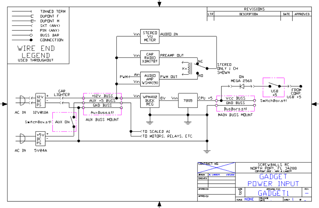
IO Device List
Too many IO's to build out one large schematic. Use the following table to map devices. Individual sections will be drawn and added as they are finalized.
IO Device List
KY-023 Joystick
Joystick Schematic & Connections
KY-023 Joystick

Gadget Project - Power Supplies
Shows power section including main +12 and +5 development as well as aux +5 and related items.
Gadget Project - Power Supplies
LCD2004 I2C Address Jumpers
Modified item drawing showing address jumpers and cable with mounting for LCD2004 display with I2C daughter card.
LCD2004 I2C Address Jumpers
Quad Relay Jumpering
Modified item drawing showing auxiliary power connection and mounting kit for installation
Quad Relay Jumpering

IO Map
All IO's and their assignments. Device list and IO map together define MEGA 2560 connections.
IO Map
IR Remote Buttons
Button assignments to IR remote control mapping button ID's to BTN_xx definitions in the code. Drives master SWITCH / CASE statement block.
IR Remote Buttons

KY-023 Joystick
Joystick Schematic & Connections
KY-023 Joystick
IO Device List
Too many IO's to build out one large schematic. Use the following table to map devices. Individual sections will be drawn and added as they are finalized.
IO Device List
IO Map
All IO's and their assignments. Device list and IO map together define MEGA 2560 connections.
IO Map
IR Remote Buttons
Button assignments to IR remote control mapping button ID's to BTN_xx definitions in the code. Drives master SWITCH / CASE statement block.
IR Remote Buttons
Quad Relay Jumpering
Modified item drawing showing auxiliary power connection and mounting kit for installation
Quad Relay Jumpering
Documentation
3D .STL Print File - Joystick Box for Arduino Analog Joystick w/pushbutton action
The X-Y analog joystick has a push button for Z. The Arduino module has four #4 thru holes on a .80" x 1.05" grid. This box has a spherical opening that exactly fits the joystick. A cutout is provided in the side for cable egress. The four joystick mounting holes need to be tapped 4-40 prior to use. The four cover screw holes will accept a 6-32 x 1/2" screw without threading - do not over torque. The corners are rounded for comfort. For correct X-Y orientation the cable exits left.
3D .STL Print File - Joystick Box for Arduino Analog Joystick w/pushbutton action
3D .STL print file - HC-SR04 Sonar Rangefinder Rear Panel Mount
This is a panel mount for the HC-SR04 ultrasonic rangefinder module commonly found in Arduino kits. The mount has two #4 thru holes for attachment to the panel. The HC-SR04 module firmly slips into place and a drop of superglue can be used for a permanent grip if so desired. Use 90% infill for strength when printing.
3D .STL print file - HC-SR04 Sonar Rangefinder Rear Panel Mount
3D .STL print file - SDA/SCL Buss bars for 12 ga wire.
Want multiple I2C devices but don't have connections? Add a 12 ga buss bar for each signal SDA and SCL. Signal name embossed in base. Support towers are filleted for strength. Use 12 ga solid copper wire as buss bars. Strip a short length of 12-2 house wire and used bare ground as buss. Print at 90% infill for strength.
3D .STL print file - SDA/SCL Buss bars for 12 ga wire.
3D .STL print file - Traffic Light Housing for LED indicator
Decorative piece that looks like a traffic light. Slips over three LED indicator.
3D .STL print file - Traffic Light Housing for LED indicator
3D .STL print file - LED diffuser for Stepper Motor Driver
The stepper motor driver card has four VERY BRIGHT LEDs that indicate the state of the four drive lines. In this project the LEDs are visible and too bright. I printed this diffuser to tone down the LEDs without obscuring their function.
3D .STL print file - LED diffuser for Stepper Motor Driver
3D .STL print file - Box with 1/4" hole for toggle switch, screw lid
Need to mount a switch to control power to your project. Add any 1/4" dia switch in the built in hole. Use a soldering iron to melt cable entry notch to match your specific needs. Four corner posts designed to be threaded 6-32 x 1/2". Corners internally filleted for strength. Print at 90% infill for strength.
3D .STL print file - Box with 1/4" hole for toggle switch, screw lid
3D .STL print file - Connector Holder for Dupont connections
Arduino comes with lots of Dupont wires. After use, the connector retention may leave a bit to be desired, especially for long term connection reliability. To solve this problem, here is a little piece that engages the wires on either side of the connection, taking all of the strain off the connection to prevent pull-apart. Print at 90% infill for strength.
3D .STL print file - Connector Holder for Dupont connections
3D .STL print file - Vcc & Gnd buss bars for 12 ga wire.
Wiring lots of devices to Arduino is often difficult because there never seem to be enough power and ground connections. The pin boards just don't hold well enough for reliable module powering. Solve the lack of power and ground pins by adding 12 ga solid copper wire buss bars. Strip a few inches of 12-2 wire and use the ground wire for the busses. Solder your individual sensor wires to the busses for reliable power connections. Power with any +5V or +3.3V power source. Two #6 mounting holes provided. Buss voltage (Vcc/Gnd) is integral to the design. Support posts are filleted for strength. Print at 90% infill for strength.
3D .STL print file - Vcc & Gnd buss bars for 12 ga wire.
ZIP with Multiple 3D .STL print files - Connector Shrouds for Dupont connections
Single Dupont connectors are difficult to install onto multi-pin connectors. Additionally, single pins don't grip well. Groups of pins, however, are easier to insert and harder to mix up as a unit. These shrouds group sets of 2, 3, 4, 5, 6, & 8 stations into one connector body. Print at 90% infill for strength. Print times 3-15 min.
ZIP with Multiple 3D .STL print files - Connector Shrouds for Dupont connections
3D .STL print file - ULN2003 Stepper Motor Driver Board Mount for 28BYJ-48
Mount your stepper driver card with this simple 3D print., Mount has two holes for card and two location posts. Mounts to panel with to #6 thru holes. Print at 90% infill for strength.
3D .STL print file - ULN2003 Stepper Motor Driver Board Mount for 28BYJ-48
3D .STL print file - HC-SR04 Sonar Rangefinder Rear Panel Mount
This is a panel mount for the HC-SR04 ultrasonic rangefinder module commonly found in Arduino kits. The mount has two #4 thru holes for attachment to the panel. The HC-SR04 module firmly slips into place and a drop of superglue can be used for a permanent grip if so desired. Use 90% infill for strength when printing.
3D .STL print file - HC-SR04 Sonar Rangefinder Rear Panel Mount
3D .STL print file - Connector Holder for Dupont connections
Arduino comes with lots of Dupont wires. After use, the connector retention may leave a bit to be desired, especially for long term connection reliability. To solve this problem, here is a little piece that engages the wires on either side of the connection, taking all of the strain off the connection to prevent pull-apart. Print at 90% infill for strength.
3D .STL print file - Connector Holder for Dupont connections
3D .STL print file - Box with 1/4" hole for toggle switch, screw lid
Need to mount a switch to control power to your project. Add any 1/4" dia switch in the built in hole. Use a soldering iron to melt cable entry notch to match your specific needs. Four corner posts designed to be threaded 6-32 x 1/2". Corners internally filleted for strength. Print at 90% infill for strength.
3D .STL print file - Box with 1/4" hole for toggle switch, screw lid
3D .STL print file - SDA/SCL Buss bars for 12 ga wire.
Want multiple I2C devices but don't have connections? Add a 12 ga buss bar for each signal SDA and SCL. Signal name embossed in base. Support towers are filleted for strength. Use 12 ga solid copper wire as buss bars. Strip a short length of 12-2 house wire and used bare ground as buss. Print at 90% infill for strength.
3D .STL print file - SDA/SCL Buss bars for 12 ga wire.
3D .STL print file - LED diffuser for Stepper Motor Driver
The stepper motor driver card has four VERY BRIGHT LEDs that indicate the state of the four drive lines. In this project the LEDs are visible and too bright. I printed this diffuser to tone down the LEDs without obscuring their function.
3D .STL print file - LED diffuser for Stepper Motor Driver
3D .STL Print File - Joystick Box for Arduino Analog Joystick w/pushbutton action
The X-Y analog joystick has a push button for Z. The Arduino module has four #4 thru holes on a .80" x 1.05" grid. This box has a spherical opening that exactly fits the joystick. A cutout is provided in the side for cable egress. The four joystick mounting holes need to be tapped 4-40 prior to use. The four cover screw holes will accept a 6-32 x 1/2" screw without threading - do not over torque. The corners are rounded for comfort. For correct X-Y orientation the cable exits left.
3D .STL Print File - Joystick Box for Arduino Analog Joystick w/pushbutton action
3D .STL print file - Mounting base for Arduino Mega 2560
Panel mount for Arduino Uno and Mega 2650. Mount engages all six mounting points. Five with meltable alignment posts and one ready to be tapped 4-40 for a retention screw. Wide panel mounting tabs extend past screw shield for easy mounting without disassembly. Four side tabs with #6 thru holes for panel mounting. Design is filleted for strength. Height is 1/4" to bottom of Uno/Mega. Suggest #4 fiber washer under screw head to prevent damage to Uno/Mega. 90% infill needed for strength. 4.12m of 1.75mm PLA @ 210C & 35mm/s, .4mm nozzle, ~1 hr print time, ~90mm x 100mm x 11mm
3D .STL print file - Mounting base for Arduino Mega 2560
3D .STL print file - LCD2004 Real Panel Mount 3D print file
Rear panel mount for LCD2004 type displays. Provides four #6 mounting holes to panel. Two 4-40 tappable studs for LCD attachments. Allows I2C four wire interface card.
3D .STL print file - LCD2004 Real Panel Mount 3D print file
3D .STL print file - Traffic Light Housing for LED indicator
Decorative piece that looks like a traffic light. Slips over three LED indicator.
3D .STL print file - Traffic Light Housing for LED indicator
3D .STL print file - 5/16" potentiometer 8-way chassis mount
This file prints a mounting bracket for a standard 5/16" diameter mini potentiometer with anti-rotation tab. The pot can be mounted on either side in any of four orientations allowing complete flexibility in mounting. The base of the bracket has two #6 thru holes for mounting. The base and bracket are filleted for strength. Print at 90% infill for strength.
3D .STL print file - 5/16" potentiometer 8-way chassis mount
3D .STL print file - ULN2003 Stepper Motor Driver Board Mount for 28BYJ-48
Mount your stepper driver card with this simple 3D print., Mount has two holes for card and two location posts. Mounts to panel with to #6 thru holes. Print at 90% infill for strength.
3D .STL print file - ULN2003 Stepper Motor Driver Board Mount for 28BYJ-48
ZIP with Multiple 3D .STL print files - Connector Shrouds for Dupont connections
Single Dupont connectors are difficult to install onto multi-pin connectors. Additionally, single pins don't grip well. Groups of pins, however, are easier to insert and harder to mix up as a unit. These shrouds group sets of 2, 3, 4, 5, 6, & 8 stations into one connector body. Print at 90% infill for strength. Print times 3-15 min.
ZIP with Multiple 3D .STL print files - Connector Shrouds for Dupont connections
3D .STL print file - Mounting base for Arduino Mega 2560
Panel mount for Arduino Uno and Mega 2650. Mount engages all six mounting points. Five with meltable alignment posts and one ready to be tapped 4-40 for a retention screw. Wide panel mounting tabs extend past screw shield for easy mounting without disassembly. Four side tabs with #6 thru holes for panel mounting. Design is filleted for strength. Height is 1/4" to bottom of Uno/Mega. Suggest #4 fiber washer under screw head to prevent damage to Uno/Mega. 90% infill needed for strength. 4.12m of 1.75mm PLA @ 210C & 35mm/s, .4mm nozzle, ~1 hr print time, ~90mm x 100mm x 11mm
3D .STL print file - Mounting base for Arduino Mega 2560
3D .STL print file - LCD2004 Real Panel Mount 3D print file
Rear panel mount for LCD2004 type displays. Provides four #6 mounting holes to panel. Two 4-40 tappable studs for LCD attachments. Allows I2C four wire interface card.
3D .STL print file - LCD2004 Real Panel Mount 3D print file
3D .STL print file - Vcc & Gnd buss bars for 12 ga wire.
Wiring lots of devices to Arduino is often difficult because there never seem to be enough power and ground connections. The pin boards just don't hold well enough for reliable module powering. Solve the lack of power and ground pins by adding 12 ga solid copper wire buss bars. Strip a few inches of 12-2 wire and use the ground wire for the busses. Solder your individual sensor wires to the busses for reliable power connections. Power with any +5V or +3.3V power source. Two #6 mounting holes provided. Buss voltage (Vcc/Gnd) is integral to the design. Support posts are filleted for strength. Print at 90% infill for strength.
3D .STL print file - Vcc & Gnd buss bars for 12 ga wire.
Comments
Only logged in users can leave comments