Remote-controlled Road Rager!
This is a good starter project for beginners with Arduino, as you learn about the fundamentals of Arduino projects besides coding.
Devices & Components
Arduino Uno Rev3
IR receiver (generic)
Power Supply Module
Male/Male Jumper Wires
9V battery (generic)
Male/Female Jumper Wires
Through Hole Resistor, 200 ohm
Breadboard (generic)
LED (generic)
Dual H-Bridge motor drivers L293D
9V Battery Clip
Project description
Code
untitled
c_cpp
1#include "IRremote.h"
2
3int receiver = 9; // Signal Pin of IR receiver  to Arduino Digital Pin 11
4#define led 7 // Power LED
5
6#define m1_pwm 3
7#define  m1_A 4
8#define m1_B 5
9
10#define m2_pwm 11
11#define m2_A 12
12#define  m2_B 13
13
14int power = 0; // controls except for toggling power can only be  used when "on" (power = 1)
15
16/*-----( Declare objects )-----*/
17IRrecv  irrecv(receiver);     // create instance of 'irrecv'
18decode_results results;      // create instance of 'decode_results'
19
20/*-----( Function )-----*/
21void  translateIR() // takes action based on IR code received
22
23// describing Remote  IR codes
24
25{
26
27  switch(results.value)
28
29  {
30  case 0xFFA25D:
31  Serial.println("POWER");
32  power += 1;
33  power = power % 2;
34  Serial.println(power);
35  break;
36
37  case 0xFFE21D:
38  Serial.println("FUNC/STOP");
39  Serial.println("f1");
40  break;
41
42  case 0xFF629D:
43  Serial.println("VOL+");
44  digitalWrite(m1_A,  HIGH);
45  digitalWrite(m1_B, LOW);
46  digitalWrite(m2_A, HIGH);
47  digitalWrite(m2_B,  LOW);
48  digitalWrite(m1_pwm, HIGH);
49  digitalWrite(m2_pwm, HIGH);
50  break;
51
52  case 0xFF22DD:
53  Serial.println("FAST BACK");
54  digitalWrite(m2_A,  LOW);
55  digitalWrite(m2_B, HIGH);
56  digitalWrite(m1_A, HIGH);
57  digitalWrite(m1_B,  LOW);
58  digitalWrite(m1_pwm, HIGH);
59  digitalWrite(m2_pwm, LOW);
60  break;
61
62  case 0xFF02FD:
63  Serial.println("PAUSE");
64  digitalWrite(m1_pwm,  LOW);
65  digitalWrite(m2_pwm, LOW);
66  break;
67
68  case 0xFFC23D:
69  Serial.println("FAST FORWARD");
70  digitalWrite(m2_A, HIGH);
71  digitalWrite(m2_B,  LOW);
72  digitalWrite(m1_A, LOW);
73  digitalWrite(m1_B, HIGH);
74  digitalWrite(m2_pwm,  HIGH);
75  digitalWrite(m1_pwm, LOW);
76  break;
77
78  case 0xFFA857:
79  Serial.println("VOL-");
80  digitalWrite(m1_A, LOW);
81  digitalWrite(m1_B,  HIGH);
82  digitalWrite(m2_A, LOW);
83  digitalWrite(m2_B, HIGH);
84  digitalWrite(m1_pwm,  HIGH);
85  digitalWrite(m2_pwm, HIGH);
86  break;
87
88  case 0xFFFFFFFF:  Serial.println(" REPEAT"); break;
89
90  default:
91    Serial.println("  other button   ");
92
93  }// End Case
94
95  delay(500); // Do not get immediate  repeat
96
97
98} //END translateIR
99void setup()   /*----( SETUP: RUNS ONCE  )----*/
100{
101  pinMode(m1_pwm,OUTPUT);
102  pinMode(m1_A,OUTPUT);
103  pinMode(m1_B,OUTPUT);
104  pinMode(m2_pwm,OUTPUT);
105  pinMode(m2_A,OUTPUT);
106  pinMode(m2_B,OUTPUT);
107  Serial.begin(9600);
108  Serial.println("IR Receiver Button Decode");
109  irrecv.enableIRIn();  // Start the receiver
110
111}/*--(end setup )---*/
112
113
114void loop()   /*----(  LOOP: RUNS CONSTANTLY )----*/
115{
116  if (power == 1) {
117    digitalWrite(led,  HIGH);
118    if (irrecv.decode(&results)) // have we received an IR signal?
119    {
120      translateIR();
121      irrecv.resume(); // receive the next value
122    }
123  }
124  if (power == 0) {
125    digitalWrite(led, LOW);
126    digitalWrite(m1_pwm,  LOW);
127    digitalWrite(m2_pwm, LOW);
128    if (irrecv.decode(&results)) // have  we received an IR signal?
129    {
130      switch(results.value)
131      {
132      case 0xFFA25D:
133      Serial.println("POWER");
134      power += 1;
135      power = power % 2;
136      Serial.println(power);
137      break;
138      }
139      irrecv.resume(); // receive the next value
140    }
141  }
142}/* --(end main  loop )-- */
IRremote.h (Part of lR Reciever Library)
c_cpp
1/*
2 * IRremote
3 * Version 0.1 July, 2009
4 * Copyright 2009 Ken  Shirriff
5 * For details, see http://arcfn.com/2009/08/multi-protocol-infrared-remote-library.htm  http://arcfn.com
6 * Edited by Mitra to add new controller SANYO
7 *
8 * Interrupt  code based on NECIRrcv by Joe Knapp
9 * http://www.arduino.cc/cgi-bin/yabb2/YaBB.pl?num=1210243556
10  * Also influenced by http://zovirl.com/2008/11/12/building-a-universal-remote-with-an-arduino/
11  *
12 * JVC and Panasonic protocol added by Kristian Lauszus (Thanks to zenwheel  and other people at the original blog post)
13* LG added by Darryl Smith (based  on the JVC protocol)
14 */
15
16#ifndef IRremote_h
17#define IRremote_h
18
19//  The following are compile-time library options.
20// If you change them, recompile  the library.
21// If DEBUG is defined, a lot of debugging output will be printed  during decoding.
22// TEST must be defined for the IRtest unittests to work.  It  will make some
23// methods virtual, which will be slightly slower, which is why  it is optional.
24// #define DEBUG
25// #define TEST
26
27// Results returned  from the decoder
28class decode_results {
29public:
30  int decode_type; // NEC,  SONY, RC5, UNKNOWN
31  union { // This is used for decoding Panasonic and Sharp  data
32    unsigned int panasonicAddress;
33    unsigned int sharpAddress;
34  };
35  unsigned long value; // Decoded value
36  int bits; // Number of bits  in decoded value
37  volatile unsigned int *rawbuf; // Raw intervals in .5 us ticks
38  int rawlen; // Number of records in rawbuf.
39};
40
41// Values for decode_type
42#define  NEC 1
43#define SONY 2
44#define RC5 3
45#define RC6 4
46#define DISH 5
47#define  SHARP 6
48#define PANASONIC 7
49#define JVC 8
50#define SANYO 9
51#define MITSUBISHI  10
52#define SAMSUNG 11
53#define LG 12
54#define UNKNOWN -1
55
56// Decoded  value for NEC when a repeat code is received
57#define REPEAT 0xffffffff
58
59//  main class for receiving IR
60class IRrecv
61{
62public:
63  IRrecv(int recvpin);
64  void blink13(int blinkflag);
65  int decode(decode_results *results);
66  void  enableIRIn();
67  void resume();
68private:
69  // These are called by decode
70  int getRClevel(decode_results *results, int *offset, int *used, int t1);
71  long  decodeNEC(decode_results *results);
72  long decodeSony(decode_results *results);
73  long decodeSanyo(decode_results *results);
74  long decodeMitsubishi(decode_results  *results);
75  long decodeRC5(decode_results *results);
76  long decodeRC6(decode_results  *results);
77  long decodePanasonic(decode_results *results);
78  long decodeLG(decode_results  *results);
79  long decodeJVC(decode_results *results);
80  long decodeSAMSUNG(decode_results  *results);
81  long decodeHash(decode_results *results);
82  int compare(unsigned  int oldval, unsigned int newval);
83
84}
85;
86
87// Only used for testing;  can remove virtual for shorter code
88#ifdef TEST
89#define VIRTUAL virtual
90#else
91#define  VIRTUAL
92#endif
93
94class IRsend
95{
96public:
97  IRsend() {}
98  void  sendNEC(unsigned long data, int nbits);
99  void sendSony(unsigned long data, int  nbits);
100  // Neither Sanyo nor Mitsubishi send is implemented yet
101  //  void  sendSanyo(unsigned long data, int nbits);
102  //  void sendMitsubishi(unsigned  long data, int nbits);
103  void sendRaw(unsigned int buf[], int len, int hz);
104  void sendRC5(unsigned long data, int nbits);
105  void sendRC6(unsigned long data,  int nbits);
106  void sendDISH(unsigned long data, int nbits);
107  void sendSharp(unsigned  int address, unsigned int command);
108  void sendSharpRaw(unsigned long data, int  nbits);
109  void sendPanasonic(unsigned int address, unsigned long data);
110  void  sendJVC(unsigned long data, int nbits, int repeat); // *Note instead of sending  the REPEAT constant if you want the JVC repeat signal sent, send the original code  value and change the repeat argument from 0 to 1. JVC protocol repeats by skipping  the header NOT by sending a separate code value like NEC does.
111  // private:
112  void sendSAMSUNG(unsigned long data, int nbits);
113  void enableIROut(int khz);
114  VIRTUAL void mark(int usec);
115  VIRTUAL void space(int usec);
116}
117;
118
119//  Some useful constants
120
121#define USECPERTICK 50  // microseconds per clock interrupt  tick
122#define RAWBUF 100 // Length of raw duration buffer
123
124// Marks tend  to be 100us too long, and spaces 100us too short
125// when received due to sensor  lag.
126#define MARK_EXCESS 100
127
128#endif
129
RC Car - Code
c_cpp
This code allows the remote control to make the motors do a certain action depending on what button is pressed, using a switch statement that gets executed in an infinite loop.
1#include "IRremote.h"
2
3int receiver = 9; // Signal Pin of IR receiver  to Arduino Digital Pin 11
4#define led 7 // Power LED
5
6#define m1_pwm 3
7#define  m1_A 4
8#define m1_B 5
9
10#define m2_pwm 11
11#define m2_A 12
12#define  m2_B 13
13
14int power = 0; // controls except for toggling power can only be  used when "on" (power = 1)
15
16/*-----( Declare objects )-----*/
17IRrecv  irrecv(receiver);     // create instance of 'irrecv'
18decode_results results;      // create instance of 'decode_results'
19
20/*-----( Function )-----*/
21void  translateIR() // takes action based on IR code received
22
23// describing Remote  IR codes
24
25{
26
27  switch(results.value)
28
29  {
30  case 0xFFA25D:  // Power
31  Serial.println("POWER");
32  power += 1;
33  power = power % 2;
34  Serial.println(power);
35  break;
36
37  case 0xFFE21D:
38  Serial.println("FUNC/STOP");
39  Serial.println("f1");
40  break;
41
42  case 0xFF629D: // Forward
43  Serial.println("VOL+");
44  digitalWrite(m1_A, HIGH);
45  digitalWrite(m1_B,  LOW);
46  digitalWrite(m2_A, HIGH);
47  digitalWrite(m2_B, LOW);
48  digitalWrite(m1_pwm,  HIGH);
49  digitalWrite(m2_pwm, HIGH);
50  break;
51
52  case 0xFF22DD: //  Turn Left
53  Serial.println("FAST BACK");
54  digitalWrite(m2_A, LOW);
55  digitalWrite(m2_B, HIGH);
56  digitalWrite(m1_A, HIGH);
57  digitalWrite(m1_B,  LOW);
58  digitalWrite(m1_pwm, HIGH);
59  digitalWrite(m2_pwm, LOW);
60  break;
61
62  case 0xFF02FD: // Stop/Pause
63  Serial.println("PAUSE");
64  digitalWrite(m1_pwm,  LOW);
65  digitalWrite(m2_pwm, LOW);
66  break;
67
68  case 0xFFC23D: //  Turn Right
69  Serial.println("FAST FORWARD");
70  digitalWrite(m2_A, HIGH);
71  digitalWrite(m2_B, LOW);
72  digitalWrite(m1_A, LOW);
73  digitalWrite(m1_B,  HIGH);
74  digitalWrite(m2_pwm, HIGH);
75  digitalWrite(m1_pwm, LOW);
76  break;
77
78  case 0xFFA857: // Baackward
79  Serial.println("VOL-");
80  digitalWrite(m1_A,  LOW);
81  digitalWrite(m1_B, HIGH);
82  digitalWrite(m2_A, LOW);
83  digitalWrite(m2_B,  HIGH);
84  digitalWrite(m1_pwm, HIGH);
85  digitalWrite(m2_pwm, HIGH);
86  break;
87
88  case 0xFFFFFFFF: Serial.println(" REPEAT"); break;
89
90  default:
91    Serial.println(" other button   ");
92
93  }// End Case
94
95  delay(500); // Do not get immediate repeat
96
97
98} //END translateIR
99void  setup()   /*----( SETUP: RUNS ONCE )----*/
100{
101  pinMode(m1_pwm,OUTPUT);
102  pinMode(m1_A,OUTPUT);
103  pinMode(m1_B,OUTPUT);
104  pinMode(m2_pwm,OUTPUT);
105  pinMode(m2_A,OUTPUT);
106  pinMode(m2_B,OUTPUT);
107  Serial.begin(9600);
108  Serial.println("IR Receiver Button Decode");
109  irrecv.enableIRIn(); // Start  the receiver
110
111}/*--(end setup )---*/
112
113
114void loop()   /*----( LOOP:  RUNS CONSTANTLY )----*/
115{
116  if (power == 1) {
117    digitalWrite(led, HIGH);
118    if (irrecv.decode(&results)) // have we received an IR signal?
119    {
120      translateIR();
121      irrecv.resume(); // receive the next value
122    }
123  }
124  if (power == 0) {
125    digitalWrite(led, LOW);
126    digitalWrite(m1_pwm,  LOW);
127    digitalWrite(m2_pwm, LOW);
128    if (irrecv.decode(&results)) // have  we received an IR signal?
129    {
130      switch(results.value)
131      {
132      case 0xFFA25D:
133      Serial.println("POWER");
134      power += 1;
135      power = power % 2;
136      Serial.println(power);
137      break;
138      }
139      irrecv.resume(); // receive the next value
140    }
141  }
142}/* --(end main  loop )-- */
143
IRremote.cpp (Part of lR Reciever Library)
c_cpp
1/*
2 * IRremote
3 * Version 0.11 August, 2009
4 * Copyright 2009  Ken Shirriff
5 * For details, see http://arcfn.com/2009/08/multi-protocol-infrared-remote-library.html
6  *
7 * Modified by Paul Stoffregen <paul@pjrc.com> to support other boards and  timers
8 * Modified  by Mitra Ardron <mitra@mitra.biz>
9 * Added Sanyo and  Mitsubishi controllers
10 * Modified Sony to spot the repeat codes that some Sony's  send
11 *
12 * Interrupt code based on NECIRrcv by Joe Knapp
13 * http://www.arduino.cc/cgi-bin/yabb2/YaBB.pl?num=1210243556
14  * Also influenced by http://zovirl.com/2008/11/12/building-a-universal-remote-with-an-arduino/
15  *
16 * JVC and Panasonic protocol added by Kristian Lauszus (Thanks to zenwheel  and other people at the original blog post)
17 * LG added by Darryl Smith (based  on the JVC protocol)
18 */
19
20#include "IRremote.h"
21#include "IRremoteInt.h"
22
23//  Provides ISR
24#include <avr/interrupt.h>
25
26volatile irparams_t irparams;
27
28//  These versions of MATCH, MATCH_MARK, and MATCH_SPACE are only for debugging.
29//  To use them, set DEBUG in IRremoteInt.h
30// Normally macros are used for efficiency
31#ifdef  DEBUG
32int MATCH(int measured, int desired) {
33  Serial.print("Testing: ");
34  Serial.print(TICKS_LOW(desired), DEC);
35  Serial.print(" <= ");
36  Serial.print(measured,  DEC);
37  Serial.print(" <= ");
38  Serial.println(TICKS_HIGH(desired), DEC);
39  return measured >= TICKS_LOW(desired) && measured <= TICKS_HIGH(desired);
40}
41
42int  MATCH_MARK(int measured_ticks, int desired_us) {
43  Serial.print("Testing mark  ");
44  Serial.print(measured_ticks * USECPERTICK, DEC);
45  Serial.print("  vs ");
46  Serial.print(desired_us, DEC);
47  Serial.print(": ");
48  Serial.print(TICKS_LOW(desired_us  + MARK_EXCESS), DEC);
49  Serial.print(" <= ");
50  Serial.print(measured_ticks,  DEC);
51  Serial.print(" <= ");
52  Serial.println(TICKS_HIGH(desired_us + MARK_EXCESS),  DEC);
53  return measured_ticks >= TICKS_LOW(desired_us + MARK_EXCESS) && measured_ticks  <= TICKS_HIGH(desired_us + MARK_EXCESS);
54}
55
56int MATCH_SPACE(int measured_ticks,  int desired_us) {
57  Serial.print("Testing space ");
58  Serial.print(measured_ticks  * USECPERTICK, DEC);
59  Serial.print(" vs ");
60  Serial.print(desired_us,  DEC);
61  Serial.print(": ");
62  Serial.print(TICKS_LOW(desired_us - MARK_EXCESS),  DEC);
63  Serial.print(" <= ");
64  Serial.print(measured_ticks, DEC);
65  Serial.print("  <= ");
66  Serial.println(TICKS_HIGH(desired_us - MARK_EXCESS), DEC);
67  return  measured_ticks >= TICKS_LOW(desired_us - MARK_EXCESS) && measured_ticks <= TICKS_HIGH(desired_us  - MARK_EXCESS);
68}
69#else
70int MATCH(int measured, int desired) {return measured  >= TICKS_LOW(desired) && measured <= TICKS_HIGH(desired);}
71int MATCH_MARK(int  measured_ticks, int desired_us) {return MATCH(measured_ticks, (desired_us + MARK_EXCESS));}
72int  MATCH_SPACE(int measured_ticks, int desired_us) {return MATCH(measured_ticks, (desired_us  - MARK_EXCESS));}
73// Debugging versions are in IRremote.cpp
74#endif
75
76void  IRsend::sendNEC(unsigned long data, int nbits)
77{
78  enableIROut(38);
79  mark(NEC_HDR_MARK);
80  space(NEC_HDR_SPACE);
81  for (int i = 0; i < nbits; i++) {
82    if (data &  TOPBIT) {
83      mark(NEC_BIT_MARK);
84      space(NEC_ONE_SPACE);
85    }
86    else {
87      mark(NEC_BIT_MARK);
88      space(NEC_ZERO_SPACE);
89    }
90    data <<= 1;
91  }
92  mark(NEC_BIT_MARK);
93  space(0);
94}
95
96void  IRsend::sendSony(unsigned long data, int nbits) {
97  enableIROut(40);
98  mark(SONY_HDR_MARK);
99  space(SONY_HDR_SPACE);
100  data = data << (32 - nbits);
101  for (int i = 0;  i < nbits; i++) {
102    if (data & TOPBIT) {
103      mark(SONY_ONE_MARK);
104      space(SONY_HDR_SPACE);
105    }
106    else {
107      mark(SONY_ZERO_MARK);
108      space(SONY_HDR_SPACE);
109    }
110    data <<= 1;
111  }
112}
113
114void  IRsend::sendRaw(unsigned int buf[], int len, int hz)
115{
116  enableIROut(hz);
117  for (int i = 0; i < len; i++) {
118    if (i & 1) {
119      space(buf[i]);
120    }
121    else {
122      mark(buf[i]);
123    }
124  }
125  space(0); // Just  to be sure
126}
127
128// Note: first bit must be a one (start bit)
129void IRsend::sendRC5(unsigned  long data, int nbits)
130{
131  enableIROut(36);
132  data = data << (32 - nbits);
133  mark(RC5_T1); // First start bit
134  space(RC5_T1); // Second start bit
135  mark(RC5_T1);  // Second start bit
136  for (int i = 0; i < nbits; i++) {
137    if (data & TOPBIT)  {
138      space(RC5_T1); // 1 is space, then mark
139      mark(RC5_T1);
140    }
141    else {
142      mark(RC5_T1);
143      space(RC5_T1);
144    }
145    data  <<= 1;
146  }
147  space(0); // Turn off at end
148}
149
150// Caller needs to take  care of flipping the toggle bit
151void IRsend::sendRC6(unsigned long data, int  nbits)
152{
153  enableIROut(36);
154  data = data << (32 - nbits);
155  mark(RC6_HDR_MARK);
156  space(RC6_HDR_SPACE);
157  mark(RC6_T1); // start bit
158  space(RC6_T1);
159  int t;
160  for (int i = 0; i < nbits; i++) {
161    if (i == 3) {
162      //  double-wide trailer bit
163      t = 2 * RC6_T1;
164    }
165    else {
166      t  = RC6_T1;
167    }
168    if (data & TOPBIT) {
169      mark(t);
170      space(t);
171    }
172    else {
173      space(t);
174      mark(t);
175    }
176
177    data  <<= 1;
178  }
179  space(0); // Turn off at end
180}
181void IRsend::sendPanasonic(unsigned  int address, unsigned long data) {
182    enableIROut(35);
183    mark(PANASONIC_HDR_MARK);
184    space(PANASONIC_HDR_SPACE);
185
186    for(int i=0;i<16;i++)
187    {
188        mark(PANASONIC_BIT_MARK);
189        if (address & 0x8000) {
190            space(PANASONIC_ONE_SPACE);
191        } else {
192            space(PANASONIC_ZERO_SPACE);
193        }
194        address  <<= 1;
195    }
196    for (int i=0; i < 32; i++) {
197        mark(PANASONIC_BIT_MARK);
198        if (data & TOPBIT) {
199            space(PANASONIC_ONE_SPACE);
200        }  else {
201            space(PANASONIC_ZERO_SPACE);
202        }
203        data  <<= 1;
204    }
205    mark(PANASONIC_BIT_MARK);
206    space(0);
207}
208void IRsend::sendJVC(unsigned  long data, int nbits, int repeat)
209{
210    enableIROut(38);
211    data = data  << (32 - nbits);
212    if (!repeat){
213        mark(JVC_HDR_MARK);
214        space(JVC_HDR_SPACE);
215    }
216    for (int i = 0; i < nbits; i++) {
217        if (data & TOPBIT)  {
218            mark(JVC_BIT_MARK);
219            space(JVC_ONE_SPACE);
220        }
221        else {
222            mark(JVC_BIT_MARK);
223            space(JVC_ZERO_SPACE);
224        }
225        data <<= 1;
226    }
227    mark(JVC_BIT_MARK);
228    space(0);
229}
230
231void  IRsend::sendSAMSUNG(unsigned long data, int nbits)
232{
233  enableIROut(38);
234  mark(SAMSUNG_HDR_MARK);
235  space(SAMSUNG_HDR_SPACE);
236  for (int i = 0; i  < nbits; i++) {
237    if (data & TOPBIT) {
238      mark(SAMSUNG_BIT_MARK);
239      space(SAMSUNG_ONE_SPACE);
240    }
241    else {
242      mark(SAMSUNG_BIT_MARK);
243      space(SAMSUNG_ZERO_SPACE);
244    }
245    data <<= 1;
246  }
247  mark(SAMSUNG_BIT_MARK);
248  space(0);
249}
250
251void IRsend::mark(int time) {
252  // Sends an IR mark for  the specified number of microseconds.
253  // The mark output is modulated at the  PWM frequency.
254  TIMER_ENABLE_PWM; // Enable pin 3 PWM output
255  if (time >  0) delayMicroseconds(time);
256}
257
258/* Leave pin off for time (given in microseconds)  */
259void IRsend::space(int time) {
260  // Sends an IR space for the specified  number of microseconds.
261  // A space is no output, so the PWM output is disabled.
262  TIMER_DISABLE_PWM; // Disable pin 3 PWM output
263  if (time > 0) delayMicroseconds(time);
264}
265
266void  IRsend::enableIROut(int khz) {
267  // Enables IR output.  The khz value controls  the modulation frequency in kilohertz.
268  // The IR output will be on pin 3 (OC2B).
269  // This routine is designed for 36-40KHz; if you use it for other values, it's  up to you
270  // to make sure it gives reasonable results.  (Watch out for overflow  / underflow / rounding.)
271  // TIMER2 is used in phase-correct PWM mode, with  OCR2A controlling the frequency and OCR2B
272  // controlling the duty cycle.
273  // There is no prescaling, so the output frequency is 16MHz / (2 * OCR2A)
274  // To turn the output on and off, we leave the PWM running, but connect and disconnect  the output pin.
275  // A few hours staring at the ATmega documentation and this  will all make sense.
276  // See my Secrets of Arduino PWM at http://arcfn.com/2009/07/secrets-of-arduino-pwm.html  for details.
277
278
279  // Disable the Timer2 Interrupt (which is used for receiving  IR)
280  TIMER_DISABLE_INTR; //Timer2 Overflow Interrupt
281
282  pinMode(TIMER_PWM_PIN,  OUTPUT);
283  digitalWrite(TIMER_PWM_PIN, LOW); // When not sending PWM, we want  it low
284
285  // COM2A = 00: disconnect OC2A
286  // COM2B = 00: disconnect  OC2B; to send signal set to 10: OC2B non-inverted
287  // WGM2 = 101: phase-correct  PWM with OCRA as top
288  // CS2 = 000: no prescaling
289  // The top value for  the timer.  The modulation frequency will be SYSCLOCK / 2 / OCR2A.
290  TIMER_CONFIG_KHZ(khz);
291}
292
293IRrecv::IRrecv(int  recvpin)
294{
295  irparams.recvpin = recvpin;
296  irparams.blinkflag = 0;
297}
298
299//  initialization
300void IRrecv::enableIRIn() {
301  cli();
302  // setup pulse clock  timer interrupt
303  //Prescale /8 (16M/8 = 0.5 microseconds per tick)
304  // Therefore,  the timer interval can range from 0.5 to 128 microseconds
305  // depending on the  reset value (255 to 0)
306  TIMER_CONFIG_NORMAL();
307
308  //Timer2 Overflow Interrupt  Enable
309  TIMER_ENABLE_INTR;
310
311  TIMER_RESET;
312
313  sei();  // enable  interrupts
314
315  // initialize state machine variables
316  irparams.rcvstate  = STATE_IDLE;
317  irparams.rawlen = 0;
318
319  // set pin modes
320  pinMode(irparams.recvpin,  INPUT);
321}
322
323// enable/disable blinking of pin 13 on IR processing
324void  IRrecv::blink13(int blinkflag)
325{
326  irparams.blinkflag = blinkflag;
327  if  (blinkflag)
328    pinMode(BLINKLED, OUTPUT);
329}
330
331// TIMER2 interrupt code  to collect raw data.
332// Widths of alternating SPACE, MARK are recorded in rawbuf.
333//  Recorded in ticks of 50 microseconds.
334// rawlen counts the number of entries  recorded so far.
335// First entry is the SPACE between transmissions.
336// As  soon as a SPACE gets long, ready is set, state switches to IDLE, timing of SPACE  continues.
337// As soon as first MARK arrives, gap width is recorded, ready is  cleared, and new logging starts
338ISR(TIMER_INTR_NAME)
339{
340  TIMER_RESET;
341
342  uint8_t irdata = (uint8_t)digitalRead(irparams.recvpin);
343
344  irparams.timer++;  // One more 50us tick
345  if (irparams.rawlen >= RAWBUF) {
346    // Buffer overflow
347    irparams.rcvstate = STATE_STOP;
348  }
349  switch(irparams.rcvstate) {
350  case STATE_IDLE: // In the middle of a gap
351    if (irdata == MARK) {
352      if  (irparams.timer < GAP_TICKS) {
353        // Not big enough to be a gap.
354        irparams.timer  = 0;
355      }
356      else {
357        // gap just ended, record duration and  start recording transmission
358        irparams.rawlen = 0;
359        irparams.rawbuf[irparams.rawlen++]  = irparams.timer;
360        irparams.timer = 0;
361        irparams.rcvstate =  STATE_MARK;
362      }
363    }
364    break;
365  case STATE_MARK: // timing MARK
366    if (irdata == SPACE) {   // MARK ended, record time
367      irparams.rawbuf[irparams.rawlen++]  = irparams.timer;
368      irparams.timer = 0;
369      irparams.rcvstate = STATE_SPACE;
370    }
371    break;
372  case STATE_SPACE: // timing SPACE
373    if (irdata ==  MARK) { // SPACE just ended, record it
374      irparams.rawbuf[irparams.rawlen++]  = irparams.timer;
375      irparams.timer = 0;
376      irparams.rcvstate = STATE_MARK;
377    }
378    else { // SPACE
379      if (irparams.timer > GAP_TICKS) {
380        //  big SPACE, indicates gap between codes
381        // Mark current code as ready  for processing
382        // Switch to STOP
383        // Don't reset timer; keep  counting space width
384        irparams.rcvstate = STATE_STOP;
385      }
386    }
387    break;
388  case STATE_STOP: // waiting, measuring gap
389    if (irdata  == MARK) { // reset gap timer
390      irparams.timer = 0;
391    }
392    break;
393  }
394
395  if (irparams.blinkflag) {
396    if (irdata == MARK) {
397      BLINKLED_ON();  // turn pin 13 LED on
398    }
399    else {
400      BLINKLED_OFF();  // turn  pin 13 LED off
401    }
402  }
403}
404
405void IRrecv::resume() {
406  irparams.rcvstate  = STATE_IDLE;
407  irparams.rawlen = 0;
408}
409
410
411
412// Decodes the received  IR message
413// Returns 0 if no data ready, 1 if data ready.
414// Results of decoding  are stored in results
415int IRrecv::decode(decode_results *results) {
416  results->rawbuf  = irparams.rawbuf;
417  results->rawlen = irparams.rawlen;
418  if (irparams.rcvstate  != STATE_STOP) {
419    return ERR;
420  }
421#ifdef DEBUG
422  Serial.println("Attempting  NEC decode");
423#endif
424  if (decodeNEC(results)) {
425    return DECODED;
426  }
427#ifdef DEBUG
428  Serial.println("Attempting Sony decode");
429#endif
430  if (decodeSony(results)) {
431    return DECODED;
432  }
433#ifdef DEBUG
434  Serial.println("Attempting  Sanyo decode");
435#endif
436  if (decodeSanyo(results)) {
437    return DECODED;
438  }
439#ifdef DEBUG
440  Serial.println("Attempting Mitsubishi decode");
441#endif
442  if (decodeMitsubishi(results)) {
443    return DECODED;
444  }
445#ifdef DEBUG
446  Serial.println("Attempting RC5 decode");
447#endif
448  if (decodeRC5(results))  {
449    return DECODED;
450  }
451#ifdef DEBUG
452  Serial.println("Attempting  RC6 decode");
453#endif
454  if (decodeRC6(results)) {
455    return DECODED;
456  }
457#ifdef DEBUG
458    Serial.println("Attempting Panasonic decode");
459#endif
460    if (decodePanasonic(results)) {
461        return DECODED;
462    }
463#ifdef  DEBUG
464    Serial.println("Attempting LG decode");
465#endif
466    if (decodeLG(results))  {
467        return DECODED;
468    }
469#ifdef DEBUG
470    Serial.println("Attempting  JVC decode");
471#endif
472    if (decodeJVC(results)) {
473        return DECODED;
474    }
475#ifdef DEBUG
476  Serial.println("Attempting SAMSUNG decode");
477#endif
478  if (decodeSAMSUNG(results)) {
479    return DECODED;
480  }
481  // decodeHash  returns a hash on any input.
482  // Thus, it needs to be last in the list.
483  // If you add any decodes, add them before this.
484  if (decodeHash(results))  {
485    return DECODED;
486  }
487  // Throw away and start over
488  resume();
489  return ERR;
490}
491
492// NECs have a repeat only 4 items long
493long IRrecv::decodeNEC(decode_results  *results) {
494  long data = 0;
495  int offset = 1; // Skip first space
496  //  Initial mark
497  if (!MATCH_MARK(results->rawbuf[offset], NEC_HDR_MARK)) {
498    return ERR;
499  }
500  offset++;
501  // Check for repeat
502  if (irparams.rawlen  == 4 &&
503    MATCH_SPACE(results->rawbuf[offset], NEC_RPT_SPACE) &&
504    MATCH_MARK(results->rawbuf[offset+1],  NEC_BIT_MARK)) {
505    results->bits = 0;
506    results->value = REPEAT;
507    results->decode_type  = NEC;
508    return DECODED;
509  }
510  if (irparams.rawlen < 2 * NEC_BITS + 4)  {
511    return ERR;
512  }
513  // Initial space
514  if (!MATCH_SPACE(results->rawbuf[offset],  NEC_HDR_SPACE)) {
515    return ERR;
516  }
517  offset++;
518  for (int i = 0;  i < NEC_BITS; i++) {
519    if (!MATCH_MARK(results->rawbuf[offset], NEC_BIT_MARK))  {
520      return ERR;
521    }
522    offset++;
523    if (MATCH_SPACE(results->rawbuf[offset],  NEC_ONE_SPACE)) {
524      data = (data << 1) | 1;
525    }
526    else if (MATCH_SPACE(results->rawbuf[offset],  NEC_ZERO_SPACE)) {
527      data <<= 1;
528    }
529    else {
530      return  ERR;
531    }
532    offset++;
533  }
534  // Success
535  results->bits = NEC_BITS;
536  results->value = data;
537  results->decode_type = NEC;
538  return DECODED;
539}
540
541long  IRrecv::decodeSony(decode_results *results) {
542  long data = 0;
543  if (irparams.rawlen  < 2 * SONY_BITS + 2) {
544    return ERR;
545  }
546  int offset = 0; // Dont skip  first space, check its size
547
548  // Some Sony's deliver repeats fast after first
549  // unfortunately can't spot difference from of repeat from two fast clicks
550  if (results->rawbuf[offset] < SONY_DOUBLE_SPACE_USECS) {
551    // Serial.print("IR  Gap found: ");
552    results->bits = 0;
553    results->value = REPEAT;
554    results->decode_type  = SANYO;
555    return DECODED;
556  }
557  offset++;
558
559  // Initial mark
560  if (!MATCH_MARK(results->rawbuf[offset], SONY_HDR_MARK)) {
561    return ERR;
562  }
563  offset++;
564
565  while (offset + 1 < irparams.rawlen) {
566    if (!MATCH_SPACE(results->rawbuf[offset],  SONY_HDR_SPACE)) {
567      break;
568    }
569    offset++;
570    if (MATCH_MARK(results->rawbuf[offset],  SONY_ONE_MARK)) {
571      data = (data << 1) | 1;
572    }
573    else if (MATCH_MARK(results->rawbuf[offset],  SONY_ZERO_MARK)) {
574      data <<= 1;
575    }
576    else {
577      return  ERR;
578    }
579    offset++;
580  }
581
582  // Success
583  results->bits = (offset  - 1) / 2;
584  if (results->bits < 12) {
585    results->bits = 0;
586    return  ERR;
587  }
588  results->value = data;
589  results->decode_type = SONY;
590  return  DECODED;
591}
592
593// I think this is a Sanyo decoder - serial = SA 8650B
594//  Looks like Sony except for timings, 48 chars of data and time/space different
595long  IRrecv::decodeSanyo(decode_results *results) {
596  long data = 0;
597  if (irparams.rawlen  < 2 * SANYO_BITS + 2) {
598    return ERR;
599  }
600  int offset = 0; // Skip first  space
601  // Initial space
602  /* Put this back in for debugging - note can't  use #DEBUG as if Debug on we don't see the repeat cos of the delay
603  Serial.print("IR  Gap: ");
604  Serial.println( results->rawbuf[offset]);
605  Serial.println( "test  against:");
606  Serial.println(results->rawbuf[offset]);
607  */
608  if (results->rawbuf[offset]  < SANYO_DOUBLE_SPACE_USECS) {
609    // Serial.print("IR Gap found: ");
610    results->bits  = 0;
611    results->value = REPEAT;
612    results->decode_type = SANYO;
613    return  DECODED;
614  }
615  offset++;
616
617  // Initial mark
618  if (!MATCH_MARK(results->rawbuf[offset],  SANYO_HDR_MARK)) {
619    return ERR;
620  }
621  offset++;
622
623  // Skip Second  Mark
624  if (!MATCH_MARK(results->rawbuf[offset], SANYO_HDR_MARK)) {
625    return  ERR;
626  }
627  offset++;
628
629  while (offset + 1 < irparams.rawlen) {
630    if  (!MATCH_SPACE(results->rawbuf[offset], SANYO_HDR_SPACE)) {
631      break;
632    }
633    offset++;
634    if (MATCH_MARK(results->rawbuf[offset], SANYO_ONE_MARK)) {
635      data = (data << 1) | 1;
636    }
637    else if (MATCH_MARK(results->rawbuf[offset],  SANYO_ZERO_MARK)) {
638      data <<= 1;
639    }
640    else {
641      return  ERR;
642    }
643    offset++;
644  }
645
646  // Success
647  results->bits = (offset  - 1) / 2;
648  if (results->bits < 12) {
649    results->bits = 0;
650    return  ERR;
651  }
652  results->value = data;
653  results->decode_type = SANYO;
654  return  DECODED;
655}
656
657// Looks like Sony except for timings, 48 chars of data and  time/space different
658long IRrecv::decodeMitsubishi(decode_results *results) {
659  // Serial.print("?!? decoding Mitsubishi:");Serial.print(irparams.rawlen); Serial.print("  want "); Serial.println( 2 * MITSUBISHI_BITS + 2);
660  long data = 0;
661  if  (irparams.rawlen < 2 * MITSUBISHI_BITS + 2) {
662    return ERR;
663  }
664  int  offset = 0; // Skip first space
665  // Initial space
666  /* Put this back in  for debugging - note can't use #DEBUG as if Debug on we don't see the repeat cos  of the delay
667  Serial.print("IR Gap: ");
668  Serial.println( results->rawbuf[offset]);
669  Serial.println( "test against:");
670  Serial.println(results->rawbuf[offset]);
671  */
672  /* Not seeing double keys from Mitsubishi
673  if (results->rawbuf[offset]  < MITSUBISHI_DOUBLE_SPACE_USECS) {
674    // Serial.print("IR Gap found: ");
675    results->bits = 0;
676    results->value = REPEAT;
677    results->decode_type  = MITSUBISHI;
678    return DECODED;
679  }
680  */
681  offset++;
682
683  // Typical
684  // 14200 7 41 7 42 7 42 7 17 7 17 7 18 7 41 7 18 7 17 7 17 7 18 7 41 8 17 7 17  7 18 7 17 7
685
686  // Initial Space
687  if (!MATCH_MARK(results->rawbuf[offset],  MITSUBISHI_HDR_SPACE)) {
688    return ERR;
689  }
690  offset++;
691  while (offset  + 1 < irparams.rawlen) {
692    if (MATCH_MARK(results->rawbuf[offset], MITSUBISHI_ONE_MARK))  {
693      data = (data << 1) | 1;
694    }
695    else if (MATCH_MARK(results->rawbuf[offset],  MITSUBISHI_ZERO_MARK)) {
696      data <<= 1;
697    }
698    else {
699      //  Serial.println("A"); Serial.println(offset); Serial.println(results->rawbuf[offset]);
700      return ERR;
701    }
702    offset++;
703    if (!MATCH_SPACE(results->rawbuf[offset],  MITSUBISHI_HDR_SPACE)) {
704      // Serial.println("B"); Serial.println(offset);  Serial.println(results->rawbuf[offset]);
705      break;
706    }
707    offset++;
708  }
709
710  // Success
711  results->bits = (offset - 1) / 2;
712  if (results->bits  < MITSUBISHI_BITS) {
713    results->bits = 0;
714    return ERR;
715  }
716  results->value  = data;
717  results->decode_type = MITSUBISHI;
718  return DECODED;
719}
720
721
722//  Gets one undecoded level at a time from the raw buffer.
723// The RC5/6 decoding  is easier if the data is broken into time intervals.
724// E.g. if the buffer has  MARK for 2 time intervals and SPACE for 1,
725// successive calls to getRClevel  will return MARK, MARK, SPACE.
726// offset and used are updated to keep track of  the current position.
727// t1 is the time interval for a single bit in microseconds.
728//  Returns -1 for error (measured time interval is not a multiple of t1).
729int IRrecv::getRClevel(decode_results  *results, int *offset, int *used, int t1) {
730  if (*offset >= results->rawlen)  {
731    // After end of recorded buffer, assume SPACE.
732    return SPACE;
733  }
734  int width = results->rawbuf[*offset];
735  int val = ((*offset) % 2) ?  MARK : SPACE;
736  int correction = (val == MARK) ? MARK_EXCESS : - MARK_EXCESS;
737
738  int avail;
739  if (MATCH(width, t1 + correction)) {
740    avail = 1;
741  }
742  else if (MATCH(width, 2*t1 + correction)) {
743    avail = 2;
744  }
745  else if (MATCH(width, 3*t1 + correction)) {
746    avail = 3;
747  }
748  else  {
749    return -1;
750  }
751
752  (*used)++;
753  if (*used >= avail) {
754    *used  = 0;
755    (*offset)++;
756  }
757#ifdef DEBUG
758  if (val == MARK) {
759    Serial.println("MARK");
760  }
761  else {
762    Serial.println("SPACE");
763  }
764#endif
765  return  val;
766}
767
768long IRrecv::decodeRC5(decode_results *results) {
769  if (irparams.rawlen  < MIN_RC5_SAMPLES + 2) {
770    return ERR;
771  }
772  int offset = 1; // Skip  gap space
773  long data = 0;
774  int used = 0;
775  // Get start bits
776  if  (getRClevel(results, &offset, &used, RC5_T1) != MARK) return ERR;
777  if (getRClevel(results,  &offset, &used, RC5_T1) != SPACE) return ERR;
778  if (getRClevel(results, &offset,  &used, RC5_T1) != MARK) return ERR;
779  int nbits;
780  for (nbits = 0; offset  < irparams.rawlen; nbits++) {
781    int levelA = getRClevel(results, &offset, &used,  RC5_T1);
782    int levelB = getRClevel(results, &offset, &used, RC5_T1);
783    if  (levelA == SPACE && levelB == MARK) {
784      // 1 bit
785      data = (data <<  1) | 1;
786    }
787    else if (levelA == MARK && levelB == SPACE) {
788      //  zero bit
789      data <<= 1;
790    }
791    else {
792      return ERR;
793    }
794  }
795
796  // Success
797  results->bits = nbits;
798  results->value = data;
799  results->decode_type = RC5;
800  return DECODED;
801}
802
803long IRrecv::decodeRC6(decode_results  *results) {
804  if (results->rawlen < MIN_RC6_SAMPLES) {
805    return ERR;
806  }
807  int offset = 1; // Skip first space
808  // Initial mark
809  if (!MATCH_MARK(results->rawbuf[offset],  RC6_HDR_MARK)) {
810    return ERR;
811  }
812  offset++;
813  if (!MATCH_SPACE(results->rawbuf[offset],  RC6_HDR_SPACE)) {
814    return ERR;
815  }
816  offset++;
817  long data = 0;
818  int used = 0;
819  // Get start bit (1)
820  if (getRClevel(results, &offset,  &used, RC6_T1) != MARK) return ERR;
821  if (getRClevel(results, &offset, &used,  RC6_T1) != SPACE) return ERR;
822  int nbits;
823  for (nbits = 0; offset < results->rawlen;  nbits++) {
824    int levelA, levelB; // Next two levels
825    levelA = getRClevel(results,  &offset, &used, RC6_T1);
826    if (nbits == 3) {
827      // T bit is double wide;  make sure second half matches
828      if (levelA != getRClevel(results, &offset,  &used, RC6_T1)) return ERR;
829    }
830    levelB = getRClevel(results, &offset,  &used, RC6_T1);
831    if (nbits == 3) {
832      // T bit is double wide; make  sure second half matches
833      if (levelB != getRClevel(results, &offset, &used,  RC6_T1)) return ERR;
834    }
835    if (levelA == MARK && levelB == SPACE) { //  reversed compared to RC5
836      // 1 bit
837      data = (data << 1) | 1;
838    }
839    else if (levelA == SPACE && levelB == MARK) {
840      // zero bit
841      data <<= 1;
842    }
843    else {
844      return ERR; // Error
845    }
846  }
847  // Success
848  results->bits = nbits;
849  results->value = data;
850  results->decode_type = RC6;
851  return DECODED;
852}
853long IRrecv::decodePanasonic(decode_results  *results) {
854    unsigned long long data = 0;
855    int offset = 1;
856
857    if (!MATCH_MARK(results->rawbuf[offset], PANASONIC_HDR_MARK)) {
858        return  ERR;
859    }
860    offset++;
861    if (!MATCH_MARK(results->rawbuf[offset], PANASONIC_HDR_SPACE))  {
862        return ERR;
863    }
864    offset++;
865
866    // decode address
867    for (int i = 0; i < PANASONIC_BITS; i++) {
868        if (!MATCH_MARK(results->rawbuf[offset++],  PANASONIC_BIT_MARK)) {
869            return ERR;
870        }
871        if (MATCH_SPACE(results->rawbuf[offset],PANASONIC_ONE_SPACE))  {
872            data = (data << 1) | 1;
873        } else if (MATCH_SPACE(results->rawbuf[offset],PANASONIC_ZERO_SPACE))  {
874            data <<= 1;
875        } else {
876            return ERR;
877        }
878        offset++;
879    }
880    results->value = (unsigned long)data;
881    results->panasonicAddress = (unsigned int)(data >> 32);
882    results->decode_type  = PANASONIC;
883    results->bits = PANASONIC_BITS;
884    return DECODED;
885}
886
887long  IRrecv::decodeLG(decode_results *results) {
888    long data = 0;
889    int offset  = 1; // Skip first space
890
891    // Initial mark
892    if (!MATCH_MARK(results->rawbuf[offset],  LG_HDR_MARK)) {
893        return ERR;
894    }
895    offset++;
896    if (irparams.rawlen  < 2 * LG_BITS + 1 ) {
897        return ERR;
898    }
899    // Initial space
900    if (!MATCH_SPACE(results->rawbuf[offset], LG_HDR_SPACE)) {
901        return  ERR;
902    }
903    offset++;
904    for (int i = 0; i < LG_BITS; i++) {
905        if  (!MATCH_MARK(results->rawbuf[offset], LG_BIT_MARK)) {
906            return ERR;
907        }
908        offset++;
909        if (MATCH_SPACE(results->rawbuf[offset],  LG_ONE_SPACE)) {
910            data = (data << 1) | 1;
911        }
912        else  if (MATCH_SPACE(results->rawbuf[offset], LG_ZERO_SPACE)) {
913            data <<=  1;
914        }
915        else {
916            return ERR;
917        }
918        offset++;
919    }
920    //Stop bit
921    if (!MATCH_MARK(results->rawbuf[offset], LG_BIT_MARK)){
922        return ERR;
923    }
924    // Success
925    results->bits = LG_BITS;
926    results->value = data;
927    results->decode_type = LG;
928    return DECODED;
929}
930
931
932long  IRrecv::decodeJVC(decode_results *results) {
933    long data = 0;
934    int offset  = 1; // Skip first space
935    // Check for repeat
936    if (irparams.rawlen -  1 == 33 &&
937        MATCH_MARK(results->rawbuf[offset], JVC_BIT_MARK) &&
938        MATCH_MARK(results->rawbuf[irparams.rawlen-1],  JVC_BIT_MARK)) {
939        results->bits = 0;
940        results->value = REPEAT;
941        results->decode_type = JVC;
942        return DECODED;
943    }
944    //  Initial mark
945    if (!MATCH_MARK(results->rawbuf[offset], JVC_HDR_MARK)) {
946        return ERR;
947    }
948    offset++;
949    if (irparams.rawlen < 2 *  JVC_BITS + 1 ) {
950        return ERR;
951    }
952    // Initial space
953    if  (!MATCH_SPACE(results->rawbuf[offset], JVC_HDR_SPACE)) {
954        return ERR;
955    }
956    offset++;
957    for (int i = 0; i < JVC_BITS; i++) {
958        if  (!MATCH_MARK(results->rawbuf[offset], JVC_BIT_MARK)) {
959            return ERR;
960        }
961        offset++;
962        if (MATCH_SPACE(results->rawbuf[offset],  JVC_ONE_SPACE)) {
963            data = (data << 1) | 1;
964        }
965        else  if (MATCH_SPACE(results->rawbuf[offset], JVC_ZERO_SPACE)) {
966            data  <<= 1;
967        }
968        else {
969            return ERR;
970        }
971        offset++;
972    }
973    //Stop bit
974    if (!MATCH_MARK(results->rawbuf[offset],  JVC_BIT_MARK)){
975        return ERR;
976    }
977    // Success
978    results->bits  = JVC_BITS;
979    results->value = data;
980    results->decode_type = JVC;
981    return DECODED;
982}
983
984// SAMSUNGs have a repeat only 4 items long
985long  IRrecv::decodeSAMSUNG(decode_results *results) {
986  long data = 0;
987  int offset  = 1; // Skip first space
988  // Initial mark
989  if (!MATCH_MARK(results->rawbuf[offset],  SAMSUNG_HDR_MARK)) {
990    return ERR;
991  }
992  offset++;
993  // Check for  repeat
994  if (irparams.rawlen == 4 &&
995    MATCH_SPACE(results->rawbuf[offset],  SAMSUNG_RPT_SPACE) &&
996    MATCH_MARK(results->rawbuf[offset+1], SAMSUNG_BIT_MARK))  {
997    results->bits = 0;
998    results->value = REPEAT;
999    results->decode_type  = SAMSUNG;
1000    return DECODED;
1001  }
1002  if (irparams.rawlen < 2 * SAMSUNG_BITS  + 4) {
1003    return ERR;
1004  }
1005  // Initial space
1006  if (!MATCH_SPACE(results->rawbuf[offset],  SAMSUNG_HDR_SPACE)) {
1007    return ERR;
1008  }
1009  offset++;
1010  for (int i =  0; i < SAMSUNG_BITS; i++) {
1011    if (!MATCH_MARK(results->rawbuf[offset], SAMSUNG_BIT_MARK))  {
1012      return ERR;
1013    }
1014    offset++;
1015    if (MATCH_SPACE(results->rawbuf[offset],  SAMSUNG_ONE_SPACE)) {
1016      data = (data << 1) | 1;
1017    }
1018    else if  (MATCH_SPACE(results->rawbuf[offset], SAMSUNG_ZERO_SPACE)) {
1019      data <<= 1;
1020    }
1021    else {
1022      return ERR;
1023    }
1024    offset++;
1025  }
1026  //  Success
1027  results->bits = SAMSUNG_BITS;
1028  results->value = data;
1029  results->decode_type  = SAMSUNG;
1030  return DECODED;
1031}
1032
1033/* -----------------------------------------------------------------------
1034  * hashdecode - decode an arbitrary IR code.
1035 * Instead of decoding using a standard  encoding scheme
1036 * (e.g. Sony, NEC, RC5), the code is hashed to a 32-bit value.
1037  *
1038 * The algorithm: look at the sequence of MARK signals, and see if each one
1039  * is shorter (0), the same length (1), or longer (2) than the previous.
1040 * Do  the same with the SPACE signals.  Hszh the resulting sequence of 0's,
1041 * 1's,  and 2's to a 32-bit value.  This will give a unique value for each
1042 * different  code (probably), for most code systems.
1043 *
1044 * http://arcfn.com/2010/01/using-arbitrary-remotes-with-arduino.html
1045  */
1046
1047// Compare two tick values, returning 0 if newval is shorter,
1048// 1  if newval is equal, and 2 if newval is longer
1049// Use a tolerance of 20%
1050int  IRrecv::compare(unsigned int oldval, unsigned int newval) {
1051  if (newval < oldval  * .8) {
1052    return 0;
1053  }
1054  else if (oldval < newval * .8) {
1055    return  2;
1056  }
1057  else {
1058    return 1;
1059  }
1060}
1061
1062// Use FNV hash algorithm:  http://isthe.com/chongo/tech/comp/fnv/#FNV-param
1063#define FNV_PRIME_32 16777619
1064#define  FNV_BASIS_32 2166136261
1065
1066/* Converts the raw code values into a 32-bit hash  code.
1067 * Hopefully this code is unique for each button.
1068 * This isn't a "real"  decoding, just an arbitrary value.
1069 */
1070long IRrecv::decodeHash(decode_results  *results) {
1071  // Require at least 6 samples to prevent triggering on noise
1072  if (results->rawlen < 6) {
1073    return ERR;
1074  }
1075  long hash = FNV_BASIS_32;
1076  for (int i = 1; i+2 < results->rawlen; i++) {
1077    int value =  compare(results->rawbuf[i],  results->rawbuf[i+2]);
1078    // Add value into the hash
1079    hash = (hash * FNV_PRIME_32)  ^ value;
1080  }
1081  results->value = hash;
1082  results->bits = 32;
1083  results->decode_type  = UNKNOWN;
1084  return DECODED;
1085}
1086
1087/* Sharp and DISH support by Todd Treece  ( http://unionbridge.org/design/ircommand )
1088
1089The Dish send function needs  to be repeated 4 times, and the Sharp function
1090has the necessary repeat built  in because of the need to invert the signal.
1091
1092Sharp protocol documentation:
1093http://www.sbprojects.com/knowledge/ir/sharp.htm
1094
1095Here  are the LIRC files that I found that seem to match the remote codes
1096from the  oscilloscope:
1097
1098Sharp LCD TV:
1099http://lirc.sourceforge.net/remotes/sharp/GA538WJSA
1100
1101DISH  NETWORK (echostar 301):
1102http://lirc.sourceforge.net/remotes/echostar/301_501_3100_5100_58xx_59xx
1103
1104For  the DISH codes, only send the last for characters of the hex.
1105i.e. use 0x1C10  instead of 0x0000000000001C10 which is listed in the
1106linked LIRC file.
1107*/
1108
1109void  IRsend::sendSharpRaw(unsigned long data, int nbits) {
1110  enableIROut(38);
1111
1112  // Sending codes in bursts of 3 (normal, inverted, normal) makes transmission
1113  // much more reliable. That's the exact behaviour of CD-S6470 remote control.
1114  for (int n = 0; n < 3; n++) {
1115    for (int i = 1 << (nbits-1); i > 0; i>>=1)  {
1116      if (data & i) {
1117        mark(SHARP_BIT_MARK);
1118        space(SHARP_ONE_SPACE);
1119      }
1120      else {
1121        mark(SHARP_BIT_MARK);
1122        space(SHARP_ZERO_SPACE);
1123      }
1124    }
1125
1126    mark(SHARP_BIT_MARK);
1127    space(SHARP_ZERO_SPACE);
1128    delay(40);
1129
1130    data = data ^ SHARP_TOGGLE_MASK;
1131  }
1132}
1133
1134//  Sharp send compatible with data obtained through decodeSharp
1135void IRsend::sendSharp(unsigned  int address, unsigned int command) {
1136  sendSharpRaw((address << 10) | (command  << 2) | 2, 15);
1137}
1138
1139void IRsend::sendDISH(unsigned long data, int nbits)  {
1140  enableIROut(56);
1141  mark(DISH_HDR_MARK);
1142  space(DISH_HDR_SPACE);
1143  for (int i = 0; i < nbits; i++) {
1144    if (data & DISH_TOP_BIT) {
1145      mark(DISH_BIT_MARK);
1146      space(DISH_ONE_SPACE);
1147    }
1148    else {
1149      mark(DISH_BIT_MARK);
1150      space(DISH_ZERO_SPACE);
1151    }
1152    data <<= 1;
1153  }
1154}
1155
RC Car - Code
c_cpp
You need to download the IRremote library to use this code.
1#include "IRremote.h"
2
3int receiver = 9; // Signal Pin of IR receiver   to Arduino Digital Pin 11
4#define led 7 // Power LED
5
6#define m1_pwm 3
7#define   m1_A 4
8#define m1_B 5
9
10#define m2_pwm 11
11#define m2_A 12
12#define   m2_B 13
13
14int power = 0; // controls except for toggling power can only be   used when "on" (power = 1)
15
16/*-----( Declare objects )-----*/
17IRrecv   irrecv(receiver);     // create instance of 'irrecv'
18decode_results results;       // create instance of 'decode_results'
19
20/*-----( Function )-----*/
21void   translateIR() // takes action based on IR code received
22
23// describing Remote   IR codes
24
25{
26
27  switch(results.value)
28
29  {
30  case 0xFFA25D:
31  Serial.println("POWER");
32  power += 1;
33  power = power % 2;
34  Serial.println(power);
35   break;
36
37  case 0xFFE21D:
38  Serial.println("FUNC/STOP");
39  Serial.println("f1");
40   break;
41
42  case 0xFF629D:
43  Serial.println("VOL+");
44  digitalWrite(m1_A,   HIGH);
45  digitalWrite(m1_B, LOW);
46  digitalWrite(m2_A, HIGH);
47  digitalWrite(m2_B,   LOW);
48  digitalWrite(m1_pwm, HIGH);
49  digitalWrite(m2_pwm, HIGH);
50  break;
51
52  case 0xFF22DD:
53  Serial.println("FAST BACK");
54  digitalWrite(m2_A,   LOW);
55  digitalWrite(m2_B, HIGH);
56  digitalWrite(m1_A, HIGH);
57  digitalWrite(m1_B,   LOW);
58  digitalWrite(m1_pwm, HIGH);
59  digitalWrite(m2_pwm, LOW);
60  break;
61
62  case 0xFF02FD:
63  Serial.println("PAUSE");
64  digitalWrite(m1_pwm,   LOW);
65  digitalWrite(m2_pwm, LOW);
66  break;
67
68  case 0xFFC23D:
69   Serial.println("FAST FORWARD");
70  digitalWrite(m2_A, HIGH);
71  digitalWrite(m2_B,   LOW);
72  digitalWrite(m1_A, LOW);
73  digitalWrite(m1_B, HIGH);
74  digitalWrite(m2_pwm,   HIGH);
75  digitalWrite(m1_pwm, LOW);
76  break;
77
78  case 0xFFA857:
79   Serial.println("VOL-");
80  digitalWrite(m1_A, LOW);
81  digitalWrite(m1_B,   HIGH);
82  digitalWrite(m2_A, LOW);
83  digitalWrite(m2_B, HIGH);
84  digitalWrite(m1_pwm,   HIGH);
85  digitalWrite(m2_pwm, HIGH);
86  break;
87
88  case 0xFFFFFFFF:   Serial.println(" REPEAT"); break;
89
90  default:
91    Serial.println("   other button   ");
92
93  }// End Case
94
95  delay(500); // Do not get immediate   repeat
96
97
98} //END translateIR
99void setup()   /*----( SETUP: RUNS ONCE   )----*/
100{
101  pinMode(m1_pwm,OUTPUT);
102  pinMode(m1_A,OUTPUT);
103  pinMode(m1_B,OUTPUT);
104   pinMode(m2_pwm,OUTPUT);
105  pinMode(m2_A,OUTPUT);
106  pinMode(m2_B,OUTPUT);
107   Serial.begin(9600);
108  Serial.println("IR Receiver Button Decode");
109  irrecv.enableIRIn();   // Start the receiver
110
111}/*--(end setup )---*/
112
113
114void loop()   /*----(   LOOP: RUNS CONSTANTLY )----*/
115{
116  if (power == 1) {
117    digitalWrite(led,   HIGH);
118    if (irrecv.decode(&results)) // have we received an IR signal?
119     {
120      translateIR();
121      irrecv.resume(); // receive the next value
122     }
123  }
124  if (power == 0) {
125    digitalWrite(led, LOW);
126    digitalWrite(m1_pwm,   LOW);
127    digitalWrite(m2_pwm, LOW);
128    if (irrecv.decode(&results)) // have   we received an IR signal?
129    {
130      switch(results.value)
131      {
132       case 0xFFA25D:
133      Serial.println("POWER");
134      power += 1;
135       power = power % 2;
136      Serial.println(power);
137      break;
138      }
139       irrecv.resume(); // receive the next value
140    }
141  }
142}/* --(end main   loop )-- */
RC Car - Circuit Diagram
svg
This is the circuit diagram for the Arduino RC car. The microprocessor in the diagram is the L293D chip. L7 and Q7 are on the same side of the chip as the notch at one of it's edges
1<?xml version="1.0" encoding="utf-8"?>
2<!-- Generator: Circuit   Diagram, cdlibrary.dll 4.0.0.0 -->
3<!DOCTYPE svg PUBLIC "-//W3C//DTD SVG 1.1//EN"   "http://www.w3.org/Graphics/SVG/1.1/DTD/svg11.dtd">
4<svg version="1.1" width="640"   height="520" xmlns="http://www.w3.org/2000/svg">
5	<line x1="500" y1="210"   x2="600" y2="210" style="stroke:rgb(0, 0, 0);stroke-linecap:square;stroke-width:2"   />
6	<line x1="500" y1="150" x2="600" y2="150" style="stroke:rgb(0,   0, 0);stroke-linecap:square;stroke-width:2" />
7	<line x1="330" y1="210"   x2="390" y2="210" style="stroke:rgb(0, 0, 0);stroke-linecap:square;stroke-width:2"   />
8	<line x1="360" y1="200" x2="380" y2="200" style="stroke:rgb(0,   0, 0);stroke-linecap:square;stroke-width:2" />
9	<line x1="330" y1="210"   x2="330" y2="490" style="stroke:rgb(0, 0, 0);stroke-linecap:square;stroke-width:2"   />
10	<line x1="40" y1="490" x2="330" y2="490" style="stroke:rgb(0, 0,   0);stroke-linecap:square;stroke-width:2" />
11	<line x1="330" y1="150" x2="390"   y2="150" style="stroke:rgb(0, 0, 0);stroke-linecap:square;stroke-width:2" />
12	<line   x1="330" y1="20" x2="330" y2="150" style="stroke:rgb(0, 0, 0);stroke-linecap:square;stroke-width:2"   />
13	<line x1="40" y1="20" x2="330" y2="20" style="stroke:rgb(0, 0,   0);stroke-linecap:square;stroke-width:2" />
14	<line x1="600" y1="150" x2="600"   y2="160" style="stroke:rgb(0, 0, 0);stroke-linecap:square;stroke-width:2" />
15	<line   x1="600" y1="200" x2="600" y2="210" style="stroke:rgb(0, 0, 0);stroke-linecap:square;stroke-width:2"   />
16	<line x1="40" y1="200" x2="40" y2="490" style="stroke:rgb(0, 0,   0);stroke-linecap:square;stroke-width:2" />
17	<line x1="40" y1="20" x2="40"   y2="160" style="stroke:rgb(0, 0, 0);stroke-linecap:square;stroke-width:2" />
18	<line   x1="40" y1="160" x2="40" y2="167" style="stroke:rgb(0, 0, 0);stroke-linecap:square;stroke-width:2"   />
19	<line x1="40" y1="193" x2="40" y2="200" style="stroke:rgb(0, 0,   0);stroke-linecap:square;stroke-width:2" />
20	<ellipse cx="40" cy="180"   rx="12" ry="12" style="fill-opacity:0;fill:rgb(0, 0, 0);stroke:rgb(0, 0, 0);stroke-width:2"   />
21	<text x="40" y="180" style="font-family:Arial;font-size:12px;text-anchor:middle"   dominant-baseline="middle" transform="rotate(0, 40, 180)">M</text>
22	<line   x1="600" y1="160" x2="600" y2="167" style="stroke:rgb(0, 0, 0);stroke-linecap:square;stroke-width:2"   />
23	<line x1="600" y1="193" x2="600" y2="200" style="stroke:rgb(0,   0, 0);stroke-linecap:square;stroke-width:2" />
24	<ellipse cx="600" cy="180"   rx="12" ry="12" style="fill-opacity:0;fill:rgb(0, 0, 0);stroke:rgb(0, 0, 0);stroke-width:2"   />
25	<text x="600" y="180" style="font-family:Arial;font-size:12px;text-anchor:middle"   dominant-baseline="middle" transform="rotate(0, 600, 180)">M</text>
26	<line   x1="500" y1="110" x2="550" y2="110" style="stroke:rgb(0, 0, 0);stroke-linecap:square;stroke-width:2"   />
27	<line x1="550" y1="110" x2="550" y2="470" style="stroke:rgb(0,   0, 0);stroke-linecap:square;stroke-width:2" />
28	<line x1="390" y1="470"   x2="550" y2="470" style="stroke:rgb(0, 0, 0);stroke-linecap:square;stroke-width:2"   />
29	<line x1="390" y1="430" x2="390" y2="470" style="stroke:rgb(0,   0, 0);stroke-linecap:square;stroke-width:2" />
30	<line x1="370" y1="170"   x2="390" y2="170" style="stroke:rgb(0, 0, 0);stroke-linecap:square;stroke-width:2"   />
31	<line x1="370" y1="330" x2="490" y2="330" style="stroke:rgb(0,   0, 0);stroke-linecap:square;stroke-width:2" />
32	<line x1="490" y1="330"   x2="490" y2="430" style="stroke:rgb(0, 0, 0);stroke-linecap:square;stroke-width:2"   />
33	<line x1="370" y1="170" x2="370" y2="330" style="stroke:rgb(0,   0, 0);stroke-linecap:square;stroke-width:2" />
34	<line x1="360" y1="250"   x2="380" y2="250" style="stroke:rgb(0, 0, 0);stroke-linecap:square;stroke-width:2"   />
35	<line x1="360" y1="250" x2="360" y2="430" style="stroke:rgb(0,   0, 0);stroke-linecap:square;stroke-width:2" />
36	<line x1="500" y1="170"   x2="530" y2="170" style="stroke:rgb(0, 0, 0);stroke-linecap:square;stroke-width:2"   />
37	<line x1="530" y1="170" x2="530" y2="430" style="stroke:rgb(0,   0, 0);stroke-linecap:square;stroke-width:2" />
38	<line x1="360" y1="430"   x2="430" y2="430" style="stroke:rgb(0, 0, 0);stroke-linecap:square;stroke-width:2"   />
39	<line x1="450" y1="430" x2="530" y2="430" style="stroke:rgb(0,   0, 0);stroke-linecap:square;stroke-width:2" />
40	<line x1="430" y1="430"   x2="424" y2="430" style="stroke:rgb(0, 0, 0);stroke-linecap:square;stroke-width:2"   />
41	<ellipse cx="440" cy="430" rx="16" ry="16" style="fill-opacity:0;fill:rgb(0,   0, 0);stroke:rgb(0, 0, 0);stroke-width:2" />
42	<line x1="456" y1="430" x2="450"   y2="430" style="stroke:rgb(0, 0, 0);stroke-linecap:square;stroke-width:2" />
43	<path   d="M 440,430 M 430,430 L 438,430 M 434,426 L 434,434 M 444,430 L 452,430" style="fill-opacity:0;fill:rgb(0,   0, 0);stroke:rgb(0, 0, 0);stroke-linecap:square;stroke-width:2" />
44	<line x1="500"   y1="130" x2="530" y2="130" style="stroke:rgb(0, 0, 0);stroke-linecap:square;stroke-width:2"   />
45	<line x1="530" y1="50" x2="530" y2="130" style="stroke:rgb(0, 0,   0);stroke-linecap:square;stroke-width:2" />
46	<line x1="500" y1="230" x2="520"   y2="230" style="stroke:rgb(0, 0, 0);stroke-linecap:square;stroke-width:2" />
47	<line   x1="520" y1="60" x2="520" y2="230" style="stroke:rgb(0, 0, 0);stroke-linecap:square;stroke-width:2"   />
48	<line x1="500" y1="250" x2="510" y2="250" style="stroke:rgb(0,   0, 0);stroke-linecap:square;stroke-width:2" />
49	<line x1="510" y1="70"   x2="510" y2="250" style="stroke:rgb(0, 0, 0);stroke-linecap:square;stroke-width:2"   />
50	<line x1="310" y1="70" x2="510" y2="70" style="stroke:rgb(0, 0,   0);stroke-linecap:square;stroke-width:2" />
51	<line x1="300" y1="60" x2="520"   y2="60" style="stroke:rgb(0, 0, 0);stroke-linecap:square;stroke-width:2" />
52	<line   x1="290" y1="50" x2="530" y2="50" style="stroke:rgb(0, 0, 0);stroke-linecap:square;stroke-width:2"   />
53	<line x1="290" y1="50" x2="290" y2="150" style="stroke:rgb(0, 0,   0);stroke-linecap:square;stroke-width:2" />
54	<line x1="300" y1="60" x2="300"   y2="160" style="stroke:rgb(0, 0, 0);stroke-linecap:square;stroke-width:2" />
55	<line   x1="310" y1="70" x2="310" y2="170" style="stroke:rgb(0, 0, 0);stroke-linecap:square;stroke-width:2"   />
56	<line x1="110" y1="200" x2="140" y2="200" style="stroke:rgb(0,   0, 0);stroke-linecap:square;stroke-width:2" />
57	<line x1="90" y1="190"   x2="140" y2="190" style="stroke:rgb(0, 0, 0);stroke-linecap:square;stroke-width:2"   />
58	<line x1="110" y1="200" x2="110" y2="450" style="stroke:rgb(0,   0, 0);stroke-linecap:square;stroke-width:2" />
59	<line x1="90" y1="190"   x2="90" y2="470" style="stroke:rgb(0, 0, 0);stroke-linecap:square;stroke-width:2"   />
60	<line x1="90" y1="470" x2="270" y2="470" style="stroke:rgb(0, 0,   0);stroke-linecap:square;stroke-width:2" />
61	<line x1="110" y1="450" x2="250"   y2="450" style="stroke:rgb(0, 0, 0);stroke-linecap:square;stroke-width:2" />
62	<line   x1="250" y1="410" x2="250" y2="450" style="stroke:rgb(0, 0, 0);stroke-linecap:square;stroke-width:2"   />
63	<line x1="270" y1="380" x2="270" y2="470" style="stroke:rgb(0,   0, 0);stroke-linecap:square;stroke-width:2" />
64	<line x1="250" y1="380"   x2="270" y2="380" style="stroke:rgb(0, 0, 0);stroke-linecap:square;stroke-width:2"   />
65	<line x1="280" y1="140" x2="350" y2="140" style="stroke:rgb(0,   0, 0);stroke-linecap:square;stroke-width:2" />
66	<line x1="350" y1="370"   x2="350" y2="375" style="stroke:rgb(0, 0, 0);stroke-linecap:square;stroke-width:2"   />
67	<line x1="350" y1="415" x2="350" y2="420" style="stroke:rgb(0,   0, 0);stroke-linecap:square;stroke-width:2" />
68	<path d="M 350,375 L 350,377   L 343,380 L 357,386 L 343,392 L 357,398 L 343,404 L 357,410 L 350,413 L 350,415"   style="fill-opacity:0;fill:rgb(0, 0, 0);stroke:rgb(0, 0, 0);stroke-linecap:square;stroke-width:2"   />
69	<text x="336" y="395" style="font-family:Arial;font-size:11px;text-anchor:end"   dominant-baseline="middle" transform="rotate(0, 336, 395)">220 </text>
70	<line   x1="350" y1="450" x2="350" y2="470" style="stroke:rgb(0, 0, 0);stroke-linecap:square;stroke-width:2"   />
71	<line x1="300" y1="470" x2="350" y2="470" style="stroke:rgb(0,   0, 0);stroke-linecap:square;stroke-width:2" />
72	<line x1="250" y1="350"   x2="310" y2="350" style="stroke:rgb(0, 0, 0);stroke-linecap:square;stroke-width:2"   />
73	<line x1="310" y1="190" x2="310" y2="350" style="stroke:rgb(0,   0, 0);stroke-linecap:square;stroke-width:2" />
74	<line x1="300" y1="220"   x2="300" y2="470" style="stroke:rgb(0, 0, 0);stroke-linecap:square;stroke-width:2"   />
75	<line x1="350" y1="140" x2="350" y2="370" style="stroke:rgb(0,   0, 0);stroke-linecap:square;stroke-width:2" />
76	<line x1="320" y1="130"   x2="380" y2="130" style="stroke:rgb(0, 0, 0);stroke-linecap:square;stroke-width:2"   />
77	<line x1="320" y1="130" x2="320" y2="240" style="stroke:rgb(0,   0, 0);stroke-linecap:square;stroke-width:2" />
78	<line x1="290" y1="230"   x2="380" y2="230" style="stroke:rgb(0, 0, 0);stroke-linecap:square;stroke-width:2"   />
79	<line x1="290" y1="230" x2="290" y2="250" style="stroke:rgb(0,   0, 0);stroke-linecap:square;stroke-width:2" />
80	<line x1="340" y1="110"   x2="380" y2="110" style="stroke:rgb(0, 0, 0);stroke-linecap:square;stroke-width:2"   />
81	<line x1="340" y1="110" x2="340" y2="260" style="stroke:rgb(0,   0, 0);stroke-linecap:square;stroke-width:2" />
82	<line x1="350" y1="450"   x2="350" y2="420" style="stroke:rgb(0, 0, 0);stroke-linecap:square;stroke-width:2"   />
83	<path d="M 350,428 M 342,428 L 358,428 M 350,428 L 358,443 L 342,443 L   350,428" style="fill-opacity:0;fill:rgb(0, 0, 0);stroke:rgb(0, 0, 0);stroke-linecap:square;stroke-width:2"   />
84	<path d="M 350,430 M 361,432 L 369,424 M 370,423 L 368,427 L 366,425 L   370,423 L 368,427" style="fill-opacity:0;fill:rgb(0, 0, 0);stroke:rgb(0, 0, 0);stroke-linecap:square;stroke-width:2"   />
85	<path d="M 350,430 M 354,426 L 362,418 M 363,417 L 361,421 L 359,419 L   363,417 L 361,421" style="fill-opacity:0;fill:rgb(0, 0, 0);stroke:rgb(0, 0, 0);stroke-linecap:square;stroke-width:2"   />
86	<line x1="270" y1="150" x2="290" y2="150" style="stroke:rgb(0,   0, 0);stroke-linecap:square;stroke-width:2" />
87	<line x1="270" y1="140"   x2="280" y2="140" style="stroke:rgb(0, 0, 0);stroke-linecap:square;stroke-width:2"   />
88	<line x1="270" y1="160" x2="300" y2="160" style="stroke:rgb(0,   0, 0);stroke-linecap:square;stroke-width:2" />
89	<line x1="280" y1="170"   x2="290" y2="170" style="stroke:rgb(0, 0, 0);stroke-linecap:square;stroke-width:2"   />
90	<line x1="270" y1="170" x2="310" y2="170" style="stroke:rgb(0,   0, 0);stroke-linecap:square;stroke-width:2" />
91	<line x1="270" y1="190"   x2="310" y2="190" style="stroke:rgb(0, 0, 0);stroke-linecap:square;stroke-width:2"   />
92	<line x1="270" y1="220" x2="300" y2="220" style="stroke:rgb(0,   0, 0);stroke-linecap:square;stroke-width:2" />
93	<line x1="270" y1="240"   x2="320" y2="240" style="stroke:rgb(0, 0, 0);stroke-linecap:square;stroke-width:2"   />
94	<rect x="180" y="330" width="40" height="100" style="fill-opacity:0;fill:rgb(0,   0, 0);stroke:rgb(0, 0, 0);stroke-width:2" />
95	<line x1="220" y1="410" x2="250"   y2="410" style="stroke:rgb(0, 0, 0);stroke-linecap:square;stroke-width:2" />
96	<line   x1="220" y1="380" x2="250" y2="380" style="stroke:rgb(0, 0, 0);stroke-linecap:square;stroke-width:2"   />
97	<line x1="220" y1="350" x2="250" y2="350" style="stroke:rgb(0,   0, 0);stroke-linecap:square;stroke-width:2" />
98	<text x="200" y="410" style="font-family:Arial;font-size:11px;text-anchor:middle"   dominant-baseline="middle" transform="rotate(0, 200, 410)">GND</text>
99	<text   x="200" y="380" style="font-family:Arial;font-size:11px;text-anchor:middle"   dominant-baseline="middle" transform="rotate(0, 200, 380)">VCC</text>
100	<text   x="200" y="350" style="font-family:Arial;font-size:11px;text-anchor:middle"   dominant-baseline="middle" transform="rotate(0, 200, 350)">DATA</text>
101	<path   d="M 200,380 M 180,410 A 30,30 0 1 1 180,350" style="fill-opacity:0;fill:rgb(0,   0, 0);stroke:rgb(0, 0, 0);stroke-linecap:square;stroke-width:2" />
102	<path d="M   150,380 M 146,342 L 154,350 M 155,351 L 153,347 L 151,349 L 155,351 L 153,347"   style="fill-opacity:0;fill:rgb(0, 0, 0);stroke:rgb(0, 0, 0);stroke-linecap:square;stroke-width:2"   />
103	<path d="M 150,380 M 140,348 L 148,356 M 149,357 L 147,353 L 145,355 L   149,357 L 147,353" style="fill-opacity:0;fill:rgb(0, 0, 0);stroke:rgb(0, 0, 0);stroke-linecap:square;stroke-width:2"   />
104	<line x1="270" y1="250" x2="290" y2="250" style="stroke:rgb(0,   0, 0);stroke-linecap:square;stroke-width:2" />
105	<line x1="270" y1="260"   x2="340" y2="260" style="stroke:rgb(0, 0, 0);stroke-linecap:square;stroke-width:2"   />
106	<rect x="390" y="100" width="100" height="200" style="fill-opacity:0;fill:rgb(0,   0, 0);stroke:rgb(0, 0, 0);stroke-width:2" />
107	<line x1="380" y1="110" x2="390"   y2="110" style="stroke:rgb(0, 0, 0);stroke-linecap:square;stroke-width:2" />
108	<line   x1="380" y1="130" x2="390" y2="130" style="stroke:rgb(0, 0, 0);stroke-linecap:square;stroke-width:2"   />
109	<line x1="380" y1="150" x2="390" y2="150" style="stroke:rgb(0,   0, 0);stroke-linecap:square;stroke-width:2" />
110	<line x1="380" y1="170"   x2="390" y2="170" style="stroke:rgb(0, 0, 0);stroke-linecap:square;stroke-width:2"   />
111	<line x1="380" y1="190" x2="390" y2="190" style="stroke:rgb(0,   0, 0);stroke-linecap:square;stroke-width:2" />
112	<line x1="380" y1="210"   x2="390" y2="210" style="stroke:rgb(0, 0, 0);stroke-linecap:square;stroke-width:2"   />
113	<line x1="380" y1="230" x2="390" y2="230" style="stroke:rgb(0,   0, 0);stroke-linecap:square;stroke-width:2" />
114	<line x1="380" y1="250"   x2="390" y2="250" style="stroke:rgb(0, 0, 0);stroke-linecap:square;stroke-width:2"   />
115	<line x1="380" y1="270" x2="390" y2="270" style="stroke:rgb(0,   0, 0);stroke-linecap:square;stroke-width:2" />
116	<line x1="380" y1="290"   x2="390" y2="290" style="stroke:rgb(0, 0, 0);stroke-linecap:square;stroke-width:2"   />
117	<line x1="490" y1="110" x2="500" y2="110" style="stroke:rgb(0,   0, 0);stroke-linecap:square;stroke-width:2" />
118	<line x1="490" y1="130"   x2="500" y2="130" style="stroke:rgb(0, 0, 0);stroke-linecap:square;stroke-width:2"   />
119	<line x1="490" y1="150" x2="500" y2="150" style="stroke:rgb(0,   0, 0);stroke-linecap:square;stroke-width:2" />
120	<line x1="490" y1="170"   x2="500" y2="170" style="stroke:rgb(0, 0, 0);stroke-linecap:square;stroke-width:2"   />
121	<line x1="490" y1="190" x2="500" y2="190" style="stroke:rgb(0,   0, 0);stroke-linecap:square;stroke-width:2" />
122	<line x1="490" y1="210"   x2="500" y2="210" style="stroke:rgb(0, 0, 0);stroke-linecap:square;stroke-width:2"   />
123	<line x1="490" y1="230" x2="500" y2="230" style="stroke:rgb(0,   0, 0);stroke-linecap:square;stroke-width:2" />
124	<line x1="490" y1="250"   x2="500" y2="250" style="stroke:rgb(0, 0, 0);stroke-linecap:square;stroke-width:2"   />
125	<text x="394" y="110" style="font-family:Arial;font-size:12px;text-anchor:start"   dominant-baseline="middle" transform="rotate(0, 394, 110)">I<tspan baseline-shift="sub"   style="font-size:0.8em">7</tspan></text>
126	<text x="394" y="130" style="font-family:Arial;font-size:12px;text-anchor:start"   dominant-baseline="middle" transform="rotate(0, 394, 130)">I<tspan baseline-shift="sub"   style="font-size:0.8em">6</tspan></text>
127	<text x="394" y="150" style="font-family:Arial;font-size:12px;text-anchor:start"   dominant-baseline="middle" transform="rotate(0, 394, 150)">I<tspan baseline-shift="sub"   style="font-size:0.8em">5</tspan></text>
128	<text x="394" y="170" style="font-family:Arial;font-size:12px;text-anchor:start"   dominant-baseline="middle" transform="rotate(0, 394, 170)">I<tspan baseline-shift="sub"   style="font-size:0.8em">4</tspan></text>
129	<text x="394" y="190" style="font-family:Arial;font-size:12px;text-anchor:start"   dominant-baseline="middle" transform="rotate(0, 394, 190)">I<tspan baseline-shift="sub"   style="font-size:0.8em">3</tspan></text>
130	<text x="394" y="210" style="font-family:Arial;font-size:12px;text-anchor:start"   dominant-baseline="middle" transform="rotate(0, 394, 210)">I<tspan baseline-shift="sub"   style="font-size:0.8em">2</tspan></text>
131	<text x="394" y="230" style="font-family:Arial;font-size:12px;text-anchor:start"   dominant-baseline="middle" transform="rotate(0, 394, 230)">I<tspan baseline-shift="sub"   style="font-size:0.8em">1</tspan></text>
132	<text x="394" y="250" style="font-family:Arial;font-size:12px;text-anchor:start"   dominant-baseline="middle" transform="rotate(0, 394, 250)">I<tspan baseline-shift="sub"   style="font-size:0.8em">0</tspan></text>
133	<text x="394" y="270" style="font-family:Arial;font-size:12px;text-anchor:start"   dominant-baseline="middle" transform="rotate(0, 394, 270)">adc</text>
134	<text   x="394" y="290" style="font-family:Arial;font-size:12px;text-anchor:start"   dominant-baseline="middle" transform="rotate(0, 394, 290)">R</text>
135	<text   x="486" y="110" style="font-family:Arial;font-size:12px;text-anchor:end" dominant-baseline="middle"   transform="rotate(0, 486, 110)">Q<tspan baseline-shift="sub" style="font-size:0.8em">7</tspan></text>
136	<text   x="486" y="130" style="font-family:Arial;font-size:12px;text-anchor:end" dominant-baseline="middle"   transform="rotate(0, 486, 130)">Q<tspan baseline-shift="sub" style="font-size:0.8em">6</tspan></text>
137	<text   x="486" y="150" style="font-family:Arial;font-size:12px;text-anchor:end" dominant-baseline="middle"   transform="rotate(0, 486, 150)">Q<tspan baseline-shift="sub" style="font-size:0.8em">5</tspan></text>
138	<text   x="486" y="170" style="font-family:Arial;font-size:12px;text-anchor:end" dominant-baseline="middle"   transform="rotate(0, 486, 170)">Q<tspan baseline-shift="sub" style="font-size:0.8em">4</tspan></text>
139	<text   x="486" y="190" style="font-family:Arial;font-size:12px;text-anchor:end" dominant-baseline="middle"   transform="rotate(0, 486, 190)">Q<tspan baseline-shift="sub" style="font-size:0.8em">3</tspan></text>
140	<text   x="486" y="210" style="font-family:Arial;font-size:12px;text-anchor:end" dominant-baseline="middle"   transform="rotate(0, 486, 210)">Q<tspan baseline-shift="sub" style="font-size:0.8em">2</tspan></text>
141	<text   x="486" y="230" style="font-family:Arial;font-size:12px;text-anchor:end" dominant-baseline="middle"   transform="rotate(0, 486, 230)">Q<tspan baseline-shift="sub" style="font-size:0.8em">1</tspan></text>
142	<text   x="486" y="250" style="font-family:Arial;font-size:12px;text-anchor:end" dominant-baseline="middle"   transform="rotate(0, 486, 250)">Q<tspan baseline-shift="sub" style="font-size:0.8em">0</tspan></text>
143	<line   x1="394" y1="282.5" x2="402" y2="282.5" style="stroke:rgb(0, 0, 0);stroke-linecap:square;stroke-width:1"   />
144	<text x="486" y="290" style="font-family:Arial;font-size:12px;text-anchor:end"   dominant-baseline="middle" transform="rotate(0, 486, 290)">Controller</text>
145	<rect   x="145" y="105" width="120" height="195" style="fill-opacity:0;fill:rgb(0,   0, 0);stroke:rgb(0, 0, 0);stroke-width:2" />
146	<text x="181" y="135" style="font-family:Arial;font-size:11px;text-anchor:start"   dominant-baseline="middle" transform="rotate(0, 181, 135)">ARDUINO</text>
147	<text   x="188" y="145" style="font-family:Arial;font-size:11px;text-anchor:start"   dominant-baseline="middle" transform="rotate(0, 188, 145)">UNO r3</text>
148	<line   x1="140" y1="160" x2="145" y2="160" style="stroke:rgb(0, 0, 0);stroke-linecap:square;stroke-width:2"   />
149	<line x1="140" y1="170" x2="145" y2="170" style="stroke:rgb(0,   0, 0);stroke-linecap:square;stroke-width:2" />
150	<line x1="140" y1="180"   x2="145" y2="180" style="stroke:rgb(0, 0, 0);stroke-linecap:square;stroke-width:2"   />
151	<line x1="140" y1="190" x2="145" y2="190" style="stroke:rgb(0,   0, 0);stroke-linecap:square;stroke-width:2" />
152	<line x1="140" y1="200"   x2="145" y2="200" style="stroke:rgb(0, 0, 0);stroke-linecap:square;stroke-width:2"   />
153	<line x1="140" y1="210" x2="145" y2="210" style="stroke:rgb(0,   0, 0);stroke-linecap:square;stroke-width:2" />
154	<line x1="140" y1="220"   x2="145" y2="220" style="stroke:rgb(0, 0, 0);stroke-linecap:square;stroke-width:2"   />
155	<line x1="140" y1="240" x2="145" y2="240" style="stroke:rgb(0,   0, 0);stroke-linecap:square;stroke-width:2" />
156	<line x1="140" y1="250"   x2="145" y2="250" style="stroke:rgb(0, 0, 0);stroke-linecap:square;stroke-width:2"   />
157	<line x1="140" y1="260" x2="145" y2="260" style="stroke:rgb(0,   0, 0);stroke-linecap:square;stroke-width:2" />
158	<line x1="140" y1="270"   x2="145" y2="270" style="stroke:rgb(0, 0, 0);stroke-linecap:square;stroke-width:2"   />
159	<line x1="140" y1="280" x2="145" y2="280" style="stroke:rgb(0,   0, 0);stroke-linecap:square;stroke-width:2" />
160	<line x1="140" y1="290"   x2="145" y2="290" style="stroke:rgb(0, 0, 0);stroke-linecap:square;stroke-width:2"   />
161	<line x1="265" y1="130" x2="270" y2="130" style="stroke:rgb(0,   0, 0);stroke-linecap:square;stroke-width:2" />
162	<line x1="265" y1="140"   x2="270" y2="140" style="stroke:rgb(0, 0, 0);stroke-linecap:square;stroke-width:2"   />
163	<line x1="265" y1="150" x2="270" y2="150" style="stroke:rgb(0,   0, 0);stroke-linecap:square;stroke-width:2" />
164	<line x1="265" y1="160"   x2="270" y2="160" style="stroke:rgb(0, 0, 0);stroke-linecap:square;stroke-width:2"   />
165	<line x1="265" y1="170" x2="270" y2="170" style="stroke:rgb(0,   0, 0);stroke-linecap:square;stroke-width:2" />
166	<line x1="265" y1="180"   x2="270" y2="180" style="stroke:rgb(0, 0, 0);stroke-linecap:square;stroke-width:2"   />
167	<line x1="265" y1="190" x2="270" y2="190" style="stroke:rgb(0,   0, 0);stroke-linecap:square;stroke-width:2" />
168	<line x1="265" y1="200"   x2="270" y2="200" style="stroke:rgb(0, 0, 0);stroke-linecap:square;stroke-width:2"   />
169	<line x1="265" y1="220" x2="270" y2="220" style="stroke:rgb(0,   0, 0);stroke-linecap:square;stroke-width:2" />
170	<line x1="265" y1="230"   x2="270" y2="230" style="stroke:rgb(0, 0, 0);stroke-linecap:square;stroke-width:2"   />
171	<line x1="265" y1="240" x2="270" y2="240" style="stroke:rgb(0,   0, 0);stroke-linecap:square;stroke-width:2" />
172	<line x1="265" y1="250"   x2="270" y2="250" style="stroke:rgb(0, 0, 0);stroke-linecap:square;stroke-width:2"   />
173	<line x1="265" y1="260" x2="270" y2="260" style="stroke:rgb(0,   0, 0);stroke-linecap:square;stroke-width:2" />
174	<line x1="265" y1="270"   x2="270" y2="270" style="stroke:rgb(0, 0, 0);stroke-linecap:square;stroke-width:2"   />
175	<line x1="265" y1="280" x2="270" y2="280" style="stroke:rgb(0,   0, 0);stroke-linecap:square;stroke-width:2" />
176	<line x1="265" y1="290"   x2="270" y2="290" style="stroke:rgb(0, 0, 0);stroke-linecap:square;stroke-width:2"   />
177	<text x="149" y="160" style="font-family:Arial;font-size:11px;text-anchor:start"   dominant-baseline="middle" transform="rotate(0, 149, 160)">IOREF</text>
178	<text   x="149" y="170" style="font-family:Arial;font-size:11px;text-anchor:start"   dominant-baseline="middle" transform="rotate(0, 149, 170)">RESET</text>
179	<text   x="149" y="180" style="font-family:Arial;font-size:11px;text-anchor:start"   dominant-baseline="middle" transform="rotate(0, 149, 180)">3.3V</text>
180	<text   x="149" y="190" style="font-family:Arial;font-size:11px;text-anchor:start"   dominant-baseline="middle" transform="rotate(0, 149, 190)">5V</text>
181	<text   x="149" y="200" style="font-family:Arial;font-size:11px;text-anchor:start"   dominant-baseline="middle" transform="rotate(0, 149, 200)">GND</text>
182	<text   x="149" y="210" style="font-family:Arial;font-size:11px;text-anchor:start"   dominant-baseline="middle" transform="rotate(0, 149, 210)">GND</text>
183	<text   x="149" y="220" style="font-family:Arial;font-size:11px;text-anchor:start"   dominant-baseline="middle" transform="rotate(0, 149, 220)">Vin</text>
184	<text   x="149" y="240" style="font-family:Arial;font-size:11px;text-anchor:start"   dominant-baseline="middle" transform="rotate(0, 149, 240)">A0</text>
185	<text   x="149" y="250" style="font-family:Arial;font-size:11px;text-anchor:start"   dominant-baseline="middle" transform="rotate(0, 149, 250)">A1</text>
186	<text   x="149" y="260" style="font-family:Arial;font-size:11px;text-anchor:start"   dominant-baseline="middle" transform="rotate(0, 149, 260)">A2</text>
187	<text   x="149" y="270" style="font-family:Arial;font-size:11px;text-anchor:start"   dominant-baseline="middle" transform="rotate(0, 149, 270)">A3</text>
188	<text   x="149" y="280" style="font-family:Arial;font-size:11px;text-anchor:start"   dominant-baseline="middle" transform="rotate(0, 149, 280)">A4</text>
189	<text   x="149" y="290" style="font-family:Arial;font-size:11px;text-anchor:start"   dominant-baseline="middle" transform="rotate(0, 149, 290)">A5</text>
190	<text   x="261" y="130" style="font-family:Arial;font-size:11px;text-anchor:end" dominant-baseline="middle"   transform="rotate(0, 261, 130)">AREF</text>
191	<text x="261" y="140" style="font-family:Arial;font-size:11px;text-anchor:end"   dominant-baseline="middle" transform="rotate(0, 261, 140)">GND</text>
192	<text   x="261" y="150" style="font-family:Arial;font-size:11px;text-anchor:end" dominant-baseline="middle"   transform="rotate(0, 261, 150)">D13</text>
193	<text x="261" y="160" style="font-family:Arial;font-size:11px;text-anchor:end"   dominant-baseline="middle" transform="rotate(0, 261, 160)">D12</text>
194	<text   x="261" y="170" style="font-family:Arial;font-size:11px;text-anchor:end" dominant-baseline="middle"   transform="rotate(0, 261, 170)">PWM D11</text>
195	<text x="261" y="180"   style="font-family:Arial;font-size:11px;text-anchor:end" dominant-baseline="middle"   transform="rotate(0, 261, 180)">PWM D10</text>
196	<text x="261" y="190"   style="font-family:Arial;font-size:11px;text-anchor:end" dominant-baseline="middle"   transform="rotate(0, 261, 190)">PWM   D9</text>
197	<text x="261" y="200"   style="font-family:Arial;font-size:11px;text-anchor:end" dominant-baseline="middle"   transform="rotate(0, 261, 200)">D8</text>
198	<text x="261" y="220" style="font-family:Arial;font-size:11px;text-anchor:end"   dominant-baseline="middle" transform="rotate(0, 261, 220)">D7</text>
199	<text   x="261" y="230" style="font-family:Arial;font-size:11px;text-anchor:end" dominant-baseline="middle"   transform="rotate(0, 261, 230)">PWM   D6</text>
200	<text x="261" y="240"   style="font-family:Arial;font-size:11px;text-anchor:end" dominant-baseline="middle"   transform="rotate(0, 261, 240)">PWM   D5</text>
201	<text x="261" y="250"   style="font-family:Arial;font-size:11px;text-anchor:end" dominant-baseline="middle"   transform="rotate(0, 261, 250)">D4</text>
202	<text x="261" y="260" style="font-family:Arial;font-size:11px;text-anchor:end"   dominant-baseline="middle" transform="rotate(0, 261, 260)">PWM   D3</text>
203	<text   x="261" y="270" style="font-family:Arial;font-size:11px;text-anchor:end" dominant-baseline="middle"   transform="rotate(0, 261, 270)">D2</text>
204	<text x="261" y="280" style="font-family:Arial;font-size:11px;text-anchor:end"   dominant-baseline="middle" transform="rotate(0, 261, 280)">TX   D1</text>
205	<text   x="261" y="290" style="font-family:Arial;font-size:11px;text-anchor:end" dominant-baseline="middle"   transform="rotate(0, 261, 290)">RX   D0</text>
206	<path d="M 205,120 M 205,120   c 2,9 15,9 15,0 c 0,-9 -13,-9 -15,0" style="fill-opacity:0;fill:rgb(0, 0, 0);stroke:rgb(0,   0, 0);stroke-linecap:square;stroke-width:2" />
207	<path d="M 205,120 M 205,120   c -2,-9 -15,-9 -15,0 c 0,9 13,9 15,0" style="fill-opacity:0;fill:rgb(0, 0, 0);stroke:rgb(0,   0, 0);stroke-linecap:square;stroke-width:2" />
208	<line x1="211" y1="120"   x2="215" y2="120" style="stroke:rgb(0, 0, 0);stroke-linecap:square;stroke-width:2"   />
209	<line x1="213" y1="122" x2="213" y2="118" style="stroke:rgb(0,   0, 0);stroke-linecap:square;stroke-width:2" />
210	<line x1="199" y1="120"   x2="195" y2="120" style="stroke:rgb(0, 0, 0);stroke-linecap:square;stroke-width:2"   />
211	<ellipse cx="390" cy="430" rx="2" ry="2" style="fill-opacity:1;fill:rgb(0,   0, 0);stroke:rgb(0, 0, 0);stroke-width:2" />
212	<ellipse cx="490" cy="430"   rx="2" ry="2" style="fill-opacity:1;fill:rgb(0, 0, 0);stroke:rgb(0, 0, 0);stroke-width:2"   />
213</svg>
RC Car - Code
c_cpp
This code allows the remote control to make the motors do a certain action depending on what button is pressed, using a switch statement that gets executed in an infinite loop.
1#include "IRremote.h"
2
3int receiver = 9; // Signal Pin of IR receiver   to Arduino Digital Pin 11
4#define led 7 // Power LED
5
6#define m1_pwm 3
7#define   m1_A 4
8#define m1_B 5
9
10#define m2_pwm 11
11#define m2_A 12
12#define   m2_B 13
13
14int power = 0; // controls except for toggling power can only be   used when "on" (power = 1)
15
16/*-----( Declare objects )-----*/
17IRrecv   irrecv(receiver);     // create instance of 'irrecv'
18decode_results results;       // create instance of 'decode_results'
19
20/*-----( Function )-----*/
21void   translateIR() // takes action based on IR code received
22
23// describing Remote   IR codes
24
25{
26
27  switch(results.value)
28
29  {
30  case 0xFFA25D:   // Power
31  Serial.println("POWER");
32  power += 1;
33  power = power % 2;
34   Serial.println(power);
35  break;
36
37  case 0xFFE21D:
38  Serial.println("FUNC/STOP");
39  Serial.println("f1");
40  break;
41
42  case 0xFF629D: // Forward
43   Serial.println("VOL+");
44  digitalWrite(m1_A, HIGH);
45  digitalWrite(m1_B,   LOW);
46  digitalWrite(m2_A, HIGH);
47  digitalWrite(m2_B, LOW);
48  digitalWrite(m1_pwm,   HIGH);
49  digitalWrite(m2_pwm, HIGH);
50  break;
51
52  case 0xFF22DD: //   Turn Left
53  Serial.println("FAST BACK");
54  digitalWrite(m2_A, LOW);
55   digitalWrite(m2_B, HIGH);
56  digitalWrite(m1_A, HIGH);
57  digitalWrite(m1_B,   LOW);
58  digitalWrite(m1_pwm, HIGH);
59  digitalWrite(m2_pwm, LOW);
60  break;
61
62  case 0xFF02FD: // Stop/Pause
63  Serial.println("PAUSE");
64  digitalWrite(m1_pwm,   LOW);
65  digitalWrite(m2_pwm, LOW);
66  break;
67
68  case 0xFFC23D: //   Turn Right
69  Serial.println("FAST FORWARD");
70  digitalWrite(m2_A, HIGH);
71   digitalWrite(m2_B, LOW);
72  digitalWrite(m1_A, LOW);
73  digitalWrite(m1_B,   HIGH);
74  digitalWrite(m2_pwm, HIGH);
75  digitalWrite(m1_pwm, LOW);
76  break;
77
78  case 0xFFA857: // Baackward
79  Serial.println("VOL-");
80  digitalWrite(m1_A,   LOW);
81  digitalWrite(m1_B, HIGH);
82  digitalWrite(m2_A, LOW);
83  digitalWrite(m2_B,   HIGH);
84  digitalWrite(m1_pwm, HIGH);
85  digitalWrite(m2_pwm, HIGH);
86   break;
87
88  case 0xFFFFFFFF: Serial.println(" REPEAT"); break;
89
90   default:
91    Serial.println(" other button   ");
92
93  }// End Case
94
95   delay(500); // Do not get immediate repeat
96
97
98} //END translateIR
99void   setup()   /*----( SETUP: RUNS ONCE )----*/
100{
101  pinMode(m1_pwm,OUTPUT);
102   pinMode(m1_A,OUTPUT);
103  pinMode(m1_B,OUTPUT);
104  pinMode(m2_pwm,OUTPUT);
105   pinMode(m2_A,OUTPUT);
106  pinMode(m2_B,OUTPUT);
107  Serial.begin(9600);
108   Serial.println("IR Receiver Button Decode");
109  irrecv.enableIRIn(); // Start   the receiver
110
111}/*--(end setup )---*/
112
113
114void loop()   /*----( LOOP:   RUNS CONSTANTLY )----*/
115{
116  if (power == 1) {
117    digitalWrite(led, HIGH);
118     if (irrecv.decode(&results)) // have we received an IR signal?
119    {
120       translateIR();
121      irrecv.resume(); // receive the next value
122    }
123   }
124  if (power == 0) {
125    digitalWrite(led, LOW);
126    digitalWrite(m1_pwm,   LOW);
127    digitalWrite(m2_pwm, LOW);
128    if (irrecv.decode(&results)) // have   we received an IR signal?
129    {
130      switch(results.value)
131      {
132       case 0xFFA25D:
133      Serial.println("POWER");
134      power += 1;
135       power = power % 2;
136      Serial.println(power);
137      break;
138      }
139       irrecv.resume(); // receive the next value
140    }
141  }
142}/* --(end main   loop )-- */
143
RC Car - Code
c_cpp
1#include "IRremote.h"
2
3int receiver = 9; // Signal Pin of IR receiver   to Arduino Digital Pin 11
4#define led 7 // Power LED
5
6#define m1_pwm 3
7#define   m1_A 4
8#define m1_B 5
9
10#define m2_pwm 11
11#define m2_A 12
12#define   m2_B 13
13
14int power = 0; // controls except for toggling power can only be   used when "on" (power = 1)
15
16/*-----( Declare objects )-----*/
17IRrecv   irrecv(receiver);     // create instance of 'irrecv'
18decode_results results;       // create instance of 'decode_results'
19
20/*-----( Function )-----*/
21void   translateIR() // takes action based on IR code received
22
23// describing Remote   IR codes
24
25{
26
27  switch(results.value)
28
29  {
30  case 0xFFA25D:
31  Serial.println("POWER");
32  power += 1;
33  power = power % 2;
34  Serial.println(power);
35   break;
36
37  case 0xFFE21D:
38  Serial.println("FUNC/STOP");
39  Serial.println("f1");
40   break;
41
42  case 0xFF629D:
43  Serial.println("VOL+");
44  digitalWrite(m1_A,   HIGH);
45  digitalWrite(m1_B, LOW);
46  digitalWrite(m2_A, HIGH);
47  digitalWrite(m2_B,   LOW);
48  digitalWrite(m1_pwm, HIGH);
49  digitalWrite(m2_pwm, HIGH);
50  break;
51
52  case 0xFF22DD:
53  Serial.println("FAST BACK");
54  digitalWrite(m2_A,   LOW);
55  digitalWrite(m2_B, HIGH);
56  digitalWrite(m1_A, HIGH);
57  digitalWrite(m1_B,   LOW);
58  digitalWrite(m1_pwm, HIGH);
59  digitalWrite(m2_pwm, LOW);
60  break;
61
62  case 0xFF02FD:
63  Serial.println("PAUSE");
64  digitalWrite(m1_pwm,   LOW);
65  digitalWrite(m2_pwm, LOW);
66  break;
67
68  case 0xFFC23D:
69   Serial.println("FAST FORWARD");
70  digitalWrite(m2_A, HIGH);
71  digitalWrite(m2_B,   LOW);
72  digitalWrite(m1_A, LOW);
73  digitalWrite(m1_B, HIGH);
74  digitalWrite(m2_pwm,   HIGH);
75  digitalWrite(m1_pwm, LOW);
76  break;
77
78  case 0xFFA857:
79   Serial.println("VOL-");
80  digitalWrite(m1_A, LOW);
81  digitalWrite(m1_B,   HIGH);
82  digitalWrite(m2_A, LOW);
83  digitalWrite(m2_B, HIGH);
84  digitalWrite(m1_pwm,   HIGH);
85  digitalWrite(m2_pwm, HIGH);
86  break;
87
88  case 0xFFFFFFFF:   Serial.println(" REPEAT"); break;
89
90  default:
91    Serial.println("   other button   ");
92
93  }// End Case
94
95  delay(500); // Do not get immediate   repeat
96
97
98} //END translateIR
99void setup()   /*----( SETUP: RUNS ONCE   )----*/
100{
101  pinMode(m1_pwm,OUTPUT);
102  pinMode(m1_A,OUTPUT);
103  pinMode(m1_B,OUTPUT);
104   pinMode(m2_pwm,OUTPUT);
105  pinMode(m2_A,OUTPUT);
106  pinMode(m2_B,OUTPUT);
107   Serial.begin(9600);
108  Serial.println("IR Receiver Button Decode");
109  irrecv.enableIRIn();   // Start the receiver
110
111}/*--(end setup )---*/
112
113
114void loop()   /*----(   LOOP: RUNS CONSTANTLY )----*/
115{
116  if (power == 1) {
117    digitalWrite(led,   HIGH);
118    if (irrecv.decode(&results)) // have we received an IR signal?
119     {
120      translateIR();
121      irrecv.resume(); // receive the next value
122     }
123  }
124  if (power == 0) {
125    digitalWrite(led, LOW);
126    digitalWrite(m1_pwm,   LOW);
127    digitalWrite(m2_pwm, LOW);
128    if (irrecv.decode(&results)) // have   we received an IR signal?
129    {
130      switch(results.value)
131      {
132       case 0xFFA25D:
133      Serial.println("POWER");
134      power += 1;
135       power = power % 2;
136      Serial.println(power);
137      break;
138      }
139       irrecv.resume(); // receive the next value
140    }
141  }
142}/* --(end main   loop )-- */
untitled
c_cpp
1#include "IRremote.h"
2
3int receiver = 9; // Signal Pin of IR receiver   to Arduino Digital Pin 11
4#define led 7 // Power LED
5
6#define m1_pwm 3
7#define   m1_A 4
8#define m1_B 5
9
10#define m2_pwm 11
11#define m2_A 12
12#define   m2_B 13
13
14int power = 0; // controls except for toggling power can only be   used when "on" (power = 1)
15
16/*-----( Declare objects )-----*/
17IRrecv   irrecv(receiver);     // create instance of 'irrecv'
18decode_results results;       // create instance of 'decode_results'
19
20/*-----( Function )-----*/
21void   translateIR() // takes action based on IR code received
22
23// describing Remote   IR codes
24
25{
26
27  switch(results.value)
28
29  {
30  case 0xFFA25D:
31  Serial.println("POWER");
32  power += 1;
33  power = power % 2;
34  Serial.println(power);
35   break;
36
37  case 0xFFE21D:
38  Serial.println("FUNC/STOP");
39  Serial.println("f1");
40   break;
41
42  case 0xFF629D:
43  Serial.println("VOL+");
44  digitalWrite(m1_A,   HIGH);
45  digitalWrite(m1_B, LOW);
46  digitalWrite(m2_A, HIGH);
47  digitalWrite(m2_B,   LOW);
48  digitalWrite(m1_pwm, HIGH);
49  digitalWrite(m2_pwm, HIGH);
50  break;
51
52  case 0xFF22DD:
53  Serial.println("FAST BACK");
54  digitalWrite(m2_A,   LOW);
55  digitalWrite(m2_B, HIGH);
56  digitalWrite(m1_A, HIGH);
57  digitalWrite(m1_B,   LOW);
58  digitalWrite(m1_pwm, HIGH);
59  digitalWrite(m2_pwm, LOW);
60  break;
61
62  case 0xFF02FD:
63  Serial.println("PAUSE");
64  digitalWrite(m1_pwm,   LOW);
65  digitalWrite(m2_pwm, LOW);
66  break;
67
68  case 0xFFC23D:
69   Serial.println("FAST FORWARD");
70  digitalWrite(m2_A, HIGH);
71  digitalWrite(m2_B,   LOW);
72  digitalWrite(m1_A, LOW);
73  digitalWrite(m1_B, HIGH);
74  digitalWrite(m2_pwm,   HIGH);
75  digitalWrite(m1_pwm, LOW);
76  break;
77
78  case 0xFFA857:
79   Serial.println("VOL-");
80  digitalWrite(m1_A, LOW);
81  digitalWrite(m1_B,   HIGH);
82  digitalWrite(m2_A, LOW);
83  digitalWrite(m2_B, HIGH);
84  digitalWrite(m1_pwm,   HIGH);
85  digitalWrite(m2_pwm, HIGH);
86  break;
87
88  case 0xFFFFFFFF:   Serial.println(" REPEAT"); break;
89
90  default:
91    Serial.println("   other button   ");
92
93  }// End Case
94
95  delay(500); // Do not get immediate   repeat
96
97
98} //END translateIR
99void setup()   /*----( SETUP: RUNS ONCE   )----*/
100{
101  pinMode(m1_pwm,OUTPUT);
102  pinMode(m1_A,OUTPUT);
103  pinMode(m1_B,OUTPUT);
104   pinMode(m2_pwm,OUTPUT);
105  pinMode(m2_A,OUTPUT);
106  pinMode(m2_B,OUTPUT);
107   Serial.begin(9600);
108  Serial.println("IR Receiver Button Decode");
109  irrecv.enableIRIn();   // Start the receiver
110
111}/*--(end setup )---*/
112
113
114void loop()   /*----(   LOOP: RUNS CONSTANTLY )----*/
115{
116  if (power == 1) {
117    digitalWrite(led,   HIGH);
118    if (irrecv.decode(&results)) // have we received an IR signal?
119     {
120      translateIR();
121      irrecv.resume(); // receive the next value
122     }
123  }
124  if (power == 0) {
125    digitalWrite(led, LOW);
126    digitalWrite(m1_pwm,   LOW);
127    digitalWrite(m2_pwm, LOW);
128    if (irrecv.decode(&results)) // have   we received an IR signal?
129    {
130      switch(results.value)
131      {
132       case 0xFFA25D:
133      Serial.println("POWER");
134      power += 1;
135       power = power % 2;
136      Serial.println(power);
137      break;
138      }
139       irrecv.resume(); // receive the next value
140    }
141  }
142}/* --(end main   loop )-- */
IRremote.h (Part of lR Reciever Library)
c_cpp
1/*
2 * IRremote
3 * Version 0.1 July, 2009
4 * Copyright 2009 Ken
5  Shirriff
6 * For details, see http://arcfn.com/2009/08/multi-protocol-infrared-remote-library.htm
7  http://arcfn.com
8 * Edited by Mitra to add new controller SANYO
9 *
10 * Interrupt
11  code based on NECIRrcv by Joe Knapp
12 * http://www.arduino.cc/cgi-bin/yabb2/YaBB.pl?num=1210243556
13
14  * Also influenced by http://zovirl.com/2008/11/12/building-a-universal-remote-with-an-arduino/
15
16  *
17 * JVC and Panasonic protocol added by Kristian Lauszus (Thanks to zenwheel
18  and other people at the original blog post)
19* LG added by Darryl Smith (based
20  on the JVC protocol)
21 */
22
23#ifndef IRremote_h
24#define IRremote_h
25
26//
27  The following are compile-time library options.
28// If you change them, recompile
29  the library.
30// If DEBUG is defined, a lot of debugging output will be printed
31  during decoding.
32// TEST must be defined for the IRtest unittests to work.  It
33  will make some
34// methods virtual, which will be slightly slower, which is why
35  it is optional.
36// #define DEBUG
37// #define TEST
38
39// Results returned
40  from the decoder
41class decode_results {
42public:
43  int decode_type; // NEC,
44  SONY, RC5, UNKNOWN
45  union { // This is used for decoding Panasonic and Sharp
46  data
47    unsigned int panasonicAddress;
48    unsigned int sharpAddress;
49
50  };
51  unsigned long value; // Decoded value
52  int bits; // Number of bits
53  in decoded value
54  volatile unsigned int *rawbuf; // Raw intervals in .5 us ticks
55
56  int rawlen; // Number of records in rawbuf.
57};
58
59// Values for decode_type
60#define
61  NEC 1
62#define SONY 2
63#define RC5 3
64#define RC6 4
65#define DISH 5
66#define
67  SHARP 6
68#define PANASONIC 7
69#define JVC 8
70#define SANYO 9
71#define MITSUBISHI
72  10
73#define SAMSUNG 11
74#define LG 12
75#define UNKNOWN -1
76
77// Decoded
78  value for NEC when a repeat code is received
79#define REPEAT 0xffffffff
80
81//
82  main class for receiving IR
83class IRrecv
84{
85public:
86  IRrecv(int recvpin);
87
88  void blink13(int blinkflag);
89  int decode(decode_results *results);
90  void
91  enableIRIn();
92  void resume();
93private:
94  // These are called by decode
95
96  int getRClevel(decode_results *results, int *offset, int *used, int t1);
97  long
98  decodeNEC(decode_results *results);
99  long decodeSony(decode_results *results);
100
101  long decodeSanyo(decode_results *results);
102  long decodeMitsubishi(decode_results
103  *results);
104  long decodeRC5(decode_results *results);
105  long decodeRC6(decode_results
106  *results);
107  long decodePanasonic(decode_results *results);
108  long decodeLG(decode_results
109  *results);
110  long decodeJVC(decode_results *results);
111  long decodeSAMSUNG(decode_results
112  *results);
113  long decodeHash(decode_results *results);
114  int compare(unsigned
115  int oldval, unsigned int newval);
116
117}
118;
119
120// Only used for testing;
121  can remove virtual for shorter code
122#ifdef TEST
123#define VIRTUAL virtual
124#else
125#define
126  VIRTUAL
127#endif
128
129class IRsend
130{
131public:
132  IRsend() {}
133  void
134  sendNEC(unsigned long data, int nbits);
135  void sendSony(unsigned long data, int
136  nbits);
137  // Neither Sanyo nor Mitsubishi send is implemented yet
138  //  void
139  sendSanyo(unsigned long data, int nbits);
140  //  void sendMitsubishi(unsigned
141  long data, int nbits);
142  void sendRaw(unsigned int buf[], int len, int hz);
143
144  void sendRC5(unsigned long data, int nbits);
145  void sendRC6(unsigned long data,
146  int nbits);
147  void sendDISH(unsigned long data, int nbits);
148  void sendSharp(unsigned
149  int address, unsigned int command);
150  void sendSharpRaw(unsigned long data, int
151  nbits);
152  void sendPanasonic(unsigned int address, unsigned long data);
153  void
154  sendJVC(unsigned long data, int nbits, int repeat); // *Note instead of sending
155  the REPEAT constant if you want the JVC repeat signal sent, send the original code
156  value and change the repeat argument from 0 to 1. JVC protocol repeats by skipping
157  the header NOT by sending a separate code value like NEC does.
158  // private:
159
160  void sendSAMSUNG(unsigned long data, int nbits);
161  void enableIROut(int khz);
162
163  VIRTUAL void mark(int usec);
164  VIRTUAL void space(int usec);
165}
166;
167
168//
169  Some useful constants
170
171#define USECPERTICK 50  // microseconds per clock interrupt
172  tick
173#define RAWBUF 100 // Length of raw duration buffer
174
175// Marks tend
176  to be 100us too long, and spaces 100us too short
177// when received due to sensor
178  lag.
179#define MARK_EXCESS 100
180
181#endif
182
RC Car - Circuit Diagram
svg
This is the circuit diagram for the Arduino RC car. The microprocessor in the diagram is the L293D chip. L7 and Q7 are on the same side of the chip as the notch at one of it's edges
1<?xml version="1.0" encoding="utf-8"?>
2<!-- Generator: Circuit
3  Diagram, cdlibrary.dll 4.0.0.0 -->
4<!DOCTYPE svg PUBLIC "-//W3C//DTD SVG 1.1//EN"
5  "http://www.w3.org/Graphics/SVG/1.1/DTD/svg11.dtd">
6<svg version="1.1" width="640"
7  height="520" xmlns="http://www.w3.org/2000/svg">
8	<line x1="500" y1="210"
9  x2="600" y2="210" style="stroke:rgb(0, 0, 0);stroke-linecap:square;stroke-width:2"
10  />
11	<line x1="500" y1="150" x2="600" y2="150" style="stroke:rgb(0,
12  0, 0);stroke-linecap:square;stroke-width:2" />
13	<line x1="330" y1="210"
14  x2="390" y2="210" style="stroke:rgb(0, 0, 0);stroke-linecap:square;stroke-width:2"
15  />
16	<line x1="360" y1="200" x2="380" y2="200" style="stroke:rgb(0,
17  0, 0);stroke-linecap:square;stroke-width:2" />
18	<line x1="330" y1="210"
19  x2="330" y2="490" style="stroke:rgb(0, 0, 0);stroke-linecap:square;stroke-width:2"
20  />
21	<line x1="40" y1="490" x2="330" y2="490" style="stroke:rgb(0, 0,
22  0);stroke-linecap:square;stroke-width:2" />
23	<line x1="330" y1="150" x2="390"
24  y2="150" style="stroke:rgb(0, 0, 0);stroke-linecap:square;stroke-width:2" />
25	<line
26  x1="330" y1="20" x2="330" y2="150" style="stroke:rgb(0, 0, 0);stroke-linecap:square;stroke-width:2"
27  />
28	<line x1="40" y1="20" x2="330" y2="20" style="stroke:rgb(0, 0,
29  0);stroke-linecap:square;stroke-width:2" />
30	<line x1="600" y1="150" x2="600"
31  y2="160" style="stroke:rgb(0, 0, 0);stroke-linecap:square;stroke-width:2" />
32	<line
33  x1="600" y1="200" x2="600" y2="210" style="stroke:rgb(0, 0, 0);stroke-linecap:square;stroke-width:2"
34  />
35	<line x1="40" y1="200" x2="40" y2="490" style="stroke:rgb(0, 0,
36  0);stroke-linecap:square;stroke-width:2" />
37	<line x1="40" y1="20" x2="40"
38  y2="160" style="stroke:rgb(0, 0, 0);stroke-linecap:square;stroke-width:2" />
39	<line
40  x1="40" y1="160" x2="40" y2="167" style="stroke:rgb(0, 0, 0);stroke-linecap:square;stroke-width:2"
41  />
42	<line x1="40" y1="193" x2="40" y2="200" style="stroke:rgb(0, 0,
43  0);stroke-linecap:square;stroke-width:2" />
44	<ellipse cx="40" cy="180"
45  rx="12" ry="12" style="fill-opacity:0;fill:rgb(0, 0, 0);stroke:rgb(0, 0, 0);stroke-width:2"
46  />
47	<text x="40" y="180" style="font-family:Arial;font-size:12px;text-anchor:middle"
48  dominant-baseline="middle" transform="rotate(0, 40, 180)">M</text>
49	<line
50  x1="600" y1="160" x2="600" y2="167" style="stroke:rgb(0, 0, 0);stroke-linecap:square;stroke-width:2"
51  />
52	<line x1="600" y1="193" x2="600" y2="200" style="stroke:rgb(0,
53  0, 0);stroke-linecap:square;stroke-width:2" />
54	<ellipse cx="600" cy="180"
55  rx="12" ry="12" style="fill-opacity:0;fill:rgb(0, 0, 0);stroke:rgb(0, 0, 0);stroke-width:2"
56  />
57	<text x="600" y="180" style="font-family:Arial;font-size:12px;text-anchor:middle"
58  dominant-baseline="middle" transform="rotate(0, 600, 180)">M</text>
59	<line
60  x1="500" y1="110" x2="550" y2="110" style="stroke:rgb(0, 0, 0);stroke-linecap:square;stroke-width:2"
61  />
62	<line x1="550" y1="110" x2="550" y2="470" style="stroke:rgb(0,
63  0, 0);stroke-linecap:square;stroke-width:2" />
64	<line x1="390" y1="470"
65  x2="550" y2="470" style="stroke:rgb(0, 0, 0);stroke-linecap:square;stroke-width:2"
66  />
67	<line x1="390" y1="430" x2="390" y2="470" style="stroke:rgb(0,
68  0, 0);stroke-linecap:square;stroke-width:2" />
69	<line x1="370" y1="170"
70  x2="390" y2="170" style="stroke:rgb(0, 0, 0);stroke-linecap:square;stroke-width:2"
71  />
72	<line x1="370" y1="330" x2="490" y2="330" style="stroke:rgb(0,
73  0, 0);stroke-linecap:square;stroke-width:2" />
74	<line x1="490" y1="330"
75  x2="490" y2="430" style="stroke:rgb(0, 0, 0);stroke-linecap:square;stroke-width:2"
76  />
77	<line x1="370" y1="170" x2="370" y2="330" style="stroke:rgb(0,
78  0, 0);stroke-linecap:square;stroke-width:2" />
79	<line x1="360" y1="250"
80  x2="380" y2="250" style="stroke:rgb(0, 0, 0);stroke-linecap:square;stroke-width:2"
81  />
82	<line x1="360" y1="250" x2="360" y2="430" style="stroke:rgb(0,
83  0, 0);stroke-linecap:square;stroke-width:2" />
84	<line x1="500" y1="170"
85  x2="530" y2="170" style="stroke:rgb(0, 0, 0);stroke-linecap:square;stroke-width:2"
86  />
87	<line x1="530" y1="170" x2="530" y2="430" style="stroke:rgb(0,
88  0, 0);stroke-linecap:square;stroke-width:2" />
89	<line x1="360" y1="430"
90  x2="430" y2="430" style="stroke:rgb(0, 0, 0);stroke-linecap:square;stroke-width:2"
91  />
92	<line x1="450" y1="430" x2="530" y2="430" style="stroke:rgb(0,
93  0, 0);stroke-linecap:square;stroke-width:2" />
94	<line x1="430" y1="430"
95  x2="424" y2="430" style="stroke:rgb(0, 0, 0);stroke-linecap:square;stroke-width:2"
96  />
97	<ellipse cx="440" cy="430" rx="16" ry="16" style="fill-opacity:0;fill:rgb(0,
98  0, 0);stroke:rgb(0, 0, 0);stroke-width:2" />
99	<line x1="456" y1="430" x2="450"
100  y2="430" style="stroke:rgb(0, 0, 0);stroke-linecap:square;stroke-width:2" />
101	<path
102  d="M 440,430 M 430,430 L 438,430 M 434,426 L 434,434 M 444,430 L 452,430" style="fill-opacity:0;fill:rgb(0,
103  0, 0);stroke:rgb(0, 0, 0);stroke-linecap:square;stroke-width:2" />
104	<line x1="500"
105  y1="130" x2="530" y2="130" style="stroke:rgb(0, 0, 0);stroke-linecap:square;stroke-width:2"
106  />
107	<line x1="530" y1="50" x2="530" y2="130" style="stroke:rgb(0, 0,
108  0);stroke-linecap:square;stroke-width:2" />
109	<line x1="500" y1="230" x2="520"
110  y2="230" style="stroke:rgb(0, 0, 0);stroke-linecap:square;stroke-width:2" />
111	<line
112  x1="520" y1="60" x2="520" y2="230" style="stroke:rgb(0, 0, 0);stroke-linecap:square;stroke-width:2"
113  />
114	<line x1="500" y1="250" x2="510" y2="250" style="stroke:rgb(0,
115  0, 0);stroke-linecap:square;stroke-width:2" />
116	<line x1="510" y1="70"
117  x2="510" y2="250" style="stroke:rgb(0, 0, 0);stroke-linecap:square;stroke-width:2"
118  />
119	<line x1="310" y1="70" x2="510" y2="70" style="stroke:rgb(0, 0,
120  0);stroke-linecap:square;stroke-width:2" />
121	<line x1="300" y1="60" x2="520"
122  y2="60" style="stroke:rgb(0, 0, 0);stroke-linecap:square;stroke-width:2" />
123	<line
124  x1="290" y1="50" x2="530" y2="50" style="stroke:rgb(0, 0, 0);stroke-linecap:square;stroke-width:2"
125  />
126	<line x1="290" y1="50" x2="290" y2="150" style="stroke:rgb(0, 0,
127  0);stroke-linecap:square;stroke-width:2" />
128	<line x1="300" y1="60" x2="300"
129  y2="160" style="stroke:rgb(0, 0, 0);stroke-linecap:square;stroke-width:2" />
130	<line
131  x1="310" y1="70" x2="310" y2="170" style="stroke:rgb(0, 0, 0);stroke-linecap:square;stroke-width:2"
132  />
133	<line x1="110" y1="200" x2="140" y2="200" style="stroke:rgb(0,
134  0, 0);stroke-linecap:square;stroke-width:2" />
135	<line x1="90" y1="190"
136  x2="140" y2="190" style="stroke:rgb(0, 0, 0);stroke-linecap:square;stroke-width:2"
137  />
138	<line x1="110" y1="200" x2="110" y2="450" style="stroke:rgb(0,
139  0, 0);stroke-linecap:square;stroke-width:2" />
140	<line x1="90" y1="190"
141  x2="90" y2="470" style="stroke:rgb(0, 0, 0);stroke-linecap:square;stroke-width:2"
142  />
143	<line x1="90" y1="470" x2="270" y2="470" style="stroke:rgb(0, 0,
144  0);stroke-linecap:square;stroke-width:2" />
145	<line x1="110" y1="450" x2="250"
146  y2="450" style="stroke:rgb(0, 0, 0);stroke-linecap:square;stroke-width:2" />
147	<line
148  x1="250" y1="410" x2="250" y2="450" style="stroke:rgb(0, 0, 0);stroke-linecap:square;stroke-width:2"
149  />
150	<line x1="270" y1="380" x2="270" y2="470" style="stroke:rgb(0,
151  0, 0);stroke-linecap:square;stroke-width:2" />
152	<line x1="250" y1="380"
153  x2="270" y2="380" style="stroke:rgb(0, 0, 0);stroke-linecap:square;stroke-width:2"
154  />
155	<line x1="280" y1="140" x2="350" y2="140" style="stroke:rgb(0,
156  0, 0);stroke-linecap:square;stroke-width:2" />
157	<line x1="350" y1="370"
158  x2="350" y2="375" style="stroke:rgb(0, 0, 0);stroke-linecap:square;stroke-width:2"
159  />
160	<line x1="350" y1="415" x2="350" y2="420" style="stroke:rgb(0,
161  0, 0);stroke-linecap:square;stroke-width:2" />
162	<path d="M 350,375 L 350,377
163  L 343,380 L 357,386 L 343,392 L 357,398 L 343,404 L 357,410 L 350,413 L 350,415"
164  style="fill-opacity:0;fill:rgb(0, 0, 0);stroke:rgb(0, 0, 0);stroke-linecap:square;stroke-width:2"
165  />
166	<text x="336" y="395" style="font-family:Arial;font-size:11px;text-anchor:end"
167  dominant-baseline="middle" transform="rotate(0, 336, 395)">220 </text>
168	<line
169  x1="350" y1="450" x2="350" y2="470" style="stroke:rgb(0, 0, 0);stroke-linecap:square;stroke-width:2"
170  />
171	<line x1="300" y1="470" x2="350" y2="470" style="stroke:rgb(0,
172  0, 0);stroke-linecap:square;stroke-width:2" />
173	<line x1="250" y1="350"
174  x2="310" y2="350" style="stroke:rgb(0, 0, 0);stroke-linecap:square;stroke-width:2"
175  />
176	<line x1="310" y1="190" x2="310" y2="350" style="stroke:rgb(0,
177  0, 0);stroke-linecap:square;stroke-width:2" />
178	<line x1="300" y1="220"
179  x2="300" y2="470" style="stroke:rgb(0, 0, 0);stroke-linecap:square;stroke-width:2"
180  />
181	<line x1="350" y1="140" x2="350" y2="370" style="stroke:rgb(0,
182  0, 0);stroke-linecap:square;stroke-width:2" />
183	<line x1="320" y1="130"
184  x2="380" y2="130" style="stroke:rgb(0, 0, 0);stroke-linecap:square;stroke-width:2"
185  />
186	<line x1="320" y1="130" x2="320" y2="240" style="stroke:rgb(0,
187  0, 0);stroke-linecap:square;stroke-width:2" />
188	<line x1="290" y1="230"
189  x2="380" y2="230" style="stroke:rgb(0, 0, 0);stroke-linecap:square;stroke-width:2"
190  />
191	<line x1="290" y1="230" x2="290" y2="250" style="stroke:rgb(0,
192  0, 0);stroke-linecap:square;stroke-width:2" />
193	<line x1="340" y1="110"
194  x2="380" y2="110" style="stroke:rgb(0, 0, 0);stroke-linecap:square;stroke-width:2"
195  />
196	<line x1="340" y1="110" x2="340" y2="260" style="stroke:rgb(0,
197  0, 0);stroke-linecap:square;stroke-width:2" />
198	<line x1="350" y1="450"
199  x2="350" y2="420" style="stroke:rgb(0, 0, 0);stroke-linecap:square;stroke-width:2"
200  />
201	<path d="M 350,428 M 342,428 L 358,428 M 350,428 L 358,443 L 342,443 L
202  350,428" style="fill-opacity:0;fill:rgb(0, 0, 0);stroke:rgb(0, 0, 0);stroke-linecap:square;stroke-width:2"
203  />
204	<path d="M 350,430 M 361,432 L 369,424 M 370,423 L 368,427 L 366,425 L
205  370,423 L 368,427" style="fill-opacity:0;fill:rgb(0, 0, 0);stroke:rgb(0, 0, 0);stroke-linecap:square;stroke-width:2"
206  />
207	<path d="M 350,430 M 354,426 L 362,418 M 363,417 L 361,421 L 359,419 L
208  363,417 L 361,421" style="fill-opacity:0;fill:rgb(0, 0, 0);stroke:rgb(0, 0, 0);stroke-linecap:square;stroke-width:2"
209  />
210	<line x1="270" y1="150" x2="290" y2="150" style="stroke:rgb(0,
211  0, 0);stroke-linecap:square;stroke-width:2" />
212	<line x1="270" y1="140"
213  x2="280" y2="140" style="stroke:rgb(0, 0, 0);stroke-linecap:square;stroke-width:2"
214  />
215	<line x1="270" y1="160" x2="300" y2="160" style="stroke:rgb(0,
216  0, 0);stroke-linecap:square;stroke-width:2" />
217	<line x1="280" y1="170"
218  x2="290" y2="170" style="stroke:rgb(0, 0, 0);stroke-linecap:square;stroke-width:2"
219  />
220	<line x1="270" y1="170" x2="310" y2="170" style="stroke:rgb(0,
221  0, 0);stroke-linecap:square;stroke-width:2" />
222	<line x1="270" y1="190"
223  x2="310" y2="190" style="stroke:rgb(0, 0, 0);stroke-linecap:square;stroke-width:2"
224  />
225	<line x1="270" y1="220" x2="300" y2="220" style="stroke:rgb(0,
226  0, 0);stroke-linecap:square;stroke-width:2" />
227	<line x1="270" y1="240"
228  x2="320" y2="240" style="stroke:rgb(0, 0, 0);stroke-linecap:square;stroke-width:2"
229  />
230	<rect x="180" y="330" width="40" height="100" style="fill-opacity:0;fill:rgb(0,
231  0, 0);stroke:rgb(0, 0, 0);stroke-width:2" />
232	<line x1="220" y1="410" x2="250"
233  y2="410" style="stroke:rgb(0, 0, 0);stroke-linecap:square;stroke-width:2" />
234	<line
235  x1="220" y1="380" x2="250" y2="380" style="stroke:rgb(0, 0, 0);stroke-linecap:square;stroke-width:2"
236  />
237	<line x1="220" y1="350" x2="250" y2="350" style="stroke:rgb(0,
238  0, 0);stroke-linecap:square;stroke-width:2" />
239	<text x="200" y="410" style="font-family:Arial;font-size:11px;text-anchor:middle"
240  dominant-baseline="middle" transform="rotate(0, 200, 410)">GND</text>
241	<text
242  x="200" y="380" style="font-family:Arial;font-size:11px;text-anchor:middle"
243  dominant-baseline="middle" transform="rotate(0, 200, 380)">VCC</text>
244	<text
245  x="200" y="350" style="font-family:Arial;font-size:11px;text-anchor:middle"
246  dominant-baseline="middle" transform="rotate(0, 200, 350)">DATA</text>
247	<path
248  d="M 200,380 M 180,410 A 30,30 0 1 1 180,350" style="fill-opacity:0;fill:rgb(0,
249  0, 0);stroke:rgb(0, 0, 0);stroke-linecap:square;stroke-width:2" />
250	<path d="M
251  150,380 M 146,342 L 154,350 M 155,351 L 153,347 L 151,349 L 155,351 L 153,347"
252  style="fill-opacity:0;fill:rgb(0, 0, 0);stroke:rgb(0, 0, 0);stroke-linecap:square;stroke-width:2"
253  />
254	<path d="M 150,380 M 140,348 L 148,356 M 149,357 L 147,353 L 145,355 L
255  149,357 L 147,353" style="fill-opacity:0;fill:rgb(0, 0, 0);stroke:rgb(0, 0, 0);stroke-linecap:square;stroke-width:2"
256  />
257	<line x1="270" y1="250" x2="290" y2="250" style="stroke:rgb(0,
258  0, 0);stroke-linecap:square;stroke-width:2" />
259	<line x1="270" y1="260"
260  x2="340" y2="260" style="stroke:rgb(0, 0, 0);stroke-linecap:square;stroke-width:2"
261  />
262	<rect x="390" y="100" width="100" height="200" style="fill-opacity:0;fill:rgb(0,
263  0, 0);stroke:rgb(0, 0, 0);stroke-width:2" />
264	<line x1="380" y1="110" x2="390"
265  y2="110" style="stroke:rgb(0, 0, 0);stroke-linecap:square;stroke-width:2" />
266	<line
267  x1="380" y1="130" x2="390" y2="130" style="stroke:rgb(0, 0, 0);stroke-linecap:square;stroke-width:2"
268  />
269	<line x1="380" y1="150" x2="390" y2="150" style="stroke:rgb(0,
270  0, 0);stroke-linecap:square;stroke-width:2" />
271	<line x1="380" y1="170"
272  x2="390" y2="170" style="stroke:rgb(0, 0, 0);stroke-linecap:square;stroke-width:2"
273  />
274	<line x1="380" y1="190" x2="390" y2="190" style="stroke:rgb(0,
275  0, 0);stroke-linecap:square;stroke-width:2" />
276	<line x1="380" y1="210"
277  x2="390" y2="210" style="stroke:rgb(0, 0, 0);stroke-linecap:square;stroke-width:2"
278  />
279	<line x1="380" y1="230" x2="390" y2="230" style="stroke:rgb(0,
280  0, 0);stroke-linecap:square;stroke-width:2" />
281	<line x1="380" y1="250"
282  x2="390" y2="250" style="stroke:rgb(0, 0, 0);stroke-linecap:square;stroke-width:2"
283  />
284	<line x1="380" y1="270" x2="390" y2="270" style="stroke:rgb(0,
285  0, 0);stroke-linecap:square;stroke-width:2" />
286	<line x1="380" y1="290"
287  x2="390" y2="290" style="stroke:rgb(0, 0, 0);stroke-linecap:square;stroke-width:2"
288  />
289	<line x1="490" y1="110" x2="500" y2="110" style="stroke:rgb(0,
290  0, 0);stroke-linecap:square;stroke-width:2" />
291	<line x1="490" y1="130"
292  x2="500" y2="130" style="stroke:rgb(0, 0, 0);stroke-linecap:square;stroke-width:2"
293  />
294	<line x1="490" y1="150" x2="500" y2="150" style="stroke:rgb(0,
295  0, 0);stroke-linecap:square;stroke-width:2" />
296	<line x1="490" y1="170"
297  x2="500" y2="170" style="stroke:rgb(0, 0, 0);stroke-linecap:square;stroke-width:2"
298  />
299	<line x1="490" y1="190" x2="500" y2="190" style="stroke:rgb(0,
300  0, 0);stroke-linecap:square;stroke-width:2" />
301	<line x1="490" y1="210"
302  x2="500" y2="210" style="stroke:rgb(0, 0, 0);stroke-linecap:square;stroke-width:2"
303  />
304	<line x1="490" y1="230" x2="500" y2="230" style="stroke:rgb(0,
305  0, 0);stroke-linecap:square;stroke-width:2" />
306	<line x1="490" y1="250"
307  x2="500" y2="250" style="stroke:rgb(0, 0, 0);stroke-linecap:square;stroke-width:2"
308  />
309	<text x="394" y="110" style="font-family:Arial;font-size:12px;text-anchor:start"
310  dominant-baseline="middle" transform="rotate(0, 394, 110)">I<tspan baseline-shift="sub"
311  style="font-size:0.8em">7</tspan></text>
312	<text x="394" y="130" style="font-family:Arial;font-size:12px;text-anchor:start"
313  dominant-baseline="middle" transform="rotate(0, 394, 130)">I<tspan baseline-shift="sub"
314  style="font-size:0.8em">6</tspan></text>
315	<text x="394" y="150" style="font-family:Arial;font-size:12px;text-anchor:start"
316  dominant-baseline="middle" transform="rotate(0, 394, 150)">I<tspan baseline-shift="sub"
317  style="font-size:0.8em">5</tspan></text>
318	<text x="394" y="170" style="font-family:Arial;font-size:12px;text-anchor:start"
319  dominant-baseline="middle" transform="rotate(0, 394, 170)">I<tspan baseline-shift="sub"
320  style="font-size:0.8em">4</tspan></text>
321	<text x="394" y="190" style="font-family:Arial;font-size:12px;text-anchor:start"
322  dominant-baseline="middle" transform="rotate(0, 394, 190)">I<tspan baseline-shift="sub"
323  style="font-size:0.8em">3</tspan></text>
324	<text x="394" y="210" style="font-family:Arial;font-size:12px;text-anchor:start"
325  dominant-baseline="middle" transform="rotate(0, 394, 210)">I<tspan baseline-shift="sub"
326  style="font-size:0.8em">2</tspan></text>
327	<text x="394" y="230" style="font-family:Arial;font-size:12px;text-anchor:start"
328  dominant-baseline="middle" transform="rotate(0, 394, 230)">I<tspan baseline-shift="sub"
329  style="font-size:0.8em">1</tspan></text>
330	<text x="394" y="250" style="font-family:Arial;font-size:12px;text-anchor:start"
331  dominant-baseline="middle" transform="rotate(0, 394, 250)">I<tspan baseline-shift="sub"
332  style="font-size:0.8em">0</tspan></text>
333	<text x="394" y="270" style="font-family:Arial;font-size:12px;text-anchor:start"
334  dominant-baseline="middle" transform="rotate(0, 394, 270)">adc</text>
335	<text
336  x="394" y="290" style="font-family:Arial;font-size:12px;text-anchor:start"
337  dominant-baseline="middle" transform="rotate(0, 394, 290)">R</text>
338	<text
339  x="486" y="110" style="font-family:Arial;font-size:12px;text-anchor:end" dominant-baseline="middle"
340  transform="rotate(0, 486, 110)">Q<tspan baseline-shift="sub" style="font-size:0.8em">7</tspan></text>
341	<text
342  x="486" y="130" style="font-family:Arial;font-size:12px;text-anchor:end" dominant-baseline="middle"
343  transform="rotate(0, 486, 130)">Q<tspan baseline-shift="sub" style="font-size:0.8em">6</tspan></text>
344	<text
345  x="486" y="150" style="font-family:Arial;font-size:12px;text-anchor:end" dominant-baseline="middle"
346  transform="rotate(0, 486, 150)">Q<tspan baseline-shift="sub" style="font-size:0.8em">5</tspan></text>
347	<text
348  x="486" y="170" style="font-family:Arial;font-size:12px;text-anchor:end" dominant-baseline="middle"
349  transform="rotate(0, 486, 170)">Q<tspan baseline-shift="sub" style="font-size:0.8em">4</tspan></text>
350	<text
351  x="486" y="190" style="font-family:Arial;font-size:12px;text-anchor:end" dominant-baseline="middle"
352  transform="rotate(0, 486, 190)">Q<tspan baseline-shift="sub" style="font-size:0.8em">3</tspan></text>
353	<text
354  x="486" y="210" style="font-family:Arial;font-size:12px;text-anchor:end" dominant-baseline="middle"
355  transform="rotate(0, 486, 210)">Q<tspan baseline-shift="sub" style="font-size:0.8em">2</tspan></text>
356	<text
357  x="486" y="230" style="font-family:Arial;font-size:12px;text-anchor:end" dominant-baseline="middle"
358  transform="rotate(0, 486, 230)">Q<tspan baseline-shift="sub" style="font-size:0.8em">1</tspan></text>
359	<text
360  x="486" y="250" style="font-family:Arial;font-size:12px;text-anchor:end" dominant-baseline="middle"
361  transform="rotate(0, 486, 250)">Q<tspan baseline-shift="sub" style="font-size:0.8em">0</tspan></text>
362	<line
363  x1="394" y1="282.5" x2="402" y2="282.5" style="stroke:rgb(0, 0, 0);stroke-linecap:square;stroke-width:1"
364  />
365	<text x="486" y="290" style="font-family:Arial;font-size:12px;text-anchor:end"
366  dominant-baseline="middle" transform="rotate(0, 486, 290)">Controller</text>
367	<rect
368  x="145" y="105" width="120" height="195" style="fill-opacity:0;fill:rgb(0,
369  0, 0);stroke:rgb(0, 0, 0);stroke-width:2" />
370	<text x="181" y="135" style="font-family:Arial;font-size:11px;text-anchor:start"
371  dominant-baseline="middle" transform="rotate(0, 181, 135)">ARDUINO</text>
372	<text
373  x="188" y="145" style="font-family:Arial;font-size:11px;text-anchor:start"
374  dominant-baseline="middle" transform="rotate(0, 188, 145)">UNO r3</text>
375	<line
376  x1="140" y1="160" x2="145" y2="160" style="stroke:rgb(0, 0, 0);stroke-linecap:square;stroke-width:2"
377  />
378	<line x1="140" y1="170" x2="145" y2="170" style="stroke:rgb(0,
379  0, 0);stroke-linecap:square;stroke-width:2" />
380	<line x1="140" y1="180"
381  x2="145" y2="180" style="stroke:rgb(0, 0, 0);stroke-linecap:square;stroke-width:2"
382  />
383	<line x1="140" y1="190" x2="145" y2="190" style="stroke:rgb(0,
384  0, 0);stroke-linecap:square;stroke-width:2" />
385	<line x1="140" y1="200"
386  x2="145" y2="200" style="stroke:rgb(0, 0, 0);stroke-linecap:square;stroke-width:2"
387  />
388	<line x1="140" y1="210" x2="145" y2="210" style="stroke:rgb(0,
389  0, 0);stroke-linecap:square;stroke-width:2" />
390	<line x1="140" y1="220"
391  x2="145" y2="220" style="stroke:rgb(0, 0, 0);stroke-linecap:square;stroke-width:2"
392  />
393	<line x1="140" y1="240" x2="145" y2="240" style="stroke:rgb(0,
394  0, 0);stroke-linecap:square;stroke-width:2" />
395	<line x1="140" y1="250"
396  x2="145" y2="250" style="stroke:rgb(0, 0, 0);stroke-linecap:square;stroke-width:2"
397  />
398	<line x1="140" y1="260" x2="145" y2="260" style="stroke:rgb(0,
399  0, 0);stroke-linecap:square;stroke-width:2" />
400	<line x1="140" y1="270"
401  x2="145" y2="270" style="stroke:rgb(0, 0, 0);stroke-linecap:square;stroke-width:2"
402  />
403	<line x1="140" y1="280" x2="145" y2="280" style="stroke:rgb(0,
404  0, 0);stroke-linecap:square;stroke-width:2" />
405	<line x1="140" y1="290"
406  x2="145" y2="290" style="stroke:rgb(0, 0, 0);stroke-linecap:square;stroke-width:2"
407  />
408	<line x1="265" y1="130" x2="270" y2="130" style="stroke:rgb(0,
409  0, 0);stroke-linecap:square;stroke-width:2" />
410	<line x1="265" y1="140"
411  x2="270" y2="140" style="stroke:rgb(0, 0, 0);stroke-linecap:square;stroke-width:2"
412  />
413	<line x1="265" y1="150" x2="270" y2="150" style="stroke:rgb(0,
414  0, 0);stroke-linecap:square;stroke-width:2" />
415	<line x1="265" y1="160"
416  x2="270" y2="160" style="stroke:rgb(0, 0, 0);stroke-linecap:square;stroke-width:2"
417  />
418	<line x1="265" y1="170" x2="270" y2="170" style="stroke:rgb(0,
419  0, 0);stroke-linecap:square;stroke-width:2" />
420	<line x1="265" y1="180"
421  x2="270" y2="180" style="stroke:rgb(0, 0, 0);stroke-linecap:square;stroke-width:2"
422  />
423	<line x1="265" y1="190" x2="270" y2="190" style="stroke:rgb(0,
424  0, 0);stroke-linecap:square;stroke-width:2" />
425	<line x1="265" y1="200"
426  x2="270" y2="200" style="stroke:rgb(0, 0, 0);stroke-linecap:square;stroke-width:2"
427  />
428	<line x1="265" y1="220" x2="270" y2="220" style="stroke:rgb(0,
429  0, 0);stroke-linecap:square;stroke-width:2" />
430	<line x1="265" y1="230"
431  x2="270" y2="230" style="stroke:rgb(0, 0, 0);stroke-linecap:square;stroke-width:2"
432  />
433	<line x1="265" y1="240" x2="270" y2="240" style="stroke:rgb(0,
434  0, 0);stroke-linecap:square;stroke-width:2" />
435	<line x1="265" y1="250"
436  x2="270" y2="250" style="stroke:rgb(0, 0, 0);stroke-linecap:square;stroke-width:2"
437  />
438	<line x1="265" y1="260" x2="270" y2="260" style="stroke:rgb(0,
439  0, 0);stroke-linecap:square;stroke-width:2" />
440	<line x1="265" y1="270"
441  x2="270" y2="270" style="stroke:rgb(0, 0, 0);stroke-linecap:square;stroke-width:2"
442  />
443	<line x1="265" y1="280" x2="270" y2="280" style="stroke:rgb(0,
444  0, 0);stroke-linecap:square;stroke-width:2" />
445	<line x1="265" y1="290"
446  x2="270" y2="290" style="stroke:rgb(0, 0, 0);stroke-linecap:square;stroke-width:2"
447  />
448	<text x="149" y="160" style="font-family:Arial;font-size:11px;text-anchor:start"
449  dominant-baseline="middle" transform="rotate(0, 149, 160)">IOREF</text>
450	<text
451  x="149" y="170" style="font-family:Arial;font-size:11px;text-anchor:start"
452  dominant-baseline="middle" transform="rotate(0, 149, 170)">RESET</text>
453	<text
454  x="149" y="180" style="font-family:Arial;font-size:11px;text-anchor:start"
455  dominant-baseline="middle" transform="rotate(0, 149, 180)">3.3V</text>
456	<text
457  x="149" y="190" style="font-family:Arial;font-size:11px;text-anchor:start"
458  dominant-baseline="middle" transform="rotate(0, 149, 190)">5V</text>
459	<text
460  x="149" y="200" style="font-family:Arial;font-size:11px;text-anchor:start"
461  dominant-baseline="middle" transform="rotate(0, 149, 200)">GND</text>
462	<text
463  x="149" y="210" style="font-family:Arial;font-size:11px;text-anchor:start"
464  dominant-baseline="middle" transform="rotate(0, 149, 210)">GND</text>
465	<text
466  x="149" y="220" style="font-family:Arial;font-size:11px;text-anchor:start"
467  dominant-baseline="middle" transform="rotate(0, 149, 220)">Vin</text>
468	<text
469  x="149" y="240" style="font-family:Arial;font-size:11px;text-anchor:start"
470  dominant-baseline="middle" transform="rotate(0, 149, 240)">A0</text>
471	<text
472  x="149" y="250" style="font-family:Arial;font-size:11px;text-anchor:start"
473  dominant-baseline="middle" transform="rotate(0, 149, 250)">A1</text>
474	<text
475  x="149" y="260" style="font-family:Arial;font-size:11px;text-anchor:start"
476  dominant-baseline="middle" transform="rotate(0, 149, 260)">A2</text>
477	<text
478  x="149" y="270" style="font-family:Arial;font-size:11px;text-anchor:start"
479  dominant-baseline="middle" transform="rotate(0, 149, 270)">A3</text>
480	<text
481  x="149" y="280" style="font-family:Arial;font-size:11px;text-anchor:start"
482  dominant-baseline="middle" transform="rotate(0, 149, 280)">A4</text>
483	<text
484  x="149" y="290" style="font-family:Arial;font-size:11px;text-anchor:start"
485  dominant-baseline="middle" transform="rotate(0, 149, 290)">A5</text>
486	<text
487  x="261" y="130" style="font-family:Arial;font-size:11px;text-anchor:end" dominant-baseline="middle"
488  transform="rotate(0, 261, 130)">AREF</text>
489	<text x="261" y="140" style="font-family:Arial;font-size:11px;text-anchor:end"
490  dominant-baseline="middle" transform="rotate(0, 261, 140)">GND</text>
491	<text
492  x="261" y="150" style="font-family:Arial;font-size:11px;text-anchor:end" dominant-baseline="middle"
493  transform="rotate(0, 261, 150)">D13</text>
494	<text x="261" y="160" style="font-family:Arial;font-size:11px;text-anchor:end"
495  dominant-baseline="middle" transform="rotate(0, 261, 160)">D12</text>
496	<text
497  x="261" y="170" style="font-family:Arial;font-size:11px;text-anchor:end" dominant-baseline="middle"
498  transform="rotate(0, 261, 170)">PWM D11</text>
499	<text x="261" y="180"
500  style="font-family:Arial;font-size:11px;text-anchor:end" dominant-baseline="middle"
501  transform="rotate(0, 261, 180)">PWM D10</text>
502	<text x="261" y="190"
503  style="font-family:Arial;font-size:11px;text-anchor:end" dominant-baseline="middle"
504  transform="rotate(0, 261, 190)">PWM   D9</text>
505	<text x="261" y="200"
506  style="font-family:Arial;font-size:11px;text-anchor:end" dominant-baseline="middle"
507  transform="rotate(0, 261, 200)">D8</text>
508	<text x="261" y="220" style="font-family:Arial;font-size:11px;text-anchor:end"
509  dominant-baseline="middle" transform="rotate(0, 261, 220)">D7</text>
510	<text
511  x="261" y="230" style="font-family:Arial;font-size:11px;text-anchor:end" dominant-baseline="middle"
512  transform="rotate(0, 261, 230)">PWM   D6</text>
513	<text x="261" y="240"
514  style="font-family:Arial;font-size:11px;text-anchor:end" dominant-baseline="middle"
515  transform="rotate(0, 261, 240)">PWM   D5</text>
516	<text x="261" y="250"
517  style="font-family:Arial;font-size:11px;text-anchor:end" dominant-baseline="middle"
518  transform="rotate(0, 261, 250)">D4</text>
519	<text x="261" y="260" style="font-family:Arial;font-size:11px;text-anchor:end"
520  dominant-baseline="middle" transform="rotate(0, 261, 260)">PWM   D3</text>
521	<text
522  x="261" y="270" style="font-family:Arial;font-size:11px;text-anchor:end" dominant-baseline="middle"
523  transform="rotate(0, 261, 270)">D2</text>
524	<text x="261" y="280" style="font-family:Arial;font-size:11px;text-anchor:end"
525  dominant-baseline="middle" transform="rotate(0, 261, 280)">TX   D1</text>
526	<text
527  x="261" y="290" style="font-family:Arial;font-size:11px;text-anchor:end" dominant-baseline="middle"
528  transform="rotate(0, 261, 290)">RX   D0</text>
529	<path d="M 205,120 M 205,120
530  c 2,9 15,9 15,0 c 0,-9 -13,-9 -15,0" style="fill-opacity:0;fill:rgb(0, 0, 0);stroke:rgb(0,
531  0, 0);stroke-linecap:square;stroke-width:2" />
532	<path d="M 205,120 M 205,120
533  c -2,-9 -15,-9 -15,0 c 0,9 13,9 15,0" style="fill-opacity:0;fill:rgb(0, 0, 0);stroke:rgb(0,
534  0, 0);stroke-linecap:square;stroke-width:2" />
535	<line x1="211" y1="120"
536  x2="215" y2="120" style="stroke:rgb(0, 0, 0);stroke-linecap:square;stroke-width:2"
537  />
538	<line x1="213" y1="122" x2="213" y2="118" style="stroke:rgb(0,
539  0, 0);stroke-linecap:square;stroke-width:2" />
540	<line x1="199" y1="120"
541  x2="195" y2="120" style="stroke:rgb(0, 0, 0);stroke-linecap:square;stroke-width:2"
542  />
543	<ellipse cx="390" cy="430" rx="2" ry="2" style="fill-opacity:1;fill:rgb(0,
544  0, 0);stroke:rgb(0, 0, 0);stroke-width:2" />
545	<ellipse cx="490" cy="430"
546  rx="2" ry="2" style="fill-opacity:1;fill:rgb(0, 0, 0);stroke:rgb(0, 0, 0);stroke-width:2"
547  />
548</svg>
RC Car - Code
c_cpp
1#include "IRremote.h"
2
3int receiver = 9; // Signal Pin of IR receiver
4  to Arduino Digital Pin 11
5#define led 7 // Power LED
6
7#define m1_pwm 3
8#define
9  m1_A 4
10#define m1_B 5
11
12#define m2_pwm 11
13#define m2_A 12
14#define
15  m2_B 13
16
17int power = 0; // controls except for toggling power can only be
18  used when "on" (power = 1)
19
20/*-----( Declare objects )-----*/
21IRrecv
22  irrecv(receiver);     // create instance of 'irrecv'
23decode_results results;
24      // create instance of 'decode_results'
25
26/*-----( Function )-----*/
27void
28  translateIR() // takes action based on IR code received
29
30// describing Remote
31  IR codes
32
33{
34
35  switch(results.value)
36
37  {
38  case 0xFFA25D:
39
40  Serial.println("POWER");
41  power += 1;
42  power = power % 2;
43  Serial.println(power);
44
45  break;
46
47  case 0xFFE21D:
48  Serial.println("FUNC/STOP");
49  Serial.println("f1");
50
51  break;
52
53  case 0xFF629D:
54  Serial.println("VOL+");
55  digitalWrite(m1_A,
56  HIGH);
57  digitalWrite(m1_B, LOW);
58  digitalWrite(m2_A, HIGH);
59  digitalWrite(m2_B,
60  LOW);
61  digitalWrite(m1_pwm, HIGH);
62  digitalWrite(m2_pwm, HIGH);
63  break;
64
65
66  case 0xFF22DD:
67  Serial.println("FAST BACK");
68  digitalWrite(m2_A,
69  LOW);
70  digitalWrite(m2_B, HIGH);
71  digitalWrite(m1_A, HIGH);
72  digitalWrite(m1_B,
73  LOW);
74  digitalWrite(m1_pwm, HIGH);
75  digitalWrite(m2_pwm, LOW);
76  break;
77
78
79  case 0xFF02FD:
80  Serial.println("PAUSE");
81  digitalWrite(m1_pwm,
82  LOW);
83  digitalWrite(m2_pwm, LOW);
84  break;
85
86  case 0xFFC23D:
87
88  Serial.println("FAST FORWARD");
89  digitalWrite(m2_A, HIGH);
90  digitalWrite(m2_B,
91  LOW);
92  digitalWrite(m1_A, LOW);
93  digitalWrite(m1_B, HIGH);
94  digitalWrite(m2_pwm,
95  HIGH);
96  digitalWrite(m1_pwm, LOW);
97  break;
98
99  case 0xFFA857:
100
101  Serial.println("VOL-");
102  digitalWrite(m1_A, LOW);
103  digitalWrite(m1_B,
104  HIGH);
105  digitalWrite(m2_A, LOW);
106  digitalWrite(m2_B, HIGH);
107  digitalWrite(m1_pwm,
108  HIGH);
109  digitalWrite(m2_pwm, HIGH);
110  break;
111
112  case 0xFFFFFFFF:
113  Serial.println(" REPEAT"); break;
114
115  default:
116    Serial.println("
117  other button   ");
118
119  }// End Case
120
121  delay(500); // Do not get immediate
122  repeat
123
124
125} //END translateIR
126void setup()   /*----( SETUP: RUNS ONCE
127  )----*/
128{
129  pinMode(m1_pwm,OUTPUT);
130  pinMode(m1_A,OUTPUT);
131  pinMode(m1_B,OUTPUT);
132
133  pinMode(m2_pwm,OUTPUT);
134  pinMode(m2_A,OUTPUT);
135  pinMode(m2_B,OUTPUT);
136
137  Serial.begin(9600);
138  Serial.println("IR Receiver Button Decode");
139  irrecv.enableIRIn();
140  // Start the receiver
141
142}/*--(end setup )---*/
143
144
145void loop()   /*----(
146  LOOP: RUNS CONSTANTLY )----*/
147{
148  if (power == 1) {
149    digitalWrite(led,
150  HIGH);
151    if (irrecv.decode(&results)) // have we received an IR signal?
152
153    {
154      translateIR();
155      irrecv.resume(); // receive the next value
156
157    }
158  }
159  if (power == 0) {
160    digitalWrite(led, LOW);
161    digitalWrite(m1_pwm,
162  LOW);
163    digitalWrite(m2_pwm, LOW);
164    if (irrecv.decode(&results)) // have
165  we received an IR signal?
166    {
167      switch(results.value)
168      {
169
170      case 0xFFA25D:
171      Serial.println("POWER");
172      power += 1;
173
174      power = power % 2;
175      Serial.println(power);
176      break;
177      }
178
179      irrecv.resume(); // receive the next value
180    }
181  }
182}/* --(end main
183  loop )-- */
untitled
c_cpp
1#include "IRremote.h"
2
3int receiver = 9; // Signal Pin of IR receiver
4  to Arduino Digital Pin 11
5#define led 7 // Power LED
6
7#define m1_pwm 3
8#define
9  m1_A 4
10#define m1_B 5
11
12#define m2_pwm 11
13#define m2_A 12
14#define
15  m2_B 13
16
17int power = 0; // controls except for toggling power can only be
18  used when "on" (power = 1)
19
20/*-----( Declare objects )-----*/
21IRrecv
22  irrecv(receiver);     // create instance of 'irrecv'
23decode_results results;
24      // create instance of 'decode_results'
25
26/*-----( Function )-----*/
27void
28  translateIR() // takes action based on IR code received
29
30// describing Remote
31  IR codes
32
33{
34
35  switch(results.value)
36
37  {
38  case 0xFFA25D:
39
40  Serial.println("POWER");
41  power += 1;
42  power = power % 2;
43  Serial.println(power);
44
45  break;
46
47  case 0xFFE21D:
48  Serial.println("FUNC/STOP");
49  Serial.println("f1");
50
51  break;
52
53  case 0xFF629D:
54  Serial.println("VOL+");
55  digitalWrite(m1_A,
56  HIGH);
57  digitalWrite(m1_B, LOW);
58  digitalWrite(m2_A, HIGH);
59  digitalWrite(m2_B,
60  LOW);
61  digitalWrite(m1_pwm, HIGH);
62  digitalWrite(m2_pwm, HIGH);
63  break;
64
65
66  case 0xFF22DD:
67  Serial.println("FAST BACK");
68  digitalWrite(m2_A,
69  LOW);
70  digitalWrite(m2_B, HIGH);
71  digitalWrite(m1_A, HIGH);
72  digitalWrite(m1_B,
73  LOW);
74  digitalWrite(m1_pwm, HIGH);
75  digitalWrite(m2_pwm, LOW);
76  break;
77
78
79  case 0xFF02FD:
80  Serial.println("PAUSE");
81  digitalWrite(m1_pwm,
82  LOW);
83  digitalWrite(m2_pwm, LOW);
84  break;
85
86  case 0xFFC23D:
87
88  Serial.println("FAST FORWARD");
89  digitalWrite(m2_A, HIGH);
90  digitalWrite(m2_B,
91  LOW);
92  digitalWrite(m1_A, LOW);
93  digitalWrite(m1_B, HIGH);
94  digitalWrite(m2_pwm,
95  HIGH);
96  digitalWrite(m1_pwm, LOW);
97  break;
98
99  case 0xFFA857:
100
101  Serial.println("VOL-");
102  digitalWrite(m1_A, LOW);
103  digitalWrite(m1_B,
104  HIGH);
105  digitalWrite(m2_A, LOW);
106  digitalWrite(m2_B, HIGH);
107  digitalWrite(m1_pwm,
108  HIGH);
109  digitalWrite(m2_pwm, HIGH);
110  break;
111
112  case 0xFFFFFFFF:
113  Serial.println(" REPEAT"); break;
114
115  default:
116    Serial.println("
117  other button   ");
118
119  }// End Case
120
121  delay(500); // Do not get immediate
122  repeat
123
124
125} //END translateIR
126void setup()   /*----( SETUP: RUNS ONCE
127  )----*/
128{
129  pinMode(m1_pwm,OUTPUT);
130  pinMode(m1_A,OUTPUT);
131  pinMode(m1_B,OUTPUT);
132
133  pinMode(m2_pwm,OUTPUT);
134  pinMode(m2_A,OUTPUT);
135  pinMode(m2_B,OUTPUT);
136
137  Serial.begin(9600);
138  Serial.println("IR Receiver Button Decode");
139  irrecv.enableIRIn();
140  // Start the receiver
141
142}/*--(end setup )---*/
143
144
145void loop()   /*----(
146  LOOP: RUNS CONSTANTLY )----*/
147{
148  if (power == 1) {
149    digitalWrite(led,
150  HIGH);
151    if (irrecv.decode(&results)) // have we received an IR signal?
152
153    {
154      translateIR();
155      irrecv.resume(); // receive the next value
156
157    }
158  }
159  if (power == 0) {
160    digitalWrite(led, LOW);
161    digitalWrite(m1_pwm,
162  LOW);
163    digitalWrite(m2_pwm, LOW);
164    if (irrecv.decode(&results)) // have
165  we received an IR signal?
166    {
167      switch(results.value)
168      {
169
170      case 0xFFA25D:
171      Serial.println("POWER");
172      power += 1;
173
174      power = power % 2;
175      Serial.println(power);
176      break;
177      }
178
179      irrecv.resume(); // receive the next value
180    }
181  }
182}/* --(end main
183  loop )-- */
IRremote.h (Part of lR Reciever Library)
c_cpp
1/*
2 * IRremote
3 * Version 0.1 July, 2009
4 * Copyright 2009 Ken
5  Shirriff
6 * For details, see http://arcfn.com/2009/08/multi-protocol-infrared-remote-library.htm
7  http://arcfn.com
8 * Edited by Mitra to add new controller SANYO
9 *
10 * Interrupt
11  code based on NECIRrcv by Joe Knapp
12 * http://www.arduino.cc/cgi-bin/yabb2/YaBB.pl?num=1210243556
13
14  * Also influenced by http://zovirl.com/2008/11/12/building-a-universal-remote-with-an-arduino/
15
16  *
17 * JVC and Panasonic protocol added by Kristian Lauszus (Thanks to zenwheel
18  and other people at the original blog post)
19* LG added by Darryl Smith (based
20  on the JVC protocol)
21 */
22
23#ifndef IRremote_h
24#define IRremote_h
25
26//
27  The following are compile-time library options.
28// If you change them, recompile
29  the library.
30// If DEBUG is defined, a lot of debugging output will be printed
31  during decoding.
32// TEST must be defined for the IRtest unittests to work.  It
33  will make some
34// methods virtual, which will be slightly slower, which is why
35  it is optional.
36// #define DEBUG
37// #define TEST
38
39// Results returned
40  from the decoder
41class decode_results {
42public:
43  int decode_type; // NEC,
44  SONY, RC5, UNKNOWN
45  union { // This is used for decoding Panasonic and Sharp
46  data
47    unsigned int panasonicAddress;
48    unsigned int sharpAddress;
49
50  };
51  unsigned long value; // Decoded value
52  int bits; // Number of bits
53  in decoded value
54  volatile unsigned int *rawbuf; // Raw intervals in .5 us ticks
55
56  int rawlen; // Number of records in rawbuf.
57};
58
59// Values for decode_type
60#define
61  NEC 1
62#define SONY 2
63#define RC5 3
64#define RC6 4
65#define DISH 5
66#define
67  SHARP 6
68#define PANASONIC 7
69#define JVC 8
70#define SANYO 9
71#define MITSUBISHI
72  10
73#define SAMSUNG 11
74#define LG 12
75#define UNKNOWN -1
76
77// Decoded
78  value for NEC when a repeat code is received
79#define REPEAT 0xffffffff
80
81//
82  main class for receiving IR
83class IRrecv
84{
85public:
86  IRrecv(int recvpin);
87
88  void blink13(int blinkflag);
89  int decode(decode_results *results);
90  void
91  enableIRIn();
92  void resume();
93private:
94  // These are called by decode
95
96  int getRClevel(decode_results *results, int *offset, int *used, int t1);
97  long
98  decodeNEC(decode_results *results);
99  long decodeSony(decode_results *results);
100
101  long decodeSanyo(decode_results *results);
102  long decodeMitsubishi(decode_results
103  *results);
104  long decodeRC5(decode_results *results);
105  long decodeRC6(decode_results
106  *results);
107  long decodePanasonic(decode_results *results);
108  long decodeLG(decode_results
109  *results);
110  long decodeJVC(decode_results *results);
111  long decodeSAMSUNG(decode_results
112  *results);
113  long decodeHash(decode_results *results);
114  int compare(unsigned
115  int oldval, unsigned int newval);
116
117}
118;
119
120// Only used for testing;
121  can remove virtual for shorter code
122#ifdef TEST
123#define VIRTUAL virtual
124#else
125#define
126  VIRTUAL
127#endif
128
129class IRsend
130{
131public:
132  IRsend() {}
133  void
134  sendNEC(unsigned long data, int nbits);
135  void sendSony(unsigned long data, int
136  nbits);
137  // Neither Sanyo nor Mitsubishi send is implemented yet
138  //  void
139  sendSanyo(unsigned long data, int nbits);
140  //  void sendMitsubishi(unsigned
141  long data, int nbits);
142  void sendRaw(unsigned int buf[], int len, int hz);
143
144  void sendRC5(unsigned long data, int nbits);
145  void sendRC6(unsigned long data,
146  int nbits);
147  void sendDISH(unsigned long data, int nbits);
148  void sendSharp(unsigned
149  int address, unsigned int command);
150  void sendSharpRaw(unsigned long data, int
151  nbits);
152  void sendPanasonic(unsigned int address, unsigned long data);
153  void
154  sendJVC(unsigned long data, int nbits, int repeat); // *Note instead of sending
155  the REPEAT constant if you want the JVC repeat signal sent, send the original code
156  value and change the repeat argument from 0 to 1. JVC protocol repeats by skipping
157  the header NOT by sending a separate code value like NEC does.
158  // private:
159
160  void sendSAMSUNG(unsigned long data, int nbits);
161  void enableIROut(int khz);
162
163  VIRTUAL void mark(int usec);
164  VIRTUAL void space(int usec);
165}
166;
167
168//
169  Some useful constants
170
171#define USECPERTICK 50  // microseconds per clock interrupt
172  tick
173#define RAWBUF 100 // Length of raw duration buffer
174
175// Marks tend
176  to be 100us too long, and spaces 100us too short
177// when received due to sensor
178  lag.
179#define MARK_EXCESS 100
180
181#endif
182
RC Car - Code
c_cpp
This code allows the remote control to make the motors do a certain action depending on what button is pressed, using a switch statement that gets executed in an infinite loop.
1#include "IRremote.h"
2
3int receiver = 9; // Signal Pin of IR receiver
4  to Arduino Digital Pin 11
5#define led 7 // Power LED
6
7#define m1_pwm 3
8#define
9  m1_A 4
10#define m1_B 5
11
12#define m2_pwm 11
13#define m2_A 12
14#define
15  m2_B 13
16
17int power = 0; // controls except for toggling power can only be
18  used when "on" (power = 1)
19
20/*-----( Declare objects )-----*/
21IRrecv
22  irrecv(receiver);     // create instance of 'irrecv'
23decode_results results;
24      // create instance of 'decode_results'
25
26/*-----( Function )-----*/
27void
28  translateIR() // takes action based on IR code received
29
30// describing Remote
31  IR codes
32
33{
34
35  switch(results.value)
36
37  {
38  case 0xFFA25D:
39  // Power
40  Serial.println("POWER");
41  power += 1;
42  power = power % 2;
43
44  Serial.println(power);
45  break;
46
47  case 0xFFE21D:
48  Serial.println("FUNC/STOP");
49
50  Serial.println("f1");
51  break;
52
53  case 0xFF629D: // Forward
54
55  Serial.println("VOL+");
56  digitalWrite(m1_A, HIGH);
57  digitalWrite(m1_B,
58  LOW);
59  digitalWrite(m2_A, HIGH);
60  digitalWrite(m2_B, LOW);
61  digitalWrite(m1_pwm,
62  HIGH);
63  digitalWrite(m2_pwm, HIGH);
64  break;
65
66  case 0xFF22DD: //
67  Turn Left
68  Serial.println("FAST BACK");
69  digitalWrite(m2_A, LOW);
70
71  digitalWrite(m2_B, HIGH);
72  digitalWrite(m1_A, HIGH);
73  digitalWrite(m1_B,
74  LOW);
75  digitalWrite(m1_pwm, HIGH);
76  digitalWrite(m2_pwm, LOW);
77  break;
78
79
80  case 0xFF02FD: // Stop/Pause
81  Serial.println("PAUSE");
82  digitalWrite(m1_pwm,
83  LOW);
84  digitalWrite(m2_pwm, LOW);
85  break;
86
87  case 0xFFC23D: //
88  Turn Right
89  Serial.println("FAST FORWARD");
90  digitalWrite(m2_A, HIGH);
91
92  digitalWrite(m2_B, LOW);
93  digitalWrite(m1_A, LOW);
94  digitalWrite(m1_B,
95  HIGH);
96  digitalWrite(m2_pwm, HIGH);
97  digitalWrite(m1_pwm, LOW);
98  break;
99
100
101  case 0xFFA857: // Baackward
102  Serial.println("VOL-");
103  digitalWrite(m1_A,
104  LOW);
105  digitalWrite(m1_B, HIGH);
106  digitalWrite(m2_A, LOW);
107  digitalWrite(m2_B,
108  HIGH);
109  digitalWrite(m1_pwm, HIGH);
110  digitalWrite(m2_pwm, HIGH);
111
112  break;
113
114  case 0xFFFFFFFF: Serial.println(" REPEAT"); break;
115
116
117  default:
118    Serial.println(" other button   ");
119
120  }// End Case
121
122
123  delay(500); // Do not get immediate repeat
124
125
126} //END translateIR
127void
128  setup()   /*----( SETUP: RUNS ONCE )----*/
129{
130  pinMode(m1_pwm,OUTPUT);
131
132  pinMode(m1_A,OUTPUT);
133  pinMode(m1_B,OUTPUT);
134  pinMode(m2_pwm,OUTPUT);
135
136  pinMode(m2_A,OUTPUT);
137  pinMode(m2_B,OUTPUT);
138  Serial.begin(9600);
139
140  Serial.println("IR Receiver Button Decode");
141  irrecv.enableIRIn(); // Start
142  the receiver
143
144}/*--(end setup )---*/
145
146
147void loop()   /*----( LOOP:
148  RUNS CONSTANTLY )----*/
149{
150  if (power == 1) {
151    digitalWrite(led, HIGH);
152
153    if (irrecv.decode(&results)) // have we received an IR signal?
154    {
155
156      translateIR();
157      irrecv.resume(); // receive the next value
158    }
159
160  }
161  if (power == 0) {
162    digitalWrite(led, LOW);
163    digitalWrite(m1_pwm,
164  LOW);
165    digitalWrite(m2_pwm, LOW);
166    if (irrecv.decode(&results)) // have
167  we received an IR signal?
168    {
169      switch(results.value)
170      {
171
172      case 0xFFA25D:
173      Serial.println("POWER");
174      power += 1;
175
176      power = power % 2;
177      Serial.println(power);
178      break;
179      }
180
181      irrecv.resume(); // receive the next value
182    }
183  }
184}/* --(end main
185  loop )-- */
186
IRremote.cpp (Part of lR Reciever Library)
c_cpp
1/*
2 * IRremote
3 * Version 0.11 August, 2009
4 * Copyright 2009
5  Ken Shirriff
6 * For details, see http://arcfn.com/2009/08/multi-protocol-infrared-remote-library.html
7
8  *
9 * Modified by Paul Stoffregen <paul@pjrc.com> to support other boards and
10  timers
11 * Modified  by Mitra Ardron <mitra@mitra.biz>
12 * Added Sanyo and
13  Mitsubishi controllers
14 * Modified Sony to spot the repeat codes that some Sony's
15  send
16 *
17 * Interrupt code based on NECIRrcv by Joe Knapp
18 * http://www.arduino.cc/cgi-bin/yabb2/YaBB.pl?num=1210243556
19
20  * Also influenced by http://zovirl.com/2008/11/12/building-a-universal-remote-with-an-arduino/
21
22  *
23 * JVC and Panasonic protocol added by Kristian Lauszus (Thanks to zenwheel
24  and other people at the original blog post)
25 * LG added by Darryl Smith (based
26  on the JVC protocol)
27 */
28
29#include "IRremote.h"
30#include "IRremoteInt.h"
31
32//
33  Provides ISR
34#include <avr/interrupt.h>
35
36volatile irparams_t irparams;
37
38//
39  These versions of MATCH, MATCH_MARK, and MATCH_SPACE are only for debugging.
40//
41  To use them, set DEBUG in IRremoteInt.h
42// Normally macros are used for efficiency
43#ifdef
44  DEBUG
45int MATCH(int measured, int desired) {
46  Serial.print("Testing: ");
47
48  Serial.print(TICKS_LOW(desired), DEC);
49  Serial.print(" <= ");
50  Serial.print(measured,
51  DEC);
52  Serial.print(" <= ");
53  Serial.println(TICKS_HIGH(desired), DEC);
54
55  return measured >= TICKS_LOW(desired) && measured <= TICKS_HIGH(desired);
56}
57
58int
59  MATCH_MARK(int measured_ticks, int desired_us) {
60  Serial.print("Testing mark
61  ");
62  Serial.print(measured_ticks * USECPERTICK, DEC);
63  Serial.print("
64  vs ");
65  Serial.print(desired_us, DEC);
66  Serial.print(": ");
67  Serial.print(TICKS_LOW(desired_us
68  + MARK_EXCESS), DEC);
69  Serial.print(" <= ");
70  Serial.print(measured_ticks,
71  DEC);
72  Serial.print(" <= ");
73  Serial.println(TICKS_HIGH(desired_us + MARK_EXCESS),
74  DEC);
75  return measured_ticks >= TICKS_LOW(desired_us + MARK_EXCESS) && measured_ticks
76  <= TICKS_HIGH(desired_us + MARK_EXCESS);
77}
78
79int MATCH_SPACE(int measured_ticks,
80  int desired_us) {
81  Serial.print("Testing space ");
82  Serial.print(measured_ticks
83  * USECPERTICK, DEC);
84  Serial.print(" vs ");
85  Serial.print(desired_us,
86  DEC);
87  Serial.print(": ");
88  Serial.print(TICKS_LOW(desired_us - MARK_EXCESS),
89  DEC);
90  Serial.print(" <= ");
91  Serial.print(measured_ticks, DEC);
92  Serial.print("
93  <= ");
94  Serial.println(TICKS_HIGH(desired_us - MARK_EXCESS), DEC);
95  return
96  measured_ticks >= TICKS_LOW(desired_us - MARK_EXCESS) && measured_ticks <= TICKS_HIGH(desired_us
97  - MARK_EXCESS);
98}
99#else
100int MATCH(int measured, int desired) {return measured
101  >= TICKS_LOW(desired) && measured <= TICKS_HIGH(desired);}
102int MATCH_MARK(int
103  measured_ticks, int desired_us) {return MATCH(measured_ticks, (desired_us + MARK_EXCESS));}
104int
105  MATCH_SPACE(int measured_ticks, int desired_us) {return MATCH(measured_ticks, (desired_us
106  - MARK_EXCESS));}
107// Debugging versions are in IRremote.cpp
108#endif
109
110void
111  IRsend::sendNEC(unsigned long data, int nbits)
112{
113  enableIROut(38);
114  mark(NEC_HDR_MARK);
115
116  space(NEC_HDR_SPACE);
117  for (int i = 0; i < nbits; i++) {
118    if (data &
119  TOPBIT) {
120      mark(NEC_BIT_MARK);
121      space(NEC_ONE_SPACE);
122    }
123
124    else {
125      mark(NEC_BIT_MARK);
126      space(NEC_ZERO_SPACE);
127    }
128
129    data <<= 1;
130  }
131  mark(NEC_BIT_MARK);
132  space(0);
133}
134
135void
136  IRsend::sendSony(unsigned long data, int nbits) {
137  enableIROut(40);
138  mark(SONY_HDR_MARK);
139
140  space(SONY_HDR_SPACE);
141  data = data << (32 - nbits);
142  for (int i = 0;
143  i < nbits; i++) {
144    if (data & TOPBIT) {
145      mark(SONY_ONE_MARK);
146
147      space(SONY_HDR_SPACE);
148    }
149    else {
150      mark(SONY_ZERO_MARK);
151
152      space(SONY_HDR_SPACE);
153    }
154    data <<= 1;
155  }
156}
157
158void
159  IRsend::sendRaw(unsigned int buf[], int len, int hz)
160{
161  enableIROut(hz);
162
163  for (int i = 0; i < len; i++) {
164    if (i & 1) {
165      space(buf[i]);
166
167    }
168    else {
169      mark(buf[i]);
170    }
171  }
172  space(0); // Just
173  to be sure
174}
175
176// Note: first bit must be a one (start bit)
177void IRsend::sendRC5(unsigned
178  long data, int nbits)
179{
180  enableIROut(36);
181  data = data << (32 - nbits);
182
183  mark(RC5_T1); // First start bit
184  space(RC5_T1); // Second start bit
185  mark(RC5_T1);
186  // Second start bit
187  for (int i = 0; i < nbits; i++) {
188    if (data & TOPBIT)
189  {
190      space(RC5_T1); // 1 is space, then mark
191      mark(RC5_T1);
192    }
193
194    else {
195      mark(RC5_T1);
196      space(RC5_T1);
197    }
198    data
199  <<= 1;
200  }
201  space(0); // Turn off at end
202}
203
204// Caller needs to take
205  care of flipping the toggle bit
206void IRsend::sendRC6(unsigned long data, int
207  nbits)
208{
209  enableIROut(36);
210  data = data << (32 - nbits);
211  mark(RC6_HDR_MARK);
212
213  space(RC6_HDR_SPACE);
214  mark(RC6_T1); // start bit
215  space(RC6_T1);
216
217  int t;
218  for (int i = 0; i < nbits; i++) {
219    if (i == 3) {
220      //
221  double-wide trailer bit
222      t = 2 * RC6_T1;
223    }
224    else {
225      t
226  = RC6_T1;
227    }
228    if (data & TOPBIT) {
229      mark(t);
230      space(t);
231
232    }
233    else {
234      space(t);
235      mark(t);
236    }
237
238    data
239  <<= 1;
240  }
241  space(0); // Turn off at end
242}
243void IRsend::sendPanasonic(unsigned
244  int address, unsigned long data) {
245    enableIROut(35);
246    mark(PANASONIC_HDR_MARK);
247
248    space(PANASONIC_HDR_SPACE);
249
250    for(int i=0;i<16;i++)
251    {
252
253        mark(PANASONIC_BIT_MARK);
254        if (address & 0x8000) {
255            space(PANASONIC_ONE_SPACE);
256
257        } else {
258            space(PANASONIC_ZERO_SPACE);
259        }
260        address
261  <<= 1;
262    }
263    for (int i=0; i < 32; i++) {
264        mark(PANASONIC_BIT_MARK);
265
266        if (data & TOPBIT) {
267            space(PANASONIC_ONE_SPACE);
268        }
269  else {
270            space(PANASONIC_ZERO_SPACE);
271        }
272        data
273  <<= 1;
274    }
275    mark(PANASONIC_BIT_MARK);
276    space(0);
277}
278void IRsend::sendJVC(unsigned
279  long data, int nbits, int repeat)
280{
281    enableIROut(38);
282    data = data
283  << (32 - nbits);
284    if (!repeat){
285        mark(JVC_HDR_MARK);
286        space(JVC_HDR_SPACE);
287
288    }
289    for (int i = 0; i < nbits; i++) {
290        if (data & TOPBIT)
291  {
292            mark(JVC_BIT_MARK);
293            space(JVC_ONE_SPACE);
294        }
295
296        else {
297            mark(JVC_BIT_MARK);
298            space(JVC_ZERO_SPACE);
299
300        }
301        data <<= 1;
302    }
303    mark(JVC_BIT_MARK);
304    space(0);
305}
306
307void
308  IRsend::sendSAMSUNG(unsigned long data, int nbits)
309{
310  enableIROut(38);
311
312  mark(SAMSUNG_HDR_MARK);
313  space(SAMSUNG_HDR_SPACE);
314  for (int i = 0; i
315  < nbits; i++) {
316    if (data & TOPBIT) {
317      mark(SAMSUNG_BIT_MARK);
318
319      space(SAMSUNG_ONE_SPACE);
320    }
321    else {
322      mark(SAMSUNG_BIT_MARK);
323
324      space(SAMSUNG_ZERO_SPACE);
325    }
326    data <<= 1;
327  }
328  mark(SAMSUNG_BIT_MARK);
329
330  space(0);
331}
332
333void IRsend::mark(int time) {
334  // Sends an IR mark for
335  the specified number of microseconds.
336  // The mark output is modulated at the
337  PWM frequency.
338  TIMER_ENABLE_PWM; // Enable pin 3 PWM output
339  if (time >
340  0) delayMicroseconds(time);
341}
342
343/* Leave pin off for time (given in microseconds)
344  */
345void IRsend::space(int time) {
346  // Sends an IR space for the specified
347  number of microseconds.
348  // A space is no output, so the PWM output is disabled.
349
350  TIMER_DISABLE_PWM; // Disable pin 3 PWM output
351  if (time > 0) delayMicroseconds(time);
352}
353
354void
355  IRsend::enableIROut(int khz) {
356  // Enables IR output.  The khz value controls
357  the modulation frequency in kilohertz.
358  // The IR output will be on pin 3 (OC2B).
359
360  // This routine is designed for 36-40KHz; if you use it for other values, it's
361  up to you
362  // to make sure it gives reasonable results.  (Watch out for overflow
363  / underflow / rounding.)
364  // TIMER2 is used in phase-correct PWM mode, with
365  OCR2A controlling the frequency and OCR2B
366  // controlling the duty cycle.
367
368  // There is no prescaling, so the output frequency is 16MHz / (2 * OCR2A)
369
370  // To turn the output on and off, we leave the PWM running, but connect and disconnect
371  the output pin.
372  // A few hours staring at the ATmega documentation and this
373  will all make sense.
374  // See my Secrets of Arduino PWM at http://arcfn.com/2009/07/secrets-of-arduino-pwm.html
375  for details.
376
377
378  // Disable the Timer2 Interrupt (which is used for receiving
379  IR)
380  TIMER_DISABLE_INTR; //Timer2 Overflow Interrupt
381
382  pinMode(TIMER_PWM_PIN,
383  OUTPUT);
384  digitalWrite(TIMER_PWM_PIN, LOW); // When not sending PWM, we want
385  it low
386
387  // COM2A = 00: disconnect OC2A
388  // COM2B = 00: disconnect
389  OC2B; to send signal set to 10: OC2B non-inverted
390  // WGM2 = 101: phase-correct
391  PWM with OCRA as top
392  // CS2 = 000: no prescaling
393  // The top value for
394  the timer.  The modulation frequency will be SYSCLOCK / 2 / OCR2A.
395  TIMER_CONFIG_KHZ(khz);
396}
397
398IRrecv::IRrecv(int
399  recvpin)
400{
401  irparams.recvpin = recvpin;
402  irparams.blinkflag = 0;
403}
404
405//
406  initialization
407void IRrecv::enableIRIn() {
408  cli();
409  // setup pulse clock
410  timer interrupt
411  //Prescale /8 (16M/8 = 0.5 microseconds per tick)
412  // Therefore,
413  the timer interval can range from 0.5 to 128 microseconds
414  // depending on the
415  reset value (255 to 0)
416  TIMER_CONFIG_NORMAL();
417
418  //Timer2 Overflow Interrupt
419  Enable
420  TIMER_ENABLE_INTR;
421
422  TIMER_RESET;
423
424  sei();  // enable
425  interrupts
426
427  // initialize state machine variables
428  irparams.rcvstate
429  = STATE_IDLE;
430  irparams.rawlen = 0;
431
432  // set pin modes
433  pinMode(irparams.recvpin,
434  INPUT);
435}
436
437// enable/disable blinking of pin 13 on IR processing
438void
439  IRrecv::blink13(int blinkflag)
440{
441  irparams.blinkflag = blinkflag;
442  if
443  (blinkflag)
444    pinMode(BLINKLED, OUTPUT);
445}
446
447// TIMER2 interrupt code
448  to collect raw data.
449// Widths of alternating SPACE, MARK are recorded in rawbuf.
450//
451  Recorded in ticks of 50 microseconds.
452// rawlen counts the number of entries
453  recorded so far.
454// First entry is the SPACE between transmissions.
455// As
456  soon as a SPACE gets long, ready is set, state switches to IDLE, timing of SPACE
457  continues.
458// As soon as first MARK arrives, gap width is recorded, ready is
459  cleared, and new logging starts
460ISR(TIMER_INTR_NAME)
461{
462  TIMER_RESET;
463
464
465  uint8_t irdata = (uint8_t)digitalRead(irparams.recvpin);
466
467  irparams.timer++;
468  // One more 50us tick
469  if (irparams.rawlen >= RAWBUF) {
470    // Buffer overflow
471
472    irparams.rcvstate = STATE_STOP;
473  }
474  switch(irparams.rcvstate) {
475
476  case STATE_IDLE: // In the middle of a gap
477    if (irdata == MARK) {
478      if
479  (irparams.timer < GAP_TICKS) {
480        // Not big enough to be a gap.
481        irparams.timer
482  = 0;
483      }
484      else {
485        // gap just ended, record duration and
486  start recording transmission
487        irparams.rawlen = 0;
488        irparams.rawbuf[irparams.rawlen++]
489  = irparams.timer;
490        irparams.timer = 0;
491        irparams.rcvstate =
492  STATE_MARK;
493      }
494    }
495    break;
496  case STATE_MARK: // timing MARK
497
498    if (irdata == SPACE) {   // MARK ended, record time
499      irparams.rawbuf[irparams.rawlen++]
500  = irparams.timer;
501      irparams.timer = 0;
502      irparams.rcvstate = STATE_SPACE;
503
504    }
505    break;
506  case STATE_SPACE: // timing SPACE
507    if (irdata ==
508  MARK) { // SPACE just ended, record it
509      irparams.rawbuf[irparams.rawlen++]
510  = irparams.timer;
511      irparams.timer = 0;
512      irparams.rcvstate = STATE_MARK;
513
514    }
515    else { // SPACE
516      if (irparams.timer > GAP_TICKS) {
517        //
518  big SPACE, indicates gap between codes
519        // Mark current code as ready
520  for processing
521        // Switch to STOP
522        // Don't reset timer; keep
523  counting space width
524        irparams.rcvstate = STATE_STOP;
525      }
526
527    }
528    break;
529  case STATE_STOP: // waiting, measuring gap
530    if (irdata
531  == MARK) { // reset gap timer
532      irparams.timer = 0;
533    }
534    break;
535
536  }
537
538  if (irparams.blinkflag) {
539    if (irdata == MARK) {
540      BLINKLED_ON();
541  // turn pin 13 LED on
542    }
543    else {
544      BLINKLED_OFF();  // turn
545  pin 13 LED off
546    }
547  }
548}
549
550void IRrecv::resume() {
551  irparams.rcvstate
552  = STATE_IDLE;
553  irparams.rawlen = 0;
554}
555
556
557
558// Decodes the received
559  IR message
560// Returns 0 if no data ready, 1 if data ready.
561// Results of decoding
562  are stored in results
563int IRrecv::decode(decode_results *results) {
564  results->rawbuf
565  = irparams.rawbuf;
566  results->rawlen = irparams.rawlen;
567  if (irparams.rcvstate
568  != STATE_STOP) {
569    return ERR;
570  }
571#ifdef DEBUG
572  Serial.println("Attempting
573  NEC decode");
574#endif
575  if (decodeNEC(results)) {
576    return DECODED;
577
578  }
579#ifdef DEBUG
580  Serial.println("Attempting Sony decode");
581#endif
582
583  if (decodeSony(results)) {
584    return DECODED;
585  }
586#ifdef DEBUG
587  Serial.println("Attempting
588  Sanyo decode");
589#endif
590  if (decodeSanyo(results)) {
591    return DECODED;
592
593  }
594#ifdef DEBUG
595  Serial.println("Attempting Mitsubishi decode");
596#endif
597
598  if (decodeMitsubishi(results)) {
599    return DECODED;
600  }
601#ifdef DEBUG
602
603  Serial.println("Attempting RC5 decode");
604#endif
605  if (decodeRC5(results))
606  {
607    return DECODED;
608  }
609#ifdef DEBUG
610  Serial.println("Attempting
611  RC6 decode");
612#endif
613  if (decodeRC6(results)) {
614    return DECODED;
615
616  }
617#ifdef DEBUG
618    Serial.println("Attempting Panasonic decode");
619#endif
620
621    if (decodePanasonic(results)) {
622        return DECODED;
623    }
624#ifdef
625  DEBUG
626    Serial.println("Attempting LG decode");
627#endif
628    if (decodeLG(results))
629  {
630        return DECODED;
631    }
632#ifdef DEBUG
633    Serial.println("Attempting
634  JVC decode");
635#endif
636    if (decodeJVC(results)) {
637        return DECODED;
638
639    }
640#ifdef DEBUG
641  Serial.println("Attempting SAMSUNG decode");
642#endif
643
644  if (decodeSAMSUNG(results)) {
645    return DECODED;
646  }
647  // decodeHash
648  returns a hash on any input.
649  // Thus, it needs to be last in the list.
650
651  // If you add any decodes, add them before this.
652  if (decodeHash(results))
653  {
654    return DECODED;
655  }
656  // Throw away and start over
657  resume();
658
659  return ERR;
660}
661
662// NECs have a repeat only 4 items long
663long IRrecv::decodeNEC(decode_results
664  *results) {
665  long data = 0;
666  int offset = 1; // Skip first space
667  //
668  Initial mark
669  if (!MATCH_MARK(results->rawbuf[offset], NEC_HDR_MARK)) {
670
671    return ERR;
672  }
673  offset++;
674  // Check for repeat
675  if (irparams.rawlen
676  == 4 &&
677    MATCH_SPACE(results->rawbuf[offset], NEC_RPT_SPACE) &&
678    MATCH_MARK(results->rawbuf[offset+1],
679  NEC_BIT_MARK)) {
680    results->bits = 0;
681    results->value = REPEAT;
682    results->decode_type
683  = NEC;
684    return DECODED;
685  }
686  if (irparams.rawlen < 2 * NEC_BITS + 4)
687  {
688    return ERR;
689  }
690  // Initial space
691  if (!MATCH_SPACE(results->rawbuf[offset],
692  NEC_HDR_SPACE)) {
693    return ERR;
694  }
695  offset++;
696  for (int i = 0;
697  i < NEC_BITS; i++) {
698    if (!MATCH_MARK(results->rawbuf[offset], NEC_BIT_MARK))
699  {
700      return ERR;
701    }
702    offset++;
703    if (MATCH_SPACE(results->rawbuf[offset],
704  NEC_ONE_SPACE)) {
705      data = (data << 1) | 1;
706    }
707    else if (MATCH_SPACE(results->rawbuf[offset],
708  NEC_ZERO_SPACE)) {
709      data <<= 1;
710    }
711    else {
712      return
713  ERR;
714    }
715    offset++;
716  }
717  // Success
718  results->bits = NEC_BITS;
719
720  results->value = data;
721  results->decode_type = NEC;
722  return DECODED;
723}
724
725long
726  IRrecv::decodeSony(decode_results *results) {
727  long data = 0;
728  if (irparams.rawlen
729  < 2 * SONY_BITS + 2) {
730    return ERR;
731  }
732  int offset = 0; // Dont skip
733  first space, check its size
734
735  // Some Sony's deliver repeats fast after first
736
737  // unfortunately can't spot difference from of repeat from two fast clicks
738
739  if (results->rawbuf[offset] < SONY_DOUBLE_SPACE_USECS) {
740    // Serial.print("IR
741  Gap found: ");
742    results->bits = 0;
743    results->value = REPEAT;
744    results->decode_type
745  = SANYO;
746    return DECODED;
747  }
748  offset++;
749
750  // Initial mark
751
752  if (!MATCH_MARK(results->rawbuf[offset], SONY_HDR_MARK)) {
753    return ERR;
754
755  }
756  offset++;
757
758  while (offset + 1 < irparams.rawlen) {
759    if (!MATCH_SPACE(results->rawbuf[offset],
760  SONY_HDR_SPACE)) {
761      break;
762    }
763    offset++;
764    if (MATCH_MARK(results->rawbuf[offset],
765  SONY_ONE_MARK)) {
766      data = (data << 1) | 1;
767    }
768    else if (MATCH_MARK(results->rawbuf[offset],
769  SONY_ZERO_MARK)) {
770      data <<= 1;
771    }
772    else {
773      return
774  ERR;
775    }
776    offset++;
777  }
778
779  // Success
780  results->bits = (offset
781  - 1) / 2;
782  if (results->bits < 12) {
783    results->bits = 0;
784    return
785  ERR;
786  }
787  results->value = data;
788  results->decode_type = SONY;
789  return
790  DECODED;
791}
792
793// I think this is a Sanyo decoder - serial = SA 8650B
794//
795  Looks like Sony except for timings, 48 chars of data and time/space different
796long
797  IRrecv::decodeSanyo(decode_results *results) {
798  long data = 0;
799  if (irparams.rawlen
800  < 2 * SANYO_BITS + 2) {
801    return ERR;
802  }
803  int offset = 0; // Skip first
804  space
805  // Initial space
806  /* Put this back in for debugging - note can't
807  use #DEBUG as if Debug on we don't see the repeat cos of the delay
808  Serial.print("IR
809  Gap: ");
810  Serial.println( results->rawbuf[offset]);
811  Serial.println( "test
812  against:");
813  Serial.println(results->rawbuf[offset]);
814  */
815  if (results->rawbuf[offset]
816  < SANYO_DOUBLE_SPACE_USECS) {
817    // Serial.print("IR Gap found: ");
818    results->bits
819  = 0;
820    results->value = REPEAT;
821    results->decode_type = SANYO;
822    return
823  DECODED;
824  }
825  offset++;
826
827  // Initial mark
828  if (!MATCH_MARK(results->rawbuf[offset],
829  SANYO_HDR_MARK)) {
830    return ERR;
831  }
832  offset++;
833
834  // Skip Second
835  Mark
836  if (!MATCH_MARK(results->rawbuf[offset], SANYO_HDR_MARK)) {
837    return
838  ERR;
839  }
840  offset++;
841
842  while (offset + 1 < irparams.rawlen) {
843    if
844  (!MATCH_SPACE(results->rawbuf[offset], SANYO_HDR_SPACE)) {
845      break;
846    }
847
848    offset++;
849    if (MATCH_MARK(results->rawbuf[offset], SANYO_ONE_MARK)) {
850
851      data = (data << 1) | 1;
852    }
853    else if (MATCH_MARK(results->rawbuf[offset],
854  SANYO_ZERO_MARK)) {
855      data <<= 1;
856    }
857    else {
858      return
859  ERR;
860    }
861    offset++;
862  }
863
864  // Success
865  results->bits = (offset
866  - 1) / 2;
867  if (results->bits < 12) {
868    results->bits = 0;
869    return
870  ERR;
871  }
872  results->value = data;
873  results->decode_type = SANYO;
874  return
875  DECODED;
876}
877
878// Looks like Sony except for timings, 48 chars of data and
879  time/space different
880long IRrecv::decodeMitsubishi(decode_results *results) {
881
882  // Serial.print("?!? decoding Mitsubishi:");Serial.print(irparams.rawlen); Serial.print("
883  want "); Serial.println( 2 * MITSUBISHI_BITS + 2);
884  long data = 0;
885  if
886  (irparams.rawlen < 2 * MITSUBISHI_BITS + 2) {
887    return ERR;
888  }
889  int
890  offset = 0; // Skip first space
891  // Initial space
892  /* Put this back in
893  for debugging - note can't use #DEBUG as if Debug on we don't see the repeat cos
894  of the delay
895  Serial.print("IR Gap: ");
896  Serial.println( results->rawbuf[offset]);
897
898  Serial.println( "test against:");
899  Serial.println(results->rawbuf[offset]);
900
901  */
902  /* Not seeing double keys from Mitsubishi
903  if (results->rawbuf[offset]
904  < MITSUBISHI_DOUBLE_SPACE_USECS) {
905    // Serial.print("IR Gap found: ");
906
907    results->bits = 0;
908    results->value = REPEAT;
909    results->decode_type
910  = MITSUBISHI;
911    return DECODED;
912  }
913  */
914  offset++;
915
916  // Typical
917
918  // 14200 7 41 7 42 7 42 7 17 7 17 7 18 7 41 7 18 7 17 7 17 7 18 7 41 8 17 7 17
919  7 18 7 17 7
920
921  // Initial Space
922  if (!MATCH_MARK(results->rawbuf[offset],
923  MITSUBISHI_HDR_SPACE)) {
924    return ERR;
925  }
926  offset++;
927  while (offset
928  + 1 < irparams.rawlen) {
929    if (MATCH_MARK(results->rawbuf[offset], MITSUBISHI_ONE_MARK))
930  {
931      data = (data << 1) | 1;
932    }
933    else if (MATCH_MARK(results->rawbuf[offset],
934  MITSUBISHI_ZERO_MARK)) {
935      data <<= 1;
936    }
937    else {
938      //
939  Serial.println("A"); Serial.println(offset); Serial.println(results->rawbuf[offset]);
940
941      return ERR;
942    }
943    offset++;
944    if (!MATCH_SPACE(results->rawbuf[offset],
945  MITSUBISHI_HDR_SPACE)) {
946      // Serial.println("B"); Serial.println(offset);
947  Serial.println(results->rawbuf[offset]);
948      break;
949    }
950    offset++;
951
952  }
953
954  // Success
955  results->bits = (offset - 1) / 2;
956  if (results->bits
957  < MITSUBISHI_BITS) {
958    results->bits = 0;
959    return ERR;
960  }
961  results->value
962  = data;
963  results->decode_type = MITSUBISHI;
964  return DECODED;
965}
966
967
968//
969  Gets one undecoded level at a time from the raw buffer.
970// The RC5/6 decoding
971  is easier if the data is broken into time intervals.
972// E.g. if the buffer has
973  MARK for 2 time intervals and SPACE for 1,
974// successive calls to getRClevel
975  will return MARK, MARK, SPACE.
976// offset and used are updated to keep track of
977  the current position.
978// t1 is the time interval for a single bit in microseconds.
979//
980  Returns -1 for error (measured time interval is not a multiple of t1).
981int IRrecv::getRClevel(decode_results
982  *results, int *offset, int *used, int t1) {
983  if (*offset >= results->rawlen)
984  {
985    // After end of recorded buffer, assume SPACE.
986    return SPACE;
987
988  }
989  int width = results->rawbuf[*offset];
990  int val = ((*offset) % 2) ?
991  MARK : SPACE;
992  int correction = (val == MARK) ? MARK_EXCESS : - MARK_EXCESS;
993
994
995  int avail;
996  if (MATCH(width, t1 + correction)) {
997    avail = 1;
998  }
999
1000  else if (MATCH(width, 2*t1 + correction)) {
1001    avail = 2;
1002  }
1003
1004  else if (MATCH(width, 3*t1 + correction)) {
1005    avail = 3;
1006  }
1007  else
1008  {
1009    return -1;
1010  }
1011
1012  (*used)++;
1013  if (*used >= avail) {
1014    *used
1015  = 0;
1016    (*offset)++;
1017  }
1018#ifdef DEBUG
1019  if (val == MARK) {
1020    Serial.println("MARK");
1021
1022  }
1023  else {
1024    Serial.println("SPACE");
1025  }
1026#endif
1027  return
1028  val;
1029}
1030
1031long IRrecv::decodeRC5(decode_results *results) {
1032  if (irparams.rawlen
1033  < MIN_RC5_SAMPLES + 2) {
1034    return ERR;
1035  }
1036  int offset = 1; // Skip
1037  gap space
1038  long data = 0;
1039  int used = 0;
1040  // Get start bits
1041  if
1042  (getRClevel(results, &offset, &used, RC5_T1) != MARK) return ERR;
1043  if (getRClevel(results,
1044  &offset, &used, RC5_T1) != SPACE) return ERR;
1045  if (getRClevel(results, &offset,
1046  &used, RC5_T1) != MARK) return ERR;
1047  int nbits;
1048  for (nbits = 0; offset
1049  < irparams.rawlen; nbits++) {
1050    int levelA = getRClevel(results, &offset, &used,
1051  RC5_T1);
1052    int levelB = getRClevel(results, &offset, &used, RC5_T1);
1053    if
1054  (levelA == SPACE && levelB == MARK) {
1055      // 1 bit
1056      data = (data <<
1057  1) | 1;
1058    }
1059    else if (levelA == MARK && levelB == SPACE) {
1060      //
1061  zero bit
1062      data <<= 1;
1063    }
1064    else {
1065      return ERR;
1066    }
1067
1068  }
1069
1070  // Success
1071  results->bits = nbits;
1072  results->value = data;
1073
1074  results->decode_type = RC5;
1075  return DECODED;
1076}
1077
1078long IRrecv::decodeRC6(decode_results
1079  *results) {
1080  if (results->rawlen < MIN_RC6_SAMPLES) {
1081    return ERR;
1082
1083  }
1084  int offset = 1; // Skip first space
1085  // Initial mark
1086  if (!MATCH_MARK(results->rawbuf[offset],
1087  RC6_HDR_MARK)) {
1088    return ERR;
1089  }
1090  offset++;
1091  if (!MATCH_SPACE(results->rawbuf[offset],
1092  RC6_HDR_SPACE)) {
1093    return ERR;
1094  }
1095  offset++;
1096  long data = 0;
1097
1098  int used = 0;
1099  // Get start bit (1)
1100  if (getRClevel(results, &offset,
1101  &used, RC6_T1) != MARK) return ERR;
1102  if (getRClevel(results, &offset, &used,
1103  RC6_T1) != SPACE) return ERR;
1104  int nbits;
1105  for (nbits = 0; offset < results->rawlen;
1106  nbits++) {
1107    int levelA, levelB; // Next two levels
1108    levelA = getRClevel(results,
1109  &offset, &used, RC6_T1);
1110    if (nbits == 3) {
1111      // T bit is double wide;
1112  make sure second half matches
1113      if (levelA != getRClevel(results, &offset,
1114  &used, RC6_T1)) return ERR;
1115    }
1116    levelB = getRClevel(results, &offset,
1117  &used, RC6_T1);
1118    if (nbits == 3) {
1119      // T bit is double wide; make
1120  sure second half matches
1121      if (levelB != getRClevel(results, &offset, &used,
1122  RC6_T1)) return ERR;
1123    }
1124    if (levelA == MARK && levelB == SPACE) { //
1125  reversed compared to RC5
1126      // 1 bit
1127      data = (data << 1) | 1;
1128
1129    }
1130    else if (levelA == SPACE && levelB == MARK) {
1131      // zero bit
1132
1133      data <<= 1;
1134    }
1135    else {
1136      return ERR; // Error
1137    }
1138
1139  }
1140  // Success
1141  results->bits = nbits;
1142  results->value = data;
1143
1144  results->decode_type = RC6;
1145  return DECODED;
1146}
1147long IRrecv::decodePanasonic(decode_results
1148  *results) {
1149    unsigned long long data = 0;
1150    int offset = 1;
1151
1152
1153    if (!MATCH_MARK(results->rawbuf[offset], PANASONIC_HDR_MARK)) {
1154        return
1155  ERR;
1156    }
1157    offset++;
1158    if (!MATCH_MARK(results->rawbuf[offset], PANASONIC_HDR_SPACE))
1159  {
1160        return ERR;
1161    }
1162    offset++;
1163
1164    // decode address
1165
1166    for (int i = 0; i < PANASONIC_BITS; i++) {
1167        if (!MATCH_MARK(results->rawbuf[offset++],
1168  PANASONIC_BIT_MARK)) {
1169            return ERR;
1170        }
1171        if (MATCH_SPACE(results->rawbuf[offset],PANASONIC_ONE_SPACE))
1172  {
1173            data = (data << 1) | 1;
1174        } else if (MATCH_SPACE(results->rawbuf[offset],PANASONIC_ZERO_SPACE))
1175  {
1176            data <<= 1;
1177        } else {
1178            return ERR;
1179
1180        }
1181        offset++;
1182    }
1183    results->value = (unsigned long)data;
1184
1185    results->panasonicAddress = (unsigned int)(data >> 32);
1186    results->decode_type
1187  = PANASONIC;
1188    results->bits = PANASONIC_BITS;
1189    return DECODED;
1190}
1191
1192long
1193  IRrecv::decodeLG(decode_results *results) {
1194    long data = 0;
1195    int offset
1196  = 1; // Skip first space
1197
1198    // Initial mark
1199    if (!MATCH_MARK(results->rawbuf[offset],
1200  LG_HDR_MARK)) {
1201        return ERR;
1202    }
1203    offset++;
1204    if (irparams.rawlen
1205  < 2 * LG_BITS + 1 ) {
1206        return ERR;
1207    }
1208    // Initial space
1209
1210    if (!MATCH_SPACE(results->rawbuf[offset], LG_HDR_SPACE)) {
1211        return
1212  ERR;
1213    }
1214    offset++;
1215    for (int i = 0; i < LG_BITS; i++) {
1216        if
1217  (!MATCH_MARK(results->rawbuf[offset], LG_BIT_MARK)) {
1218            return ERR;
1219
1220        }
1221        offset++;
1222        if (MATCH_SPACE(results->rawbuf[offset],
1223  LG_ONE_SPACE)) {
1224            data = (data << 1) | 1;
1225        }
1226        else
1227  if (MATCH_SPACE(results->rawbuf[offset], LG_ZERO_SPACE)) {
1228            data <<=
1229  1;
1230        }
1231        else {
1232            return ERR;
1233        }
1234        offset++;
1235
1236    }
1237    //Stop bit
1238    if (!MATCH_MARK(results->rawbuf[offset], LG_BIT_MARK)){
1239
1240        return ERR;
1241    }
1242    // Success
1243    results->bits = LG_BITS;
1244
1245    results->value = data;
1246    results->decode_type = LG;
1247    return DECODED;
1248}
1249
1250
1251long
1252  IRrecv::decodeJVC(decode_results *results) {
1253    long data = 0;
1254    int offset
1255  = 1; // Skip first space
1256    // Check for repeat
1257    if (irparams.rawlen -
1258  1 == 33 &&
1259        MATCH_MARK(results->rawbuf[offset], JVC_BIT_MARK) &&
1260        MATCH_MARK(results->rawbuf[irparams.rawlen-1],
1261  JVC_BIT_MARK)) {
1262        results->bits = 0;
1263        results->value = REPEAT;
1264
1265        results->decode_type = JVC;
1266        return DECODED;
1267    }
1268    //
1269  Initial mark
1270    if (!MATCH_MARK(results->rawbuf[offset], JVC_HDR_MARK)) {
1271
1272        return ERR;
1273    }
1274    offset++;
1275    if (irparams.rawlen < 2 *
1276  JVC_BITS + 1 ) {
1277        return ERR;
1278    }
1279    // Initial space
1280    if
1281  (!MATCH_SPACE(results->rawbuf[offset], JVC_HDR_SPACE)) {
1282        return ERR;
1283
1284    }
1285    offset++;
1286    for (int i = 0; i < JVC_BITS; i++) {
1287        if
1288  (!MATCH_MARK(results->rawbuf[offset], JVC_BIT_MARK)) {
1289            return ERR;
1290
1291        }
1292        offset++;
1293        if (MATCH_SPACE(results->rawbuf[offset],
1294  JVC_ONE_SPACE)) {
1295            data = (data << 1) | 1;
1296        }
1297        else
1298  if (MATCH_SPACE(results->rawbuf[offset], JVC_ZERO_SPACE)) {
1299            data
1300  <<= 1;
1301        }
1302        else {
1303            return ERR;
1304        }
1305
1306        offset++;
1307    }
1308    //Stop bit
1309    if (!MATCH_MARK(results->rawbuf[offset],
1310  JVC_BIT_MARK)){
1311        return ERR;
1312    }
1313    // Success
1314    results->bits
1315  = JVC_BITS;
1316    results->value = data;
1317    results->decode_type = JVC;
1318
1319    return DECODED;
1320}
1321
1322// SAMSUNGs have a repeat only 4 items long
1323long
1324  IRrecv::decodeSAMSUNG(decode_results *results) {
1325  long data = 0;
1326  int offset
1327  = 1; // Skip first space
1328  // Initial mark
1329  if (!MATCH_MARK(results->rawbuf[offset],
1330  SAMSUNG_HDR_MARK)) {
1331    return ERR;
1332  }
1333  offset++;
1334  // Check for
1335  repeat
1336  if (irparams.rawlen == 4 &&
1337    MATCH_SPACE(results->rawbuf[offset],
1338  SAMSUNG_RPT_SPACE) &&
1339    MATCH_MARK(results->rawbuf[offset+1], SAMSUNG_BIT_MARK))
1340  {
1341    results->bits = 0;
1342    results->value = REPEAT;
1343    results->decode_type
1344  = SAMSUNG;
1345    return DECODED;
1346  }
1347  if (irparams.rawlen < 2 * SAMSUNG_BITS
1348  + 4) {
1349    return ERR;
1350  }
1351  // Initial space
1352  if (!MATCH_SPACE(results->rawbuf[offset],
1353  SAMSUNG_HDR_SPACE)) {
1354    return ERR;
1355  }
1356  offset++;
1357  for (int i =
1358  0; i < SAMSUNG_BITS; i++) {
1359    if (!MATCH_MARK(results->rawbuf[offset], SAMSUNG_BIT_MARK))
1360  {
1361      return ERR;
1362    }
1363    offset++;
1364    if (MATCH_SPACE(results->rawbuf[offset],
1365  SAMSUNG_ONE_SPACE)) {
1366      data = (data << 1) | 1;
1367    }
1368    else if
1369  (MATCH_SPACE(results->rawbuf[offset], SAMSUNG_ZERO_SPACE)) {
1370      data <<= 1;
1371
1372    }
1373    else {
1374      return ERR;
1375    }
1376    offset++;
1377  }
1378  //
1379  Success
1380  results->bits = SAMSUNG_BITS;
1381  results->value = data;
1382  results->decode_type
1383  = SAMSUNG;
1384  return DECODED;
1385}
1386
1387/* -----------------------------------------------------------------------
1388
1389  * hashdecode - decode an arbitrary IR code.
1390 * Instead of decoding using a standard
1391  encoding scheme
1392 * (e.g. Sony, NEC, RC5), the code is hashed to a 32-bit value.
1393
1394  *
1395 * The algorithm: look at the sequence of MARK signals, and see if each one
1396
1397  * is shorter (0), the same length (1), or longer (2) than the previous.
1398 * Do
1399  the same with the SPACE signals.  Hszh the resulting sequence of 0's,
1400 * 1's,
1401  and 2's to a 32-bit value.  This will give a unique value for each
1402 * different
1403  code (probably), for most code systems.
1404 *
1405 * http://arcfn.com/2010/01/using-arbitrary-remotes-with-arduino.html
1406
1407  */
1408
1409// Compare two tick values, returning 0 if newval is shorter,
1410// 1
1411  if newval is equal, and 2 if newval is longer
1412// Use a tolerance of 20%
1413int
1414  IRrecv::compare(unsigned int oldval, unsigned int newval) {
1415  if (newval < oldval
1416  * .8) {
1417    return 0;
1418  }
1419  else if (oldval < newval * .8) {
1420    return
1421  2;
1422  }
1423  else {
1424    return 1;
1425  }
1426}
1427
1428// Use FNV hash algorithm:
1429  http://isthe.com/chongo/tech/comp/fnv/#FNV-param
1430#define FNV_PRIME_32 16777619
1431#define
1432  FNV_BASIS_32 2166136261
1433
1434/* Converts the raw code values into a 32-bit hash
1435  code.
1436 * Hopefully this code is unique for each button.
1437 * This isn't a "real"
1438  decoding, just an arbitrary value.
1439 */
1440long IRrecv::decodeHash(decode_results
1441  *results) {
1442  // Require at least 6 samples to prevent triggering on noise
1443
1444  if (results->rawlen < 6) {
1445    return ERR;
1446  }
1447  long hash = FNV_BASIS_32;
1448
1449  for (int i = 1; i+2 < results->rawlen; i++) {
1450    int value =  compare(results->rawbuf[i],
1451  results->rawbuf[i+2]);
1452    // Add value into the hash
1453    hash = (hash * FNV_PRIME_32)
1454  ^ value;
1455  }
1456  results->value = hash;
1457  results->bits = 32;
1458  results->decode_type
1459  = UNKNOWN;
1460  return DECODED;
1461}
1462
1463/* Sharp and DISH support by Todd Treece
1464  ( http://unionbridge.org/design/ircommand )
1465
1466The Dish send function needs
1467  to be repeated 4 times, and the Sharp function
1468has the necessary repeat built
1469  in because of the need to invert the signal.
1470
1471Sharp protocol documentation:
1472http://www.sbprojects.com/knowledge/ir/sharp.htm
1473
1474Here
1475  are the LIRC files that I found that seem to match the remote codes
1476from the
1477  oscilloscope:
1478
1479Sharp LCD TV:
1480http://lirc.sourceforge.net/remotes/sharp/GA538WJSA
1481
1482DISH
1483  NETWORK (echostar 301):
1484http://lirc.sourceforge.net/remotes/echostar/301_501_3100_5100_58xx_59xx
1485
1486For
1487  the DISH codes, only send the last for characters of the hex.
1488i.e. use 0x1C10
1489  instead of 0x0000000000001C10 which is listed in the
1490linked LIRC file.
1491*/
1492
1493void
1494  IRsend::sendSharpRaw(unsigned long data, int nbits) {
1495  enableIROut(38);
1496
1497
1498  // Sending codes in bursts of 3 (normal, inverted, normal) makes transmission
1499
1500  // much more reliable. That's the exact behaviour of CD-S6470 remote control.
1501
1502  for (int n = 0; n < 3; n++) {
1503    for (int i = 1 << (nbits-1); i > 0; i>>=1)
1504  {
1505      if (data & i) {
1506        mark(SHARP_BIT_MARK);
1507        space(SHARP_ONE_SPACE);
1508
1509      }
1510      else {
1511        mark(SHARP_BIT_MARK);
1512        space(SHARP_ZERO_SPACE);
1513
1514      }
1515    }
1516
1517    mark(SHARP_BIT_MARK);
1518    space(SHARP_ZERO_SPACE);
1519
1520    delay(40);
1521
1522    data = data ^ SHARP_TOGGLE_MASK;
1523  }
1524}
1525
1526//
1527  Sharp send compatible with data obtained through decodeSharp
1528void IRsend::sendSharp(unsigned
1529  int address, unsigned int command) {
1530  sendSharpRaw((address << 10) | (command
1531  << 2) | 2, 15);
1532}
1533
1534void IRsend::sendDISH(unsigned long data, int nbits)
1535  {
1536  enableIROut(56);
1537  mark(DISH_HDR_MARK);
1538  space(DISH_HDR_SPACE);
1539
1540  for (int i = 0; i < nbits; i++) {
1541    if (data & DISH_TOP_BIT) {
1542      mark(DISH_BIT_MARK);
1543
1544      space(DISH_ONE_SPACE);
1545    }
1546    else {
1547      mark(DISH_BIT_MARK);
1548
1549      space(DISH_ZERO_SPACE);
1550    }
1551    data <<= 1;
1552  }
1553}
1554
Downloadable files
RC Car - Circuit Diagram
This is the circuit diagram for the Arduino RC car. The microprocessor in the diagram is the L293D chip, with row 7 of the chip corresponding to the same side as the notch at teh edge of the chip. If the motors spin in the wrong direction, switch around some of the the terminals of the motor (keep them on the same side of the L293D chip though).
RC Car - Circuit Diagram
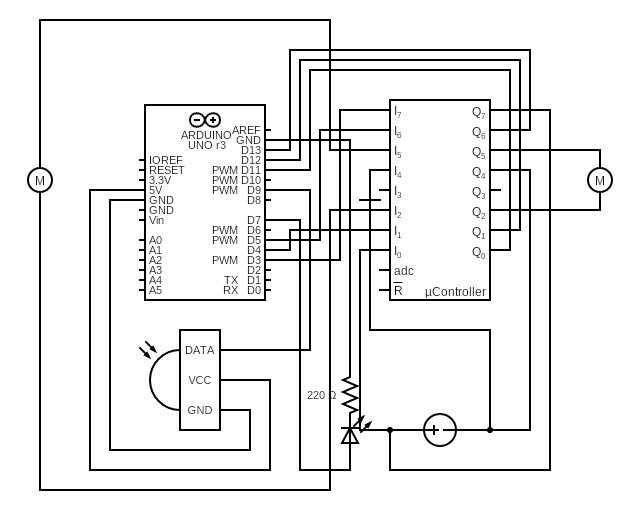
RC Car - Circuit Diagram
This is the circuit diagram for the Arduino RC car. The microprocessor in the diagram is the L293D chip, with row 7 of the chip corresponding to the same side as the notch at teh edge of the chip. If the motors spin in the wrong direction, switch around some of the the terminals of the motor (keep them on the same side of the L293D chip though).
RC Car - Circuit Diagram
Comments
Only logged in users can leave comments