Speedlight trigger - NEW
Device is a photo flash trigger that responds to sound, beam interruption, it works as a timer and controller for (drop) valves control.
Components and supplies
2.8 INCH TOUCH SCREEN FOR UNO/MEGA DEVELOPMENT BOARD WPSH412
Arduino UNO
Tools and machines
Soldering iron (generic)
Apps and platforms
Autodesk tinkercad.com
EasyEDA designer
Arduino IDE
Project description
Code
Timer_active.ino
arduino
1void setup_timer_active()
2{
3  tft.fillScreen(BLACK);
4  trigger_armed  = false ;
5  tft.drawRect(30, 20, 180, 90,  RED);
6  tft.drawRect(30, 140, 180,  90,  GREEN);
7  tft.drawRect(80, 255, 80, 50,  DARKGREY);
8  showText(107, 273  , 2, WHITE, BLACK, "<-") ;
9  trigger_apparence(20, 30);
10  pixel_x = 1, pixel_y  = 1 ;
11}
12
13//  ***************************************************************************************
14void  loop_timer_active()
15{
16  while (true)
17  {
18    if (Touch_getXY()) {
19      // arm area detection
20      if (pixel_x > 30 && pixel_x < 210 && pixel_y  > 20 && pixel_y < 110 && !trigger_armed) {
21        trigger_armed = true ;
22      }
23      // delayed and test area detection (only if not armed)
24      if  (pixel_x > 30 && pixel_x < 210 && pixel_y > 140 && pixel_y < 230 && !trigger_armed  ) {
25        tft.fillRect(31, 141, 178, 88,  GREEN);
26        digitalWrite(1,  HIGH);
27        trigger_portdrive() ;
28        delay(100) ;
29        digitalWrite(1,  LOW);
30        trigger_apparence(20, 30);
31      }
32      // cancel area detection
33      if (pixel_x > 70 && pixel_x < 170 && pixel_y > 255 && pixel_y < 305 ) break;
34    }
35    if (trigger_armed) {
36      trigger_apparence(20, 30);
37      timer_run();
38      trigger_armed = false ;
39      trigger_apparence(20, 30);
40      delay(300)  ;
41    }
42  }
43  pixel_x = 1, pixel_y = 1 ;
44}
45
46
47//  ***************************************************************************************
48void  timer_run()
49{
50  for (int i = 1 ; i <= unarm_after; i++) {
51    showText(100  , 150 , 2, WHITE, BLACK, String(i)) ;
52    showText(100 , 204 , 2, WHITE, BLACK,  String(delay_ms)) ;
53    delay(delay_ms);
54    digitalWrite(13, HIGH) ; // triger  DSLR on out 4 ;
55    tft.fillRect(100, 202, 100, 20,  BLACK);
56    showText(98  , 204 , 2, WHITE, BLACK, String(add_ms)) ;
57    for (int is = 1 ; is <= no_of_shots;  is++) {
58      digitalWrite(1, HIGH) ;
59      trigger_portdrive() ;
60      showText(98  , 177 , 2, WHITE, BLACK, String(is)) ;
61      digitalWrite(1, LOW) ;
62      delay(add_ms);
63      // cancel detection
64      if (Touch_getXY()) {
65        is = no_of_shots;
66        i  = unarm_after;
67      }
68    }
69    //    digitalWrite(1, LOW)  ;
70    digitalWrite(13, LOW) ; // OFF DSLR on out 4 ;
71  }
72}
73
Main menu code
arduino
1#include <Adafruit_GFX.h>
2#include <MCUFRIEND_kbv.h>
3MCUFRIEND_kbv  tft;
4#include <TouchScreen.h>
5
6#define MINPRESSURE  20
7#define MAXPRESSURE  900
8#define BLACK       0x0000      /*   0,   0,   0 */
9#define NAVY        0x000F      /*   0,   0, 128 */
10#define DARKGREEN   0x03E0      /*   0, 128,   0 */
11#define  DARKCYAN    0x03EF      /*   0, 128, 128 */
12#define MAROON      0x7800      /*  128,   0,   0 */
13#define PURPLE      0x780F      /* 128,   0, 128 */
14#define  OLIVE       0x7BE0      /* 128, 128,   0 */
15#define LIGHTGREY   0xC618      /*  192, 192, 192 */
16#define DARKGREY    0x7BEF      /* 128, 128, 128 */
17#define  BLUE        0x001F      /*   0,   0, 255 */
18#define GREEN       0x07E0      /*   0, 255,   0 */
19#define CYAN        0x07FF      /*   0, 255, 255 */
20#define  RED         0xF800      /* 255,   0,   0 */
21#define MAGENTA     0xF81F      /*  255,   0, 255 */
22#define YELLOW      0xFFE0      /* 255, 255,   0 */
23#define  WHITE       0xFFFF      /* 255, 255, 255 */
24#define ORANGE      0xFD20      /*  255, 165,   0 */
25#define GREENYELLOW 0xAFE5      /* 173, 255,  47 */
26#define  PINK        0xF81F
27
28// ALL Touch panels and wiring is DIFFERENT
29// copy-paste  results from TouchScreen_Calibr_native.ino
30// PORTRAIT  CALIBRATION     240 x  320
31//x = map(p.x, LEFT=916, RT=134, 0, 240)
32//y = map(p.y, TOP=90, BOT=912,  0, 320)
33//LANDSCAPE CALIBRATION     320 x 240
34//x = map(p.y, LEFT=90, RT=912,  0, 320)
35//y = map(p.x, TOP=134, BOT=916, 0, 240)
36
37const int XP = 8, XM  = A2, YP = A3, YM = 9; //240x320 ID=0x9341
38const int TS_LEFT = 916, TS_RT = 134,  TS_TOP = 90, TS_BOT = 912;
39
40TouchScreen ts = TouchScreen(XP, YP, XM, YM, 300);
41Adafruit_GFX_Button  ok, nok , cancel, btn1, btn2, btn3,
42                    n1, n2, n3, n4, n5, n6,  n7, n8, n9, n0, nclear , nback ;
43
44
45// **************************************************************************
46//  global varijables for trigger
47// **************************************************************************
48int  pixel_x, pixel_y;     //Touch_getXY()updates global vars
49int  tmrSelect = 0  , input_a = 0 ,
50     pot_h = 300 ,  slider_y = 200 , main_color = CYAN ;
51long  delay_ms , add_ms  , no_of_shots  , unarm_after ,
52     valve1 , valve2, numfield  = 0;
53bool updatefield = false , trigger_armed = false , trig_d1 , trig_d2, trig_d3  ;
54char* unit = "ms" ;
55//uint16_t main_color = CYAN ;
56
57#define pot_k  3.27 // 980 (cca 4.8V) analog steps / 300 slider height
58#define out_trig_imp  1200 // vidth of exit pulse in microsecond
59void setup()
60{
61  //  Serial.begin(9600);
62  pinMode(1, OUTPUT)     ;
63  pinMode(10, OUTPUT) ;
64  pinMode(11, OUTPUT) ;
65  pinMode(12, OUTPUT) ;
66  pinMode(13, OUTPUT) ;
67  uint16_t ID = tft.readID();
68  tft.begin(ID);
69  tft.setRotation(0); //PORTRAIT
70  redrav_main();
71}
72
73//  ***************************************************************************************
74void  loop()
75{
76  bool down = Touch_getXY();
77  btn1.press(down && btn1.contains(pixel_x,  pixel_y));
78  btn2.press(down && btn2.contains(pixel_x, pixel_y));
79  btn3.press(down  && btn3.contains(pixel_x, pixel_y));
80  if (btn1.justPressed()) {
81    btn1.drawButton(true);
82    tmrSelect = 1;
83    main_color = CYAN ;
84    delay_ms = 220 , add_ms = 0  , no_of_shots = 1, unarm_after = 1 ;
85    trig_d1 = true , trig_d2 = false , trig_d3  = false ;
86    setup_trigger();
87    loop_trigger();
88    redrav_main();
89  }
90  if (btn2.justPressed()) {
91    btn2.drawButton(true);
92    tmrSelect  = 2;
93    main_color = ORANGE ;
94    delay_ms = 2000 , add_ms = 1000 , no_of_shots  = 5 , unarm_after = 1 ;
95    trig_d1 = true , trig_d2 = false , trig_d3 = false  ;
96    setup_trigger();
97    loop_trigger();
98    redrav_main();
99  }
100  if (btn3.justPressed()) {
101    btn3.drawButton(true);
102    tmrSelect = 3 ;
103    main_color = GREEN ;
104    delay_ms = 2000 , add_ms = 100 , no_of_shots = 100,  unarm_after = 1 ,
105    valve1 = 25 , valve2 = 25 ;
106    trig_d1 = true , trig_d2  = true , trig_d3 = false ;
107    setup_trigger();
108    loop_trigger();
109    redrav_main();
110  }
111}
112
113//  ***************************************************************************************
114//  subrutine - function
115
116void redrav_main()
117{
118  tft.fillScreen(BLACK);
119  btn1.initButton(&tft,  120, 170, 140, 40, CYAN, CYAN, BLACK, "TRIGGER", 2);
120  btn2.initButton(&tft, 120, 230, 140, 40, ORANGE, ORANGE, BLACK, "TIMER", 2);
121  btn3.initButton(&tft, 120, 290, 140, 40, GREEN, GREEN, BLACK, "DROP", 2);
122  btn1.drawButton(false);
123  btn2.drawButton(false);
124  btn3.drawButton(false);
125  showText(77, 10, 3, WHITE, BLACK, "Photo") ;
126  showText(62, 40, 3, WHITE,  BLACK, "trigger") ;
127  showText(32, 80, 2, DARKCYAN, BLACK, "v:2.0  2010-21.")  ;
128  showText(52, 105, 2, DARKCYAN, BLACK, "Dusan Grbac") ;
129}
130
131bool  Touch_getXY()
132{
133  TSPoint p = ts.getPoint();
134  pinMode(YP, OUTPUT);      //restore  shared pins
135  pinMode(XM, OUTPUT);
136  digitalWrite(YP, HIGH);   //because TFT  control pins
137  digitalWrite(XM, HIGH);
138  bool pressed = (p.z > MINPRESSURE  && p.z < MAXPRESSURE);
139  if (pressed) {
140    pixel_x = map(p.x, TS_LEFT, TS_RT,  0, tft.width()); //.kbv makes sense to me
141    pixel_y = map(p.y, TS_TOP, TS_BOT,  0, tft.height());
142  }
143  return pressed;
144}
145
146
147void showText(int  x, int y, int sz , uint16_t color, uint16_t colorb , String msg)
148{
149  tft.setCursor(x,  y);
150  tft.setTextColor(color, colorb);
151  tft.setTextSize(sz);
152  tft.print(msg);
153}
154
Drop_timer.ino
arduino
1void setup_drop_timer_active()
2{
3  tft.fillScreen(BLACK);
4  trigger_armed  = false ;
5  tft.drawRect(30, 20, 180, 90,  RED);
6  tft.drawRect(30, 140, 180,  90,  GREEN);
7  tft.drawRect(80, 255, 80, 50,  DARKGREY);
8  showText(107, 273  , 2, WHITE, BLACK, "<-") ;
9  trigger_apparence(20, 30);
10  pixel_x = 1, pixel_y  = 1 ;
11}
12
13//  ***************************************************************************************
14void  loop_drop_timer_active()
15{
16  while (true)
17  {
18    if (Touch_getXY())  {
19      // arm area detection
20      if (pixel_x > 30 && pixel_x < 210 && pixel_y  > 20 && pixel_y < 110 && !trigger_armed) {
21        trigger_armed = true ;
22      }
23      // delayed and test area detection (only if not armed)
24      if  (pixel_x > 30 && pixel_x < 210 && pixel_y > 140 && pixel_y < 230 && !trigger_armed  ) {
25        tft.fillRect(31, 141, 178, 88,  GREEN);
26        digitalWrite(1,  HIGH);
27        trigger_portdrive() ;
28        delay(100) ;
29        digitalWrite(1,  LOW);
30        trigger_apparence(20, 30);
31      }
32      // cancel area detection
33      if (pixel_x > 70 && pixel_x < 170 && pixel_y > 255 && pixel_y < 305 ) break;
34    }
35    if (trigger_armed) {
36      trigger_apparence(20, 30);
37      drop_timer_run();
38      trigger_armed = false ;
39      trigger_apparence(20, 30);
40      delay(300)  ;
41    }
42  }
43  pixel_x = 1, pixel_y = 1 ;
44}
45
46//  ***************************************************************************************
47void  drop_timer_run()
48{
49  digitalWrite(13, HIGH) ; // triger DSLR on out 4 ;
50  delay(delay_ms);
51  digitalWrite(1, HIGH) ;
52  if (trig_d3) { // valve 1 and  valve 2 (out1 and out2) fire simultaneous
53    digitalWrite(10, HIGH) ;
54    digitalWrite(11,  HIGH);
55    delay(valve1) ;
56    digitalWrite(10, LOW) ;
57    digitalWrite(11,  LOW);
58    delay(no_of_shots);
59    digitalWrite(10, HIGH) ;
60    digitalWrite(11,  HIGH);
61    delay(valve2) ;
62    digitalWrite(10, LOW) ;
63    digitalWrite(11,  LOW) ;
64  } else {
65    if (trig_d1) {
66      digitalWrite(10, HIGH) ;
67      delay(valve1) ;
68      digitalWrite(10, LOW) ;
69    }
70    delay(no_of_shots);
71    if (trig_d2) {
72      digitalWrite(11, HIGH);
73      delay(valve2) ;
74      digitalWrite(11, LOW);
75    }
76  }
77  delay(add_ms);
78  digitalWrite(12,  HIGH);
79  delayMicroseconds(out_trig_imp) ;
80  digitalWrite(12, LOW);
81  digitalWrite(1,  LOW) ;
82  digitalWrite(13, LOW) ; // OFF DSLR on out 4
83}
84
Trigger_active.ino
arduino
1//  ***************************************************************************************
2//  sound and light trigger
3//  ***************************************************************************************
4void  setup_trigger_active()
5{
6  tft.fillScreen(BLACK);
7  trigger_armed = false  ;
8  tft.drawRect(10, 20, 150, 90,  RED); // activate button
9  tft.drawRect(10,  140, 150, 90,  GREEN); // test button
10  tft.drawRect(10, 255, 50, 50,  DARKGREY);  // cancel button
11  tft.drawRect(210, 10, 20, pot_h ,  DARKGREY); // sound-light  meter bar
12  tft.fillRect(177, pot_h - slider_y + 5, 30, 20, GREEN);
13  showText(23,  273 , 2, WHITE, BLACK, "<-") ;
14  showText(70, 261 , 1, GREEN, BLACK,  "max  <=300");
15  showText(70, 288 , 1, GREEN, BLACK,  "threshold")  ;
16  trigger_apparence(0,  0);
17  pixel_x = 1, pixel_y = 1 ;
18}
19
20//  ***************************************************************************************
21void  loop_triger_active()
22{
23  int input_lt = 0 ; // input latency
24  int input_max  = 0 ; // remeber max imput in one ciklus
25  while (true)
26  {
27    if (Touch_getXY())  {
28      // ARM area detection
29      if (pixel_x > 10 && pixel_x < 150 && pixel_y  > 20 && pixel_y < 110 ) {
30        trigger_armed = true ;
31        trigger_apparence(0,  0) ;
32      }
33      // TEST output area detection (only if not armed)
34      if  (pixel_x > 10 && pixel_x < 150 && pixel_y > 140 && pixel_y < 230 ) {
35        tft.fillRect(11,  141, 148, 88,  GREEN);
36        digitalWrite(1, HIGH);
37        trigger_portdrive()  ;
38        delay(100) ;
39        digitalWrite(1, LOW);
40        trigger_apparence(0,  0) ;
41      }
42      // SLIDER MOVE area detection (only if not armed)
43      if  (pixel_x > 170 && pixel_x < 240 && pixel_y > 10 && pixel_y < pot_h) {
44        tft.fillRect(177,  pot_h - slider_y + 5, 30, 20, BLACK);
45        slider_y = pot_h - (pixel_y - 10)  ;
46        tft.fillRect(177, pot_h - slider_y + 5, 30, 20, GREEN);
47      }
48      // cancel area detection
49      if (pixel_x > 10 && pixel_x < 110 && pixel_y  > 255 && pixel_y < 305 ) break ;
50    } else {
51      if (trigger_armed ) {
52        trigger_apparence(0, 0) ;
53        //***************************************************
54        trigger_active_run(); // activate triger wait
55        //***************************************************
56        trigger_armed = false ;
57        trigger_apparence(0, 0) ;
58        delay(300)  ;
59      }
60      input_a = analogRead(A5) ;
61      input_a = min(input_a  / pot_k, 300) ;
62      input_max = max(input_max, input_a) ;
63      input_lt  = input_lt + 1 ;
64      if  (input_lt > 130) {
65        int border = 11 + min(pot_h  - input_max , 298);
66        tft.fillRect(211, border , 18, pot_h - border + 11,  GREEN);
67        tft.fillRect(211, 11 , 18, border - 10 , BLACK);
68        tft.fillRect(137,  255, 36, 50,  BLACK);
69        showText(137, 258 , 2, WHITE, BLACK,  String(input_max))  ;
70        showText(137, 285 , 2, WHITE, BLACK,  String(slider_y)) ;
71        if  (input_max >= slider_y ) {
72          tft.fillRect(177, pot_h - slider_y + 5,  30, 20, RED);
73          digitalWrite(1, HIGH) ;
74          input_lt = input_lt  * -1.5;
75        } else {
76          tft.fillRect(177, pot_h - slider_y + 5,  30, 20, GREEN);
77          digitalWrite(1, LOW) ;
78          input_lt = 0 ;
79        }
80         delay(10);
81        input_max = 0 ;
82      }
83    }
84  }
85  pixel_x = 1, pixel_y = 1 ;
86}
87
88
89//  ***************************************************************************************
90void  trigger_active_run()
91{
92  long sum_delay = delay_ms ;
93  for (int i = 1 ;  i <= unarm_after; i++) { // no of ciclus
94    showText(70 , 150 , 2, WHITE, BLACK,  String(i)) ;
95    digitalWrite(13, HIGH) ; // DSLR ON out 4 ;
96    delay(400)  ; // delay for DSLR on port4 to stop vibrating
97    for (int is = 1 ; is <= no_of_shots  ; is++) {
98      showText(70 , 177 , 2, WHITE, BLACK, String(is)) ;
99      tft.fillRect(65,  202, 90, 20,  BLACK);
100      showText(70 , 204 , 2, WHITE, BLACK, String(sum_delay))  ;
101      // main trigger loop
102      //**********************************************
103      delay(10) ; // important delay for input A5 port to work !!
104      do {
105        input_a = analogRead(A5) ;
106        input_a = input_a / pot_k ;
107      }  while (input_a < slider_y ) ;
108      //**********************************************
109      digitalWrite(1, HIGH) ;
110      delay(sum_delay) ;
111      trigger_portdrive()  ;
112      sum_delay = sum_delay + add_ms ;
113    }
114 // delay(10) ; // delay  from shot to shot
115    digitalWrite(1, LOW) ;
116    digitalWrite(13, LOW) ; //  OFF DSLR on out 4 ;
117    if (unarm_after > 1) delay(800) ; // general delay from  shot to shot for DSLR por4 for multiple cycles
118  }
119}
120
Trigger.ino
arduino
1// Main screen for time setting, number of shots and output selection
2
3void  setup_trigger()
4{
5  tft.fillScreen(BLACK);
6  char* title = "" ;
7  int  hline = 52 , yline = 10 ;
8  switch (tmrSelect) {
9    case 1 :
10      title  = "Trigger" ;
11      showText(5, yline , 1, DARKGREY, BLACK,             "delay  after TRIGGER (ms)") ;
12      showText(5, yline + hline , 1, DARKGREY, BLACK,     "number of shots in one cycle (no)") ;
13      showText(5, yline + hline  * 2 , 1, DARKGREY, BLACK, "add after each cycle or shot (ms)") ;
14      showText(5,  yline + hline * 3 , 1, DARKGREY, BLACK, "unarm after X cycles - camera off (no)")  ;
15      break;
16    case 2 :
17      title = " Timer" ;
18      showText(5,  yline , 1, DARKGREY, BLACK,             "delay after ACTIVATE cycle (ms)") ;
19      showText(5, yline + hline , 1, DARKGREY, BLACK,     "number of shots in one  cycle (no)") ;
20      showText(5, yline + hline * 2 , 1, DARKGREY, BLACK, "delay  between shots (ms)") ;
21      showText(5, yline + hline * 3 , 1, DARKGREY, BLACK,  "repeat timer cycle (no)") ;
22      break;
23    case 3 :
24      title =  " Drop" ;
25      showText(5, yline , 1, DARKGREY, BLACK,             "delay  to activate Out1(ms) - valve 1") ;
26      showText(5, yline + hline , 1, DARKGREY,  BLACK,     "delay to activate Out2(ms) - valve 2") ;
27      showText(5, yline  + hline * 2 , 1, DARKGREY, BLACK, "delay to activate Out3(ms) - flash") ;
28      showText(5, yline + hline * 3 , 1, DARKGREY, BLACK, "puls(ms)    valve 1   -    valve 2") ;
29      break;
30  }
31  // ---- buttons
32  tft.drawRect(15,  228, 55, 36,  DARKGREY); // output button 1
33  tft.drawRect(95, 228, 55, 36,  DARKGREY);  // output button 2
34  tft.drawRect(175, 228, 55, 36,  DARKGREY); // output button  3
35
36  tft.drawRect(15, 280, 60, 36,  DARKGREY); // cancel button
37  showText(30,  290 , 2, WHITE, BLACK, "<-") ;
38  tft.fillRect(100, 280, 130, 36,  main_color);  // trigger button
39  showText(125, 290 , 2, BLACK , main_color, String(title))  ;
40  output_button() ;
41  pixel_x = 1, pixel_y = 1 ;
42}
43
44//  ***************************************************************************************
45//  main loop for number enter and activate sound,light triger, timer and drop timer
46//  ***************************************************************************************
47void  loop_trigger()
48{
49  while (true)
50  {
51    // ----- variables
52    int  hline = 52 , yline = 30;
53    showText(30, yline , 3 , main_color, BLACK , String(delay_ms))  ;
54    showText(30, yline + hline , 3 , main_color, BLACK, String(no_of_shots))  ;
55    showText(30, yline + hline * 2 , 3 , main_color, BLACK, String(add_ms))  ;
56    if (tmrSelect == 3) {
57      showText(80, yline + hline * 3 , 3 , main_color,  BLACK, String(valve1)) ;
58      showText(170, yline + hline * 3 , 3 , main_color,  BLACK, String(valve2)) ;
59    } else {
60      showText(30, yline + hline * 3  , 3 , main_color, BLACK, String(unarm_after)) ;
61    }
62    if (Touch_getXY())  {
63      // triger button detection
64      if (pixel_x > 100 && pixel_x < 230  && pixel_y > 280 && pixel_y < 320) {
65        switch (tmrSelect) {
66          case  1 :
67            setup_trigger_active();
68            loop_triger_active();
69            break;
70          case 2 :
71            setup_timer_active();
72            loop_timer_active();
73            break;
74          case 3 :
75            setup_drop_timer_active();
76            loop_drop_timer_active();
77            break;
78        }
79        setup_trigger();
80      }
81      if  (pixel_x > 15 && pixel_x < 75 && pixel_y > 280 && pixel_y < 315) break ;
82      touch_detect()  ;
83      delay(20);
84    }
85  }
86  pixel_x = 1, pixel_y = 1 ;
87}
88
89
90//  ***************************************************************************************
91//  function for screen touch detection
92//  ***************************************************************************************
93void  touch_detect() {
94  int hline = 52 , yline = 30;
95  // 1. line detection
96  if (pixel_x > 30 && pixel_x < 200 && pixel_y > yline - 20 && pixel_y < yline +  20) {
97    unit = "ms";
98    numfield = delay_ms;
99    setup_num();
100    loop_num();
101    if (updatefield) delay_ms = numfield ;
102    setup_trigger();
103  }
104  // 2. line detection
105  if (pixel_x > 30 && pixel_x < 200 && pixel_y  > yline + hline - 20 && pixel_y < yline + hline + 20) {
106    unit = "no";
107    numfield = no_of_shots;
108    setup_num();
109    loop_num();
110    if (updatefield)  no_of_shots = numfield ;
111    setup_trigger();
112  }
113  // 3. line detection
114  if (pixel_x > 30 && pixel_x < 200 && pixel_y > yline + (hline * 2) - 20 && pixel_y  < yline + (hline * 2) + 20) {
115    unit = "ms";
116    numfield = add_ms;
117    setup_num();
118    loop_num();
119    if (updatefield) add_ms = numfield ;
120    setup_trigger();
121  }
122  // 4. line detection
123  if (tmrSelect == 3) {
124    if (pixel_x > 30 && pixel_x < 120 && pixel_y > yline + (hline * 3) - 20 && pixel_y  < yline + (hline * 3) + 20) {
125      unit = "ms";
126      numfield = valve1;
127      setup_num();
128      loop_num();
129      if (updatefield) valve1 = numfield  ;
130      setup_trigger();
131    }
132    if (pixel_x > 150 && pixel_x < 210 &&  pixel_y > yline + (hline * 3) - 20 && pixel_y < yline + (hline * 3) + 20) {
133      unit = "ms";
134      numfield = valve2;
135      setup_num();
136      loop_num();
137      if (updatefield) valve2 = numfield ;
138      setup_trigger();
139    }
140  } else {
141    if (pixel_x > 30 && pixel_x < 200 && pixel_y > yline + (hline  * 3) - 20 && pixel_y < yline + (hline * 3) + 20) {
142      unit = "no";
143      numfield  = unarm_after;
144      setup_num();
145      loop_num();
146      if (updatefield)  unarm_after = numfield ;
147      setup_trigger();
148    }
149  }
150  if (pixel_x  > 15 && pixel_x < 70 && pixel_y > 228 && pixel_y < 266) {
151    trig_d1 = !trig_d1  ;
152    if (tmrSelect == 3 && trig_d1 ) trig_d3 = false ;
153    output_button()  ;
154  }
155  if (pixel_x > 95 && pixel_x < 150 && pixel_y > 228 && pixel_y < 266)  {
156    trig_d2 = !trig_d2 ;
157    if (tmrSelect == 3 && trig_d2 ) trig_d3 = false  ;
158    output_button() ;
159  }
160  if (pixel_x > 175 && pixel_x < 230 && pixel_y  > 228 && pixel_y < 266) {
161    trig_d3 = !trig_d3 ;
162    if (tmrSelect == 3  && trig_d3 ) trig_d1 = false, trig_d2 = false ;
163    output_button() ;
164  }
165}
166//  ***************************************************************************************
167//  function for output button driving
168//  ***************************************************************************************
169void  output_button() {
170  if (!trig_d1) {
171    tft.fillRect(16, 229 , 53, 34, BLACK);
172    showText(39, 240 , 2, DARKGREY, BLACK, "1") ;
173  } else {
174    tft.fillRect(16,  229 , 53, 34, main_color);
175    showText(39, 240 , 2, BLACK, BLACK, "1") ;
176  }
177  if (!trig_d2) {
178    tft.fillRect(96, 229, 53, 34,  BLACK);
179    showText(118,  240 , 2, DARKGREY, BLACK, "2") ;
180  } else {
181    tft.fillRect(96, 229, 53,  34,  main_color);
182    showText(118, 240 , 2, BLACK, BLACK, "2") ;
183  }
184  if (!trig_d3) {
185    tft.fillRect(176, 229, 53, 34,  BLACK);
186    if (tmrSelect  == 3) {
187      showText(185, 240 , 2, DARKGREY, BLACK, "1+2") ;
188    } else  {
189      showText(198, 240 , 2, DARKGREY, BLACK, "3") ;
190    }
191  } else  {
192    tft.fillRect(176, 229, 53, 34,  main_color);
193    if (tmrSelect == 3)  {
194      showText(185, 240 , 2, BLACK, BLACK, "1+2") ;
195    } else {
196      showText(198,  240 , 2, BLACK, BLACK, "3") ;
197    }
198  }
199  delay(200);
200}
201
202
203//  ***************************************************************************************
204//  function for port driving
205//  ***************************************************************************************
206void  trigger_portdrive() {
207  if (trig_d1 ) digitalWrite(10, HIGH);
208  if (trig_d2  ) digitalWrite(11, HIGH);
209  if (trig_d3 ) digitalWrite(12, HIGH);
210  delayMicroseconds(out_trig_imp);
211  digitalWrite(10, LOW);
212  digitalWrite(11, LOW);
213  digitalWrite(12, LOW);
214}
215
216//  ***************************************************************************************
217//  function for button redrive (button test and arm)
218//  ***************************************************************************************
219void  trigger_apparence(int xplus , int  wplus)
220{
221  if (trigger_armed) {
222    tft.fillRect(11  + xplus, 21, 148 + wplus, 88,  RED);
223    showText(52 + wplus, 60 , 2, BLACK,  BLACK,  "ACTIVE") ;
224    tft.fillRect(11 + xplus, 141, 148 + wplus, 88,  BLACK);
225    if (tmrSelect != 3) {
226      showText(20 + wplus, 155 , 1, GREEN, BLACK, "cycle  :") ;
227      showText(20 + wplus, 180 , 1, GREEN, BLACK, "shot  :") ;
228      showText(20  + wplus, 207 , 1, GREEN, BLACK, "delay :") ;
229    }
230  } else {
231    tft.fillRect(11  + xplus, 21, 148 + wplus, 88,  BLACK);
232    showText(41 + wplus, 60 , 2, WHITE,  BLACK, "ACTIVATE") ;
233    tft.fillRect(11 + xplus, 141, 148 + wplus, 88,  BLACK);
234    showText(66 + wplus, 180 , 2, WHITE, BLACK, "TEST") ;
235  }
236}
237
Timer_active.ino
arduino
1void setup_timer_active()
2{
3  tft.fillScreen(BLACK);
4  trigger_armed   = false ;
5  tft.drawRect(30, 20, 180, 90,  RED);
6  tft.drawRect(30, 140, 180,   90,  GREEN);
7  tft.drawRect(80, 255, 80, 50,  DARKGREY);
8  showText(107, 273   , 2, WHITE, BLACK, "<-") ;
9  trigger_apparence(20, 30);
10  pixel_x = 1, pixel_y   = 1 ;
11}
12
13//  ***************************************************************************************
14void   loop_timer_active()
15{
16  while (true)
17  {
18    if (Touch_getXY()) {
19       // arm area detection
20      if (pixel_x > 30 && pixel_x < 210 && pixel_y   > 20 && pixel_y < 110 && !trigger_armed) {
21        trigger_armed = true ;
22       }
23      // delayed and test area detection (only if not armed)
24      if   (pixel_x > 30 && pixel_x < 210 && pixel_y > 140 && pixel_y < 230 && !trigger_armed   ) {
25        tft.fillRect(31, 141, 178, 88,  GREEN);
26        digitalWrite(1,   HIGH);
27        trigger_portdrive() ;
28        delay(100) ;
29        digitalWrite(1,   LOW);
30        trigger_apparence(20, 30);
31      }
32      // cancel area detection
33       if (pixel_x > 70 && pixel_x < 170 && pixel_y > 255 && pixel_y < 305 ) break;
34     }
35    if (trigger_armed) {
36      trigger_apparence(20, 30);
37      timer_run();
38       trigger_armed = false ;
39      trigger_apparence(20, 30);
40      delay(300)   ;
41    }
42  }
43  pixel_x = 1, pixel_y = 1 ;
44}
45
46
47//  ***************************************************************************************
48void   timer_run()
49{
50  for (int i = 1 ; i <= unarm_after; i++) {
51    showText(100   , 150 , 2, WHITE, BLACK, String(i)) ;
52    showText(100 , 204 , 2, WHITE, BLACK,   String(delay_ms)) ;
53    delay(delay_ms);
54    digitalWrite(13, HIGH) ; // triger   DSLR on out 4 ;
55    tft.fillRect(100, 202, 100, 20,  BLACK);
56    showText(98   , 204 , 2, WHITE, BLACK, String(add_ms)) ;
57    for (int is = 1 ; is <= no_of_shots;   is++) {
58      digitalWrite(1, HIGH) ;
59      trigger_portdrive() ;
60      showText(98   , 177 , 2, WHITE, BLACK, String(is)) ;
61      digitalWrite(1, LOW) ;
62      delay(add_ms);
63       // cancel detection
64      if (Touch_getXY()) {
65        is = no_of_shots;
66         i  = unarm_after;
67      }
68    }
69    //    digitalWrite(1, LOW)   ;
70    digitalWrite(13, LOW) ; // OFF DSLR on out 4 ;
71  }
72}
73
Trigger_active.ino
arduino
1//  ***************************************************************************************
2//   sound and light trigger
3//  ***************************************************************************************
4void   setup_trigger_active()
5{
6  tft.fillScreen(BLACK);
7  trigger_armed = false   ;
8  tft.drawRect(10, 20, 150, 90,  RED); // activate button
9  tft.drawRect(10,   140, 150, 90,  GREEN); // test button
10  tft.drawRect(10, 255, 50, 50,  DARKGREY);   // cancel button
11  tft.drawRect(210, 10, 20, pot_h ,  DARKGREY); // sound-light   meter bar
12  tft.fillRect(177, pot_h - slider_y + 5, 30, 20, GREEN);
13  showText(23,   273 , 2, WHITE, BLACK, "<-") ;
14  showText(70, 261 , 1, GREEN, BLACK,  "max   <=300");
15  showText(70, 288 , 1, GREEN, BLACK,  "threshold")  ;
16  trigger_apparence(0,   0);
17  pixel_x = 1, pixel_y = 1 ;
18}
19
20//  ***************************************************************************************
21void   loop_triger_active()
22{
23  int input_lt = 0 ; // input latency
24  int input_max   = 0 ; // remeber max imput in one ciklus
25  while (true)
26  {
27    if (Touch_getXY())   {
28      // ARM area detection
29      if (pixel_x > 10 && pixel_x < 150 && pixel_y   > 20 && pixel_y < 110 ) {
30        trigger_armed = true ;
31        trigger_apparence(0,   0) ;
32      }
33      // TEST output area detection (only if not armed)
34      if   (pixel_x > 10 && pixel_x < 150 && pixel_y > 140 && pixel_y < 230 ) {
35        tft.fillRect(11,   141, 148, 88,  GREEN);
36        digitalWrite(1, HIGH);
37        trigger_portdrive()   ;
38        delay(100) ;
39        digitalWrite(1, LOW);
40        trigger_apparence(0,   0) ;
41      }
42      // SLIDER MOVE area detection (only if not armed)
43      if   (pixel_x > 170 && pixel_x < 240 && pixel_y > 10 && pixel_y < pot_h) {
44        tft.fillRect(177,   pot_h - slider_y + 5, 30, 20, BLACK);
45        slider_y = pot_h - (pixel_y - 10)   ;
46        tft.fillRect(177, pot_h - slider_y + 5, 30, 20, GREEN);
47      }
48       // cancel area detection
49      if (pixel_x > 10 && pixel_x < 110 && pixel_y   > 255 && pixel_y < 305 ) break ;
50    } else {
51      if (trigger_armed ) {
52         trigger_apparence(0, 0) ;
53        //***************************************************
54         trigger_active_run(); // activate triger wait
55        //***************************************************
56         trigger_armed = false ;
57        trigger_apparence(0, 0) ;
58        delay(300)   ;
59      }
60      input_a = analogRead(A5) ;
61      input_a = min(input_a   / pot_k, 300) ;
62      input_max = max(input_max, input_a) ;
63      input_lt   = input_lt + 1 ;
64      if  (input_lt > 130) {
65        int border = 11 + min(pot_h   - input_max , 298);
66        tft.fillRect(211, border , 18, pot_h - border + 11,   GREEN);
67        tft.fillRect(211, 11 , 18, border - 10 , BLACK);
68        tft.fillRect(137,   255, 36, 50,  BLACK);
69        showText(137, 258 , 2, WHITE, BLACK,  String(input_max))   ;
70        showText(137, 285 , 2, WHITE, BLACK,  String(slider_y)) ;
71        if   (input_max >= slider_y ) {
72          tft.fillRect(177, pot_h - slider_y + 5,   30, 20, RED);
73          digitalWrite(1, HIGH) ;
74          input_lt = input_lt   * -1.5;
75        } else {
76          tft.fillRect(177, pot_h - slider_y + 5,   30, 20, GREEN);
77          digitalWrite(1, LOW) ;
78          input_lt = 0 ;
79         }
80         delay(10);
81        input_max = 0 ;
82      }
83    }
84   }
85  pixel_x = 1, pixel_y = 1 ;
86}
87
88
89//  ***************************************************************************************
90void   trigger_active_run()
91{
92  long sum_delay = delay_ms ;
93  for (int i = 1 ;   i <= unarm_after; i++) { // no of ciclus
94    showText(70 , 150 , 2, WHITE, BLACK,   String(i)) ;
95    digitalWrite(13, HIGH) ; // DSLR ON out 4 ;
96    delay(400)   ; // delay for DSLR on port4 to stop vibrating
97    for (int is = 1 ; is <= no_of_shots   ; is++) {
98      showText(70 , 177 , 2, WHITE, BLACK, String(is)) ;
99      tft.fillRect(65,   202, 90, 20,  BLACK);
100      showText(70 , 204 , 2, WHITE, BLACK, String(sum_delay))   ;
101      // main trigger loop
102      //**********************************************
103       delay(10) ; // important delay for input A5 port to work !!
104      do {
105         input_a = analogRead(A5) ;
106        input_a = input_a / pot_k ;
107      }   while (input_a < slider_y ) ;
108      //**********************************************
109       digitalWrite(1, HIGH) ;
110      delay(sum_delay) ;
111      trigger_portdrive()   ;
112      sum_delay = sum_delay + add_ms ;
113    }
114 // delay(10) ; // delay   from shot to shot
115    digitalWrite(1, LOW) ;
116    digitalWrite(13, LOW) ; //   OFF DSLR on out 4 ;
117    if (unarm_after > 1) delay(800) ; // general delay from   shot to shot for DSLR por4 for multiple cycles
118  }
119}
120
Num_enter.ino
arduino
1void setup_num()
2{
3  updatefield = false;
4  tft.fillScreen(BLACK);
5   int xb = 42, yb = 110, hbspa = 78, vbspa = 47, wb = 60, hb = 36 ;
6  nclear.initButton(&tft,   xb , yb, wb, hb, DARKGREY, BLACK, RED, "C", 2);
7  nback.initButton(&tft, xb   + hbspa * 2, yb, wb, hb, DARKGREY, BLACK, ORANGE, "<", 2);
8  n1.initButton(&tft,   xb, yb + vbspa, wb, hb, CYAN, CYAN, BLACK, "1", 3);
9  n2.initButton(&tft, xb   + hbspa, yb + vbspa, wb, hb, CYAN, CYAN, BLACK, "2", 3);
10  n3.initButton(&tft,   xb + hbspa * 2, yb + vbspa, wb, hb, CYAN, CYAN, BLACK, "3", 3);
11  n4.initButton(&tft,   xb, yb + vbspa * 2, wb, hb, CYAN, CYAN, BLACK, "4", 3);
12  n5.initButton(&tft,   xb + hbspa, yb + vbspa * 2, wb, hb, CYAN, CYAN, BLACK, "5", 3);
13  n6.initButton(&tft,   xb + hbspa * 2, yb + vbspa * 2, wb, hb, CYAN, CYAN, BLACK, "6", 3);
14  n7.initButton(&tft,   xb, yb + vbspa * 3, wb, hb, CYAN, CYAN, BLACK, "7", 3);
15  n8.initButton(&tft,   xb + hbspa, yb + vbspa * 3, wb, hb, CYAN, CYAN, BLACK, "8", 3);
16  n9.initButton(&tft,   xb + hbspa * 2, yb + vbspa * 3, wb, hb, CYAN, CYAN, BLACK, "9", 3);
17  n0.initButton(&tft,   xb + hbspa, yb + vbspa * 4, wb, hb, CYAN, CYAN, BLACK, "0", 3);
18  nok.initButton(&tft,   xb  , yb + vbspa * 4, wb, hb, DARKGREY, BLACK, WHITE, "<-", 2);
19  ok.initButton(&tft,   xb + hbspa * 2, yb + vbspa * 4, wb, hb, DARKGREY, BLACK, GREEN, "ok", 2);
20   n1.drawButton(false);
21  n2.drawButton(false);
22  n3.drawButton(false);
23   n4.drawButton(false);
24  n5.drawButton(false);
25  n6.drawButton(false);
26   n7.drawButton(false);
27  n8.drawButton(false);
28  n9.drawButton(false);
29   n0.drawButton(false);
30  nclear.drawButton(false);
31  nback.drawButton(false);
32   nok.drawButton(false);
33  ok.drawButton(false);
34  tft.drawRect(10, 10, 220,   70, DARKGREY);
35  pixel_x = 1, pixel_y = 1 ;
36}
37
38//  ***************************************************************************************
39
40void   loop_num()
41{
42  while (true)
43  {
44    bool down = Touch_getXY();
45    nback.press(down   && nback.contains(pixel_x, pixel_y));
46    nclear.press(down && nclear.contains(pixel_x,   pixel_y));
47    n1.press(down && n1.contains(pixel_x, pixel_y));
48    n2.press(down   && n2.contains(pixel_x, pixel_y));
49    n3.press(down && n3.contains(pixel_x,   pixel_y));
50    n4.press(down && n4.contains(pixel_x, pixel_y));
51    n5.press(down   && n5.contains(pixel_x, pixel_y));
52    n6.press(down && n6.contains(pixel_x,   pixel_y));
53    n7.press(down && n7.contains(pixel_x, pixel_y));
54    n8.press(down   && n8.contains(pixel_x, pixel_y));
55    n9.press(down && n9.contains(pixel_x,   pixel_y));
56    n0.press(down && n0.contains(pixel_x, pixel_y));
57    ok.press(down   && ok.contains(pixel_x, pixel_y));
58    nok.press(down && nok.contains(pixel_x,   pixel_y));
59    if (n1.justPressed()) {
60      numfield = (numfield * 10) +   1; //Pressed again
61      delay(150);
62    }
63    if (n2.justPressed()) {
64       numfield = (numfield * 10) + 2; //Pressed again
65      delay(150);
66    }
67     if (n3.justPressed()) {
68      numfield = (numfield * 10) + 3; //Pressed again
69       delay(150);
70    }
71    if (n4.justPressed()) {
72      numfield = (numfield   * 10) + 4; //Pressed again
73      delay(150);
74    }
75    if (n5.justPressed())   {
76      numfield = (numfield * 10) + 5; //Pressed again
77      delay(150);
78     }
79    if (n6.justPressed()) {
80      numfield = (numfield * 10) + 6; //Pressed   again
81      delay(150);
82    }
83    if (n7.justPressed()) {
84      numfield   = (numfield * 10) + 7; //Pressed again
85      delay(150);
86    }
87    if (n8.justPressed())   {
88      numfield = (numfield * 10) + 8; //Pressed again
89      delay(150);
90     }
91    if (n9.justPressed()) {
92      numfield = (numfield * 10) + 9; //Pressed   again
93      delay(150);
94    }
95    if (n0.justPressed()) {
96      if (numfield   > 0) {
97        numfield = (numfield * 10); //Pressed again
98      }
99      delay(150);
100     }
101    if (nback.justPressed()) {
102      tft.fillRect(12, 12, 216, 66,  BLACK);
103       unsigned lastd = numfield % 10;
104      numfield = (numfield - lastd) / 10;
105       delay(150);
106    }
107    if (nclear.justPressed()) {
108      tft.fillRect(12,   12, 216, 66,  BLACK);
109      numfield = 0 ;
110      delay(150);
111    }
112     if (nok.justPressed()) {
113      updatefield = false;
114      break ;
115     }
116    if (ok.justPressed()) {
117      updatefield = true;
118      break   ;
119    }
120    showText(190, 15, 2, DARKGREY, BLACK, unit) ;
121    showText(30,   40, 4, WHITE, BLACK, String(numfield)) ;
122  }
123  pixel_x = 1, pixel_y = 1 ;
124}
125
Drop_timer.ino
arduino
1void setup_drop_timer_active()
2{
3  tft.fillScreen(BLACK);
4  trigger_armed
5  = false ;
6  tft.drawRect(30, 20, 180, 90,  RED);
7  tft.drawRect(30, 140, 180,
8  90,  GREEN);
9  tft.drawRect(80, 255, 80, 50,  DARKGREY);
10  showText(107, 273
11  , 2, WHITE, BLACK, "<-") ;
12  trigger_apparence(20, 30);
13  pixel_x = 1, pixel_y
14  = 1 ;
15}
16
17//  ***************************************************************************************
18void
19  loop_drop_timer_active()
20{
21  while (true)
22  {
23    if (Touch_getXY())
24  {
25      // arm area detection
26      if (pixel_x > 30 && pixel_x < 210 && pixel_y
27  > 20 && pixel_y < 110 && !trigger_armed) {
28        trigger_armed = true ;
29
30      }
31      // delayed and test area detection (only if not armed)
32      if
33  (pixel_x > 30 && pixel_x < 210 && pixel_y > 140 && pixel_y < 230 && !trigger_armed
34  ) {
35        tft.fillRect(31, 141, 178, 88,  GREEN);
36        digitalWrite(1,
37  HIGH);
38        trigger_portdrive() ;
39        delay(100) ;
40        digitalWrite(1,
41  LOW);
42        trigger_apparence(20, 30);
43      }
44      // cancel area detection
45
46      if (pixel_x > 70 && pixel_x < 170 && pixel_y > 255 && pixel_y < 305 ) break;
47
48    }
49    if (trigger_armed) {
50      trigger_apparence(20, 30);
51      drop_timer_run();
52
53      trigger_armed = false ;
54      trigger_apparence(20, 30);
55      delay(300)
56  ;
57    }
58  }
59  pixel_x = 1, pixel_y = 1 ;
60}
61
62//  ***************************************************************************************
63void
64  drop_timer_run()
65{
66  digitalWrite(13, HIGH) ; // triger DSLR on out 4 ;
67
68  delay(delay_ms);
69  digitalWrite(1, HIGH) ;
70  if (trig_d3) { // valve 1 and
71  valve 2 (out1 and out2) fire simultaneous
72    digitalWrite(10, HIGH) ;
73    digitalWrite(11,
74  HIGH);
75    delay(valve1) ;
76    digitalWrite(10, LOW) ;
77    digitalWrite(11,
78  LOW);
79    delay(no_of_shots);
80    digitalWrite(10, HIGH) ;
81    digitalWrite(11,
82  HIGH);
83    delay(valve2) ;
84    digitalWrite(10, LOW) ;
85    digitalWrite(11,
86  LOW) ;
87  } else {
88    if (trig_d1) {
89      digitalWrite(10, HIGH) ;
90
91      delay(valve1) ;
92      digitalWrite(10, LOW) ;
93    }
94    delay(no_of_shots);
95
96    if (trig_d2) {
97      digitalWrite(11, HIGH);
98      delay(valve2) ;
99
100      digitalWrite(11, LOW);
101    }
102  }
103  delay(add_ms);
104  digitalWrite(12,
105  HIGH);
106  delayMicroseconds(out_trig_imp) ;
107  digitalWrite(12, LOW);
108  digitalWrite(1,
109  LOW) ;
110  digitalWrite(13, LOW) ; // OFF DSLR on out 4
111}
112
Num_enter.ino
arduino
1void setup_num()
2{
3  updatefield = false;
4  tft.fillScreen(BLACK);
5  int xb = 42, yb = 110, hbspa = 78, vbspa = 47, wb = 60, hb = 36 ;
6  nclear.initButton(&tft,  xb , yb, wb, hb, DARKGREY, BLACK, RED, "C", 2);
7  nback.initButton(&tft, xb  + hbspa * 2, yb, wb, hb, DARKGREY, BLACK, ORANGE, "<", 2);
8  n1.initButton(&tft,  xb, yb + vbspa, wb, hb, CYAN, CYAN, BLACK, "1", 3);
9  n2.initButton(&tft, xb  + hbspa, yb + vbspa, wb, hb, CYAN, CYAN, BLACK, "2", 3);
10  n3.initButton(&tft,  xb + hbspa * 2, yb + vbspa, wb, hb, CYAN, CYAN, BLACK, "3", 3);
11  n4.initButton(&tft,  xb, yb + vbspa * 2, wb, hb, CYAN, CYAN, BLACK, "4", 3);
12  n5.initButton(&tft,  xb + hbspa, yb + vbspa * 2, wb, hb, CYAN, CYAN, BLACK, "5", 3);
13  n6.initButton(&tft,  xb + hbspa * 2, yb + vbspa * 2, wb, hb, CYAN, CYAN, BLACK, "6", 3);
14  n7.initButton(&tft,  xb, yb + vbspa * 3, wb, hb, CYAN, CYAN, BLACK, "7", 3);
15  n8.initButton(&tft,  xb + hbspa, yb + vbspa * 3, wb, hb, CYAN, CYAN, BLACK, "8", 3);
16  n9.initButton(&tft,  xb + hbspa * 2, yb + vbspa * 3, wb, hb, CYAN, CYAN, BLACK, "9", 3);
17  n0.initButton(&tft,  xb + hbspa, yb + vbspa * 4, wb, hb, CYAN, CYAN, BLACK, "0", 3);
18  nok.initButton(&tft,  xb  , yb + vbspa * 4, wb, hb, DARKGREY, BLACK, WHITE, "<-", 2);
19  ok.initButton(&tft,  xb + hbspa * 2, yb + vbspa * 4, wb, hb, DARKGREY, BLACK, GREEN, "ok", 2);
20  n1.drawButton(false);
21  n2.drawButton(false);
22  n3.drawButton(false);
23  n4.drawButton(false);
24  n5.drawButton(false);
25  n6.drawButton(false);
26  n7.drawButton(false);
27  n8.drawButton(false);
28  n9.drawButton(false);
29  n0.drawButton(false);
30  nclear.drawButton(false);
31  nback.drawButton(false);
32  nok.drawButton(false);
33  ok.drawButton(false);
34  tft.drawRect(10, 10, 220,  70, DARKGREY);
35  pixel_x = 1, pixel_y = 1 ;
36}
37
38//  ***************************************************************************************
39
40void  loop_num()
41{
42  while (true)
43  {
44    bool down = Touch_getXY();
45    nback.press(down  && nback.contains(pixel_x, pixel_y));
46    nclear.press(down && nclear.contains(pixel_x,  pixel_y));
47    n1.press(down && n1.contains(pixel_x, pixel_y));
48    n2.press(down  && n2.contains(pixel_x, pixel_y));
49    n3.press(down && n3.contains(pixel_x,  pixel_y));
50    n4.press(down && n4.contains(pixel_x, pixel_y));
51    n5.press(down  && n5.contains(pixel_x, pixel_y));
52    n6.press(down && n6.contains(pixel_x,  pixel_y));
53    n7.press(down && n7.contains(pixel_x, pixel_y));
54    n8.press(down  && n8.contains(pixel_x, pixel_y));
55    n9.press(down && n9.contains(pixel_x,  pixel_y));
56    n0.press(down && n0.contains(pixel_x, pixel_y));
57    ok.press(down  && ok.contains(pixel_x, pixel_y));
58    nok.press(down && nok.contains(pixel_x,  pixel_y));
59    if (n1.justPressed()) {
60      numfield = (numfield * 10) +  1; //Pressed again
61      delay(150);
62    }
63    if (n2.justPressed()) {
64      numfield = (numfield * 10) + 2; //Pressed again
65      delay(150);
66    }
67    if (n3.justPressed()) {
68      numfield = (numfield * 10) + 3; //Pressed again
69      delay(150);
70    }
71    if (n4.justPressed()) {
72      numfield = (numfield  * 10) + 4; //Pressed again
73      delay(150);
74    }
75    if (n5.justPressed())  {
76      numfield = (numfield * 10) + 5; //Pressed again
77      delay(150);
78    }
79    if (n6.justPressed()) {
80      numfield = (numfield * 10) + 6; //Pressed  again
81      delay(150);
82    }
83    if (n7.justPressed()) {
84      numfield  = (numfield * 10) + 7; //Pressed again
85      delay(150);
86    }
87    if (n8.justPressed())  {
88      numfield = (numfield * 10) + 8; //Pressed again
89      delay(150);
90    }
91    if (n9.justPressed()) {
92      numfield = (numfield * 10) + 9; //Pressed  again
93      delay(150);
94    }
95    if (n0.justPressed()) {
96      if (numfield  > 0) {
97        numfield = (numfield * 10); //Pressed again
98      }
99      delay(150);
100    }
101    if (nback.justPressed()) {
102      tft.fillRect(12, 12, 216, 66,  BLACK);
103      unsigned lastd = numfield % 10;
104      numfield = (numfield - lastd) / 10;
105      delay(150);
106    }
107    if (nclear.justPressed()) {
108      tft.fillRect(12,  12, 216, 66,  BLACK);
109      numfield = 0 ;
110      delay(150);
111    }
112    if (nok.justPressed()) {
113      updatefield = false;
114      break ;
115    }
116    if (ok.justPressed()) {
117      updatefield = true;
118      break  ;
119    }
120    showText(190, 15, 2, DARKGREY, BLACK, unit) ;
121    showText(30,  40, 4, WHITE, BLACK, String(numfield)) ;
122  }
123  pixel_x = 1, pixel_y = 1 ;
124}
125
Main menu code
arduino
1#include <Adafruit_GFX.h>
2#include <MCUFRIEND_kbv.h>
3MCUFRIEND_kbv
4  tft;
5#include <TouchScreen.h>
6
7#define MINPRESSURE  20
8#define MAXPRESSURE
9  900
10#define BLACK       0x0000      /*   0,   0,   0 */
11#define NAVY        0x000F
12      /*   0,   0, 128 */
13#define DARKGREEN   0x03E0      /*   0, 128,   0 */
14#define
15  DARKCYAN    0x03EF      /*   0, 128, 128 */
16#define MAROON      0x7800      /*
17  128,   0,   0 */
18#define PURPLE      0x780F      /* 128,   0, 128 */
19#define
20  OLIVE       0x7BE0      /* 128, 128,   0 */
21#define LIGHTGREY   0xC618      /*
22  192, 192, 192 */
23#define DARKGREY    0x7BEF      /* 128, 128, 128 */
24#define
25  BLUE        0x001F      /*   0,   0, 255 */
26#define GREEN       0x07E0      /*
27   0, 255,   0 */
28#define CYAN        0x07FF      /*   0, 255, 255 */
29#define
30  RED         0xF800      /* 255,   0,   0 */
31#define MAGENTA     0xF81F      /*
32  255,   0, 255 */
33#define YELLOW      0xFFE0      /* 255, 255,   0 */
34#define
35  WHITE       0xFFFF      /* 255, 255, 255 */
36#define ORANGE      0xFD20      /*
37  255, 165,   0 */
38#define GREENYELLOW 0xAFE5      /* 173, 255,  47 */
39#define
40  PINK        0xF81F
41
42// ALL Touch panels and wiring is DIFFERENT
43// copy-paste
44  results from TouchScreen_Calibr_native.ino
45// PORTRAIT  CALIBRATION     240 x
46  320
47//x = map(p.x, LEFT=916, RT=134, 0, 240)
48//y = map(p.y, TOP=90, BOT=912,
49  0, 320)
50//LANDSCAPE CALIBRATION     320 x 240
51//x = map(p.y, LEFT=90, RT=912,
52  0, 320)
53//y = map(p.x, TOP=134, BOT=916, 0, 240)
54
55const int XP = 8, XM
56  = A2, YP = A3, YM = 9; //240x320 ID=0x9341
57const int TS_LEFT = 916, TS_RT = 134,
58  TS_TOP = 90, TS_BOT = 912;
59
60TouchScreen ts = TouchScreen(XP, YP, XM, YM, 300);
61Adafruit_GFX_Button
62  ok, nok , cancel, btn1, btn2, btn3,
63                    n1, n2, n3, n4, n5, n6,
64  n7, n8, n9, n0, nclear , nback ;
65
66
67// **************************************************************************
68//
69  global varijables for trigger
70// **************************************************************************
71int
72  pixel_x, pixel_y;     //Touch_getXY()updates global vars
73int  tmrSelect = 0
74  , input_a = 0 ,
75     pot_h = 300 ,  slider_y = 200 , main_color = CYAN ;
76long
77  delay_ms , add_ms  , no_of_shots  , unarm_after ,
78     valve1 , valve2, numfield
79  = 0;
80bool updatefield = false , trigger_armed = false , trig_d1 , trig_d2, trig_d3
81  ;
82char* unit = "ms" ;
83//uint16_t main_color = CYAN ;
84
85#define pot_k
86  3.27 // 980 (cca 4.8V) analog steps / 300 slider height
87#define out_trig_imp
88  1200 // vidth of exit pulse in microsecond
89void setup()
90{
91  //  Serial.begin(9600);
92
93  pinMode(1, OUTPUT)     ;
94  pinMode(10, OUTPUT) ;
95  pinMode(11, OUTPUT) ;
96
97  pinMode(12, OUTPUT) ;
98  pinMode(13, OUTPUT) ;
99  uint16_t ID = tft.readID();
100
101  tft.begin(ID);
102  tft.setRotation(0); //PORTRAIT
103  redrav_main();
104}
105
106//
107  ***************************************************************************************
108void
109  loop()
110{
111  bool down = Touch_getXY();
112  btn1.press(down && btn1.contains(pixel_x,
113  pixel_y));
114  btn2.press(down && btn2.contains(pixel_x, pixel_y));
115  btn3.press(down
116  && btn3.contains(pixel_x, pixel_y));
117  if (btn1.justPressed()) {
118    btn1.drawButton(true);
119
120    tmrSelect = 1;
121    main_color = CYAN ;
122    delay_ms = 220 , add_ms = 0
123  , no_of_shots = 1, unarm_after = 1 ;
124    trig_d1 = true , trig_d2 = false , trig_d3
125  = false ;
126    setup_trigger();
127    loop_trigger();
128    redrav_main();
129
130  }
131  if (btn2.justPressed()) {
132    btn2.drawButton(true);
133    tmrSelect
134  = 2;
135    main_color = ORANGE ;
136    delay_ms = 2000 , add_ms = 1000 , no_of_shots
137  = 5 , unarm_after = 1 ;
138    trig_d1 = true , trig_d2 = false , trig_d3 = false
139  ;
140    setup_trigger();
141    loop_trigger();
142    redrav_main();
143  }
144
145  if (btn3.justPressed()) {
146    btn3.drawButton(true);
147    tmrSelect = 3 ;
148
149    main_color = GREEN ;
150    delay_ms = 2000 , add_ms = 100 , no_of_shots = 100,
151  unarm_after = 1 ,
152    valve1 = 25 , valve2 = 25 ;
153    trig_d1 = true , trig_d2
154  = true , trig_d3 = false ;
155    setup_trigger();
156    loop_trigger();
157    redrav_main();
158
159  }
160}
161
162//  ***************************************************************************************
163//
164  subrutine - function
165
166void redrav_main()
167{
168  tft.fillScreen(BLACK);
169
170  btn1.initButton(&tft,  120, 170, 140, 40, CYAN, CYAN, BLACK, "TRIGGER", 2);
171
172  btn2.initButton(&tft, 120, 230, 140, 40, ORANGE, ORANGE, BLACK, "TIMER", 2);
173
174  btn3.initButton(&tft, 120, 290, 140, 40, GREEN, GREEN, BLACK, "DROP", 2);
175
176  btn1.drawButton(false);
177  btn2.drawButton(false);
178  btn3.drawButton(false);
179
180  showText(77, 10, 3, WHITE, BLACK, "Photo") ;
181  showText(62, 40, 3, WHITE,
182  BLACK, "trigger") ;
183  showText(32, 80, 2, DARKCYAN, BLACK, "v:2.0  2010-21.")
184  ;
185  showText(52, 105, 2, DARKCYAN, BLACK, "Dusan Grbac") ;
186}
187
188bool
189  Touch_getXY()
190{
191  TSPoint p = ts.getPoint();
192  pinMode(YP, OUTPUT);      //restore
193  shared pins
194  pinMode(XM, OUTPUT);
195  digitalWrite(YP, HIGH);   //because TFT
196  control pins
197  digitalWrite(XM, HIGH);
198  bool pressed = (p.z > MINPRESSURE
199  && p.z < MAXPRESSURE);
200  if (pressed) {
201    pixel_x = map(p.x, TS_LEFT, TS_RT,
202  0, tft.width()); //.kbv makes sense to me
203    pixel_y = map(p.y, TS_TOP, TS_BOT,
204  0, tft.height());
205  }
206  return pressed;
207}
208
209
210void showText(int
211  x, int y, int sz , uint16_t color, uint16_t colorb , String msg)
212{
213  tft.setCursor(x,
214  y);
215  tft.setTextColor(color, colorb);
216  tft.setTextSize(sz);
217  tft.print(msg);
218}
219
Trigger.ino
arduino
1// Main screen for time setting, number of shots and output selection
2
3void
4  setup_trigger()
5{
6  tft.fillScreen(BLACK);
7  char* title = "" ;
8  int
9  hline = 52 , yline = 10 ;
10  switch (tmrSelect) {
11    case 1 :
12      title
13  = "Trigger" ;
14      showText(5, yline , 1, DARKGREY, BLACK,             "delay
15  after TRIGGER (ms)") ;
16      showText(5, yline + hline , 1, DARKGREY, BLACK,
17     "number of shots in one cycle (no)") ;
18      showText(5, yline + hline
19  * 2 , 1, DARKGREY, BLACK, "add after each cycle or shot (ms)") ;
20      showText(5,
21  yline + hline * 3 , 1, DARKGREY, BLACK, "unarm after X cycles - camera off (no)")
22  ;
23      break;
24    case 2 :
25      title = " Timer" ;
26      showText(5,
27  yline , 1, DARKGREY, BLACK,             "delay after ACTIVATE cycle (ms)") ;
28
29      showText(5, yline + hline , 1, DARKGREY, BLACK,     "number of shots in one
30  cycle (no)") ;
31      showText(5, yline + hline * 2 , 1, DARKGREY, BLACK, "delay
32  between shots (ms)") ;
33      showText(5, yline + hline * 3 , 1, DARKGREY, BLACK,
34  "repeat timer cycle (no)") ;
35      break;
36    case 3 :
37      title =
38  " Drop" ;
39      showText(5, yline , 1, DARKGREY, BLACK,             "delay
40  to activate Out1(ms) - valve 1") ;
41      showText(5, yline + hline , 1, DARKGREY,
42  BLACK,     "delay to activate Out2(ms) - valve 2") ;
43      showText(5, yline
44  + hline * 2 , 1, DARKGREY, BLACK, "delay to activate Out3(ms) - flash") ;
45
46      showText(5, yline + hline * 3 , 1, DARKGREY, BLACK, "puls(ms)    valve 1
47   -    valve 2") ;
48      break;
49  }
50  // ---- buttons
51  tft.drawRect(15,
52  228, 55, 36,  DARKGREY); // output button 1
53  tft.drawRect(95, 228, 55, 36,  DARKGREY);
54  // output button 2
55  tft.drawRect(175, 228, 55, 36,  DARKGREY); // output button
56  3
57
58  tft.drawRect(15, 280, 60, 36,  DARKGREY); // cancel button
59  showText(30,
60  290 , 2, WHITE, BLACK, "<-") ;
61  tft.fillRect(100, 280, 130, 36,  main_color);
62  // trigger button
63  showText(125, 290 , 2, BLACK , main_color, String(title))
64  ;
65  output_button() ;
66  pixel_x = 1, pixel_y = 1 ;
67}
68
69//  ***************************************************************************************
70//
71  main loop for number enter and activate sound,light triger, timer and drop timer
72//
73  ***************************************************************************************
74void
75  loop_trigger()
76{
77  while (true)
78  {
79    // ----- variables
80    int
81  hline = 52 , yline = 30;
82    showText(30, yline , 3 , main_color, BLACK , String(delay_ms))
83  ;
84    showText(30, yline + hline , 3 , main_color, BLACK, String(no_of_shots))
85  ;
86    showText(30, yline + hline * 2 , 3 , main_color, BLACK, String(add_ms))
87  ;
88    if (tmrSelect == 3) {
89      showText(80, yline + hline * 3 , 3 , main_color,
90  BLACK, String(valve1)) ;
91      showText(170, yline + hline * 3 , 3 , main_color,
92  BLACK, String(valve2)) ;
93    } else {
94      showText(30, yline + hline * 3
95  , 3 , main_color, BLACK, String(unarm_after)) ;
96    }
97    if (Touch_getXY())
98  {
99      // triger button detection
100      if (pixel_x > 100 && pixel_x < 230
101  && pixel_y > 280 && pixel_y < 320) {
102        switch (tmrSelect) {
103          case
104  1 :
105            setup_trigger_active();
106            loop_triger_active();
107
108            break;
109          case 2 :
110            setup_timer_active();
111
112            loop_timer_active();
113            break;
114          case 3 :
115
116            setup_drop_timer_active();
117            loop_drop_timer_active();
118
119            break;
120        }
121        setup_trigger();
122      }
123      if
124  (pixel_x > 15 && pixel_x < 75 && pixel_y > 280 && pixel_y < 315) break ;
125      touch_detect()
126  ;
127      delay(20);
128    }
129  }
130  pixel_x = 1, pixel_y = 1 ;
131}
132
133
134//
135  ***************************************************************************************
136//
137  function for screen touch detection
138//  ***************************************************************************************
139void
140  touch_detect() {
141  int hline = 52 , yline = 30;
142  // 1. line detection
143
144  if (pixel_x > 30 && pixel_x < 200 && pixel_y > yline - 20 && pixel_y < yline +
145  20) {
146    unit = "ms";
147    numfield = delay_ms;
148    setup_num();
149
150    loop_num();
151    if (updatefield) delay_ms = numfield ;
152    setup_trigger();
153
154  }
155  // 2. line detection
156  if (pixel_x > 30 && pixel_x < 200 && pixel_y
157  > yline + hline - 20 && pixel_y < yline + hline + 20) {
158    unit = "no";
159
160    numfield = no_of_shots;
161    setup_num();
162    loop_num();
163    if (updatefield)
164  no_of_shots = numfield ;
165    setup_trigger();
166  }
167  // 3. line detection
168
169  if (pixel_x > 30 && pixel_x < 200 && pixel_y > yline + (hline * 2) - 20 && pixel_y
170  < yline + (hline * 2) + 20) {
171    unit = "ms";
172    numfield = add_ms;
173
174    setup_num();
175    loop_num();
176    if (updatefield) add_ms = numfield ;
177
178    setup_trigger();
179  }
180  // 4. line detection
181  if (tmrSelect == 3) {
182
183    if (pixel_x > 30 && pixel_x < 120 && pixel_y > yline + (hline * 3) - 20 && pixel_y
184  < yline + (hline * 3) + 20) {
185      unit = "ms";
186      numfield = valve1;
187
188      setup_num();
189      loop_num();
190      if (updatefield) valve1 = numfield
191  ;
192      setup_trigger();
193    }
194    if (pixel_x > 150 && pixel_x < 210 &&
195  pixel_y > yline + (hline * 3) - 20 && pixel_y < yline + (hline * 3) + 20) {
196
197      unit = "ms";
198      numfield = valve2;
199      setup_num();
200      loop_num();
201
202      if (updatefield) valve2 = numfield ;
203      setup_trigger();
204    }
205
206  } else {
207    if (pixel_x > 30 && pixel_x < 200 && pixel_y > yline + (hline
208  * 3) - 20 && pixel_y < yline + (hline * 3) + 20) {
209      unit = "no";
210      numfield
211  = unarm_after;
212      setup_num();
213      loop_num();
214      if (updatefield)
215  unarm_after = numfield ;
216      setup_trigger();
217    }
218  }
219  if (pixel_x
220  > 15 && pixel_x < 70 && pixel_y > 228 && pixel_y < 266) {
221    trig_d1 = !trig_d1
222  ;
223    if (tmrSelect == 3 && trig_d1 ) trig_d3 = false ;
224    output_button()
225  ;
226  }
227  if (pixel_x > 95 && pixel_x < 150 && pixel_y > 228 && pixel_y < 266)
228  {
229    trig_d2 = !trig_d2 ;
230    if (tmrSelect == 3 && trig_d2 ) trig_d3 = false
231  ;
232    output_button() ;
233  }
234  if (pixel_x > 175 && pixel_x < 230 && pixel_y
235  > 228 && pixel_y < 266) {
236    trig_d3 = !trig_d3 ;
237    if (tmrSelect == 3
238  && trig_d3 ) trig_d1 = false, trig_d2 = false ;
239    output_button() ;
240  }
241}
242//
243  ***************************************************************************************
244//
245  function for output button driving
246//  ***************************************************************************************
247void
248  output_button() {
249  if (!trig_d1) {
250    tft.fillRect(16, 229 , 53, 34, BLACK);
251
252    showText(39, 240 , 2, DARKGREY, BLACK, "1") ;
253  } else {
254    tft.fillRect(16,
255  229 , 53, 34, main_color);
256    showText(39, 240 , 2, BLACK, BLACK, "1") ;
257
258  }
259  if (!trig_d2) {
260    tft.fillRect(96, 229, 53, 34,  BLACK);
261    showText(118,
262  240 , 2, DARKGREY, BLACK, "2") ;
263  } else {
264    tft.fillRect(96, 229, 53,
265  34,  main_color);
266    showText(118, 240 , 2, BLACK, BLACK, "2") ;
267  }
268
269  if (!trig_d3) {
270    tft.fillRect(176, 229, 53, 34,  BLACK);
271    if (tmrSelect
272  == 3) {
273      showText(185, 240 , 2, DARKGREY, BLACK, "1+2") ;
274    } else
275  {
276      showText(198, 240 , 2, DARKGREY, BLACK, "3") ;
277    }
278  } else
279  {
280    tft.fillRect(176, 229, 53, 34,  main_color);
281    if (tmrSelect == 3)
282  {
283      showText(185, 240 , 2, BLACK, BLACK, "1+2") ;
284    } else {
285      showText(198,
286  240 , 2, BLACK, BLACK, "3") ;
287    }
288  }
289  delay(200);
290}
291
292
293//
294  ***************************************************************************************
295//
296  function for port driving
297//  ***************************************************************************************
298void
299  trigger_portdrive() {
300  if (trig_d1 ) digitalWrite(10, HIGH);
301  if (trig_d2
302  ) digitalWrite(11, HIGH);
303  if (trig_d3 ) digitalWrite(12, HIGH);
304  delayMicroseconds(out_trig_imp);
305
306  digitalWrite(10, LOW);
307  digitalWrite(11, LOW);
308  digitalWrite(12, LOW);
309}
310
311//
312  ***************************************************************************************
313//
314  function for button redrive (button test and arm)
315//  ***************************************************************************************
316void
317  trigger_apparence(int xplus , int  wplus)
318{
319  if (trigger_armed) {
320    tft.fillRect(11
321  + xplus, 21, 148 + wplus, 88,  RED);
322    showText(52 + wplus, 60 , 2, BLACK,
323  BLACK,  "ACTIVE") ;
324    tft.fillRect(11 + xplus, 141, 148 + wplus, 88,  BLACK);
325
326    if (tmrSelect != 3) {
327      showText(20 + wplus, 155 , 1, GREEN, BLACK, "cycle
328  :") ;
329      showText(20 + wplus, 180 , 1, GREEN, BLACK, "shot  :") ;
330      showText(20
331  + wplus, 207 , 1, GREEN, BLACK, "delay :") ;
332    }
333  } else {
334    tft.fillRect(11
335  + xplus, 21, 148 + wplus, 88,  BLACK);
336    showText(41 + wplus, 60 , 2, WHITE,
337  BLACK, "ACTIVATE") ;
338    tft.fillRect(11 + xplus, 141, 148 + wplus, 88,  BLACK);
339
340    showText(66 + wplus, 180 , 2, WHITE, BLACK, "TEST") ;
341  }
342}
343
Downloadable files
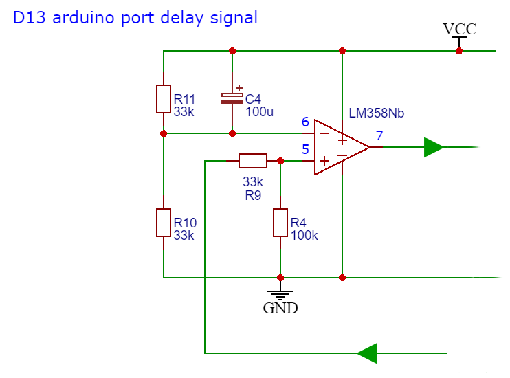
Port 4 DSLR activation and Arduino port D13 delay
Since I was left with very few free ports due to the touch screen, I had to use port D13 to activate output 4 (DSLR camera activation). The problem with the D13 port is that when we turn on the Arduino, it sends three pulses that trigger the output 4 port (DSLR). I tried to solve it with software but I didn't succeed. Since the IC LM384 is a dual OPA, I used the second OPA as a timer to delay the excitation response from port D13 to output 4. Capacitor C4 and divider R10-R11 determine the inactivity time of the circuit.
Port 4 DSLR activation and Arduino port D13 delay
Part list
Part list
Part list
Part list
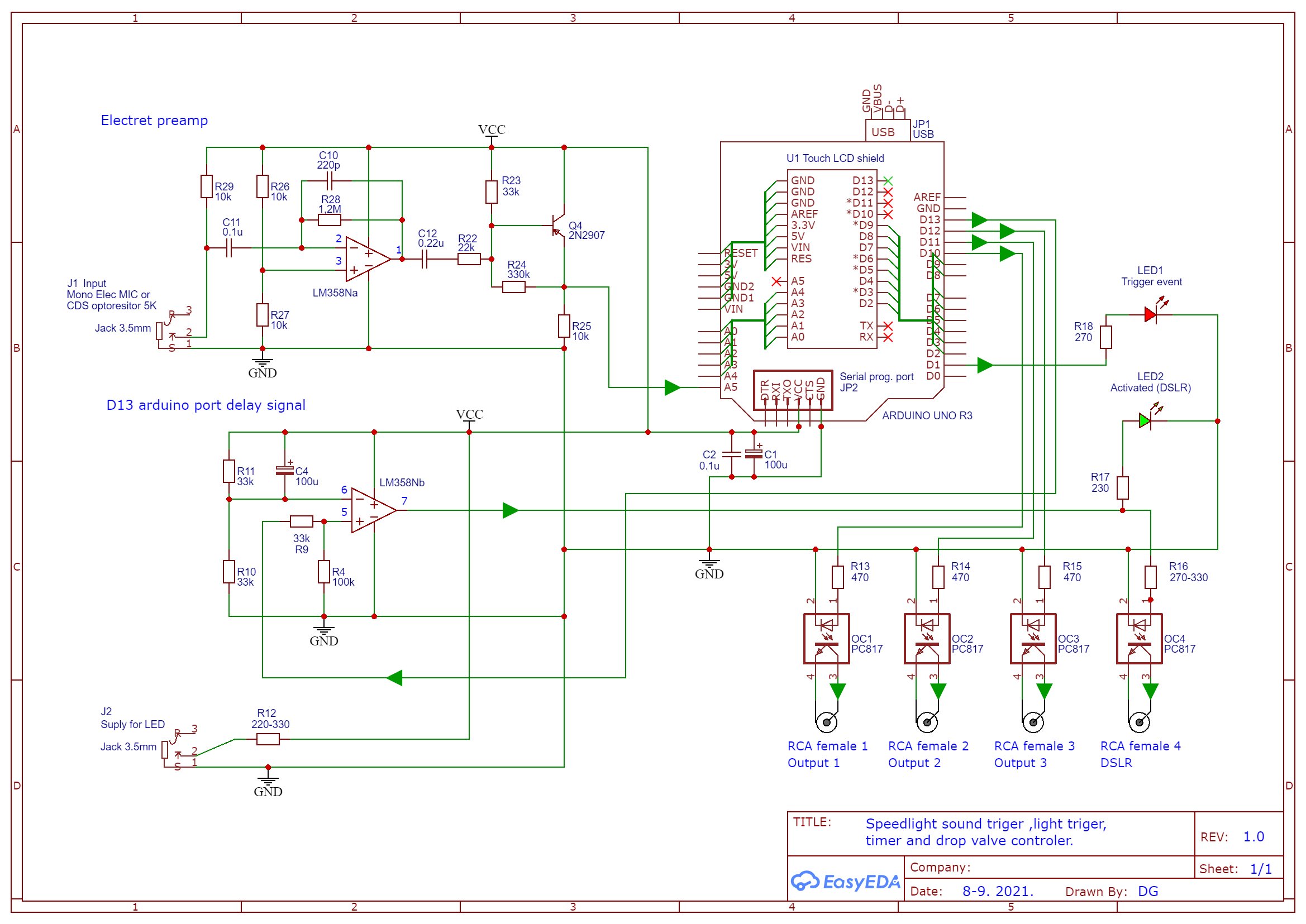
Schema
Schema
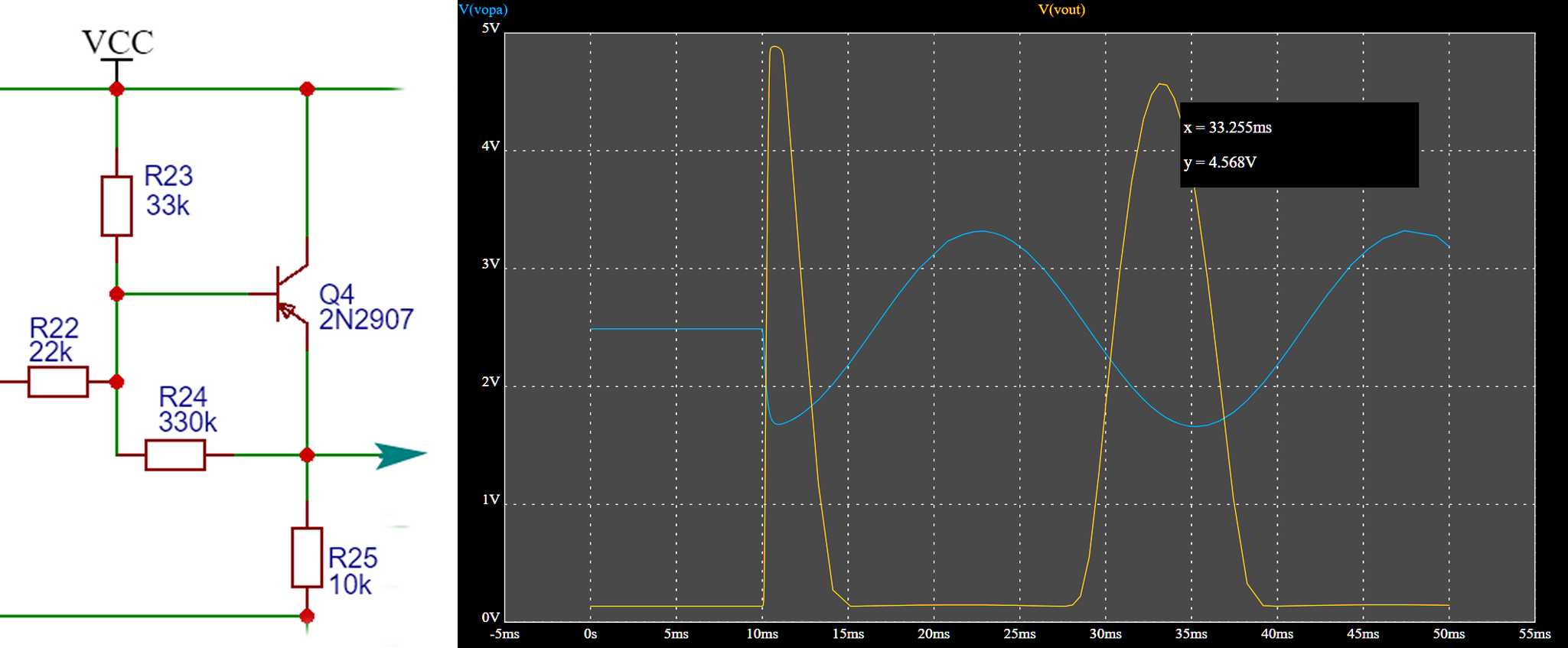
Positive amplitude amplifier
The output voltage from the preamp varies from 1.5 to 3.5 V approx., and the positive amplitude only from 2.5 to 3.5 V. The Arduino analog input accepts a positive voltage of 0 to 5 V at a resolution of 10 bits (1024 levels), so a resolution of positive amplitude (2.5 to 3.5 V) would be only a fifth of the total resolution (205 levels). The circuit with the PNP transistor (in the real circuit I used BC108b with 240 hfE) amplifies only the negative amplitude and "lowers" inverted amplitude towards zero. In this way, the useful voltage range expands from 0.4 V to 4.6 V (we have 4.2V differences and a resolution of 860-880 levels). The gain and distortion of the output is achieved by changing the resistance R22 (in my case 22K) and selecting a transistor with higher or lower gain (in my case 240 hfE).
Positive amplitude amplifier
Positive amplitude amplifier
The output voltage from the preamp varies from 1.5 to 3.5 V approx., and the positive amplitude only from 2.5 to 3.5 V. The Arduino analog input accepts a positive voltage of 0 to 5 V at a resolution of 10 bits (1024 levels), so a resolution of positive amplitude (2.5 to 3.5 V) would be only a fifth of the total resolution (205 levels). The circuit with the PNP transistor (in the real circuit I used BC108b with 240 hfE) amplifies only the negative amplitude and "lowers" inverted amplitude towards zero. In this way, the useful voltage range expands from 0.4 V to 4.6 V (we have 4.2V differences and a resolution of 860-880 levels). The gain and distortion of the output is achieved by changing the resistance R22 (in my case 22K) and selecting a transistor with higher or lower gain (in my case 240 hfE).
Positive amplitude amplifier
Schema
Schema
Port 4 DSLR activation and Arduino port D13 delay
Since I was left with very few free ports due to the touch screen, I had to use port D13 to activate output 4 (DSLR camera activation). The problem with the D13 port is that when we turn on the Arduino, it sends three pulses that trigger the output 4 port (DSLR). I tried to solve it with software but I didn't succeed. Since the IC LM384 is a dual OPA, I used the second OPA as a timer to delay the excitation response from port D13 to output 4. Capacitor C4 and divider R10-R11 determine the inactivity time of the circuit.
Port 4 DSLR activation and Arduino port D13 delay
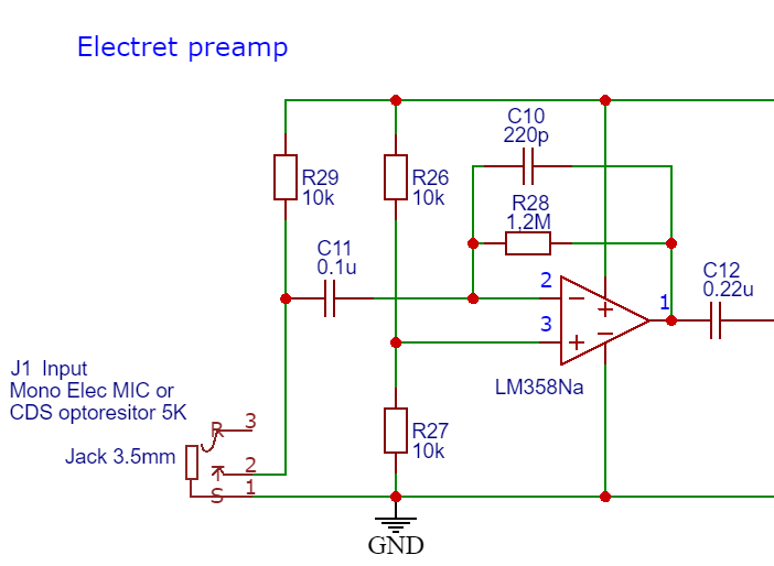
Preampifier
Preamplifier are made around OPA LM358 that operate as inverting operational amplifier. The gain of the preamplifier is given by resistor R28, and the best value is from 1M to 1.2 Mohm
Preampifier
Documentation
Lower part of the box (with connections)
Lower part of the box (with connections)
Lid with screen opening
Lid with screen opening
Lower part of the box (with connections)
Lower part of the box (with connections)
Lid with screen opening
Lid with screen opening
Comments
Only logged in users can leave comments