Devices & Components
Arduino Uno Rev3
LED (generic)
Pushbutton Switch, Momentary
Resistor 1k ohm
Hardware & Tools
ATmega328P data sheet
Project description
Code
Sync'd LEDs using timer and pin change interrupts.
arduino
A demonstration sketch for setting up interrupts on the ATmega328.
1/* 2 * Flash an LED two different ways. One with delay() and one with timer interrupts. 3 * The interrupt driven LED is kept in sync using pin change interrupts. 4 */ 5 6#define LED 9 7#define BUTTON 7 8 9void setup() { 10 Serial.begin(9600); 11 pinMode(LED_BUILTIN, OUTPUT); 12 digitalWrite(LED_BUILTIN, HIGH); 13 pinMode(LED, OUTPUT); 14 pinMode(BUTTON, INPUT_PULLUP); 15 16 // Disable interrupts while things are being set up. 17 cli(); 18 19 // Set up Timer/Counter Control Registers. See ATmega328P data sheet section 15.11 (Remember, bits are numbered from zero.) 20 TCCR1A = B00000000; // All bits zero for "normal" port operation. 21 TCCR1B = B00001100; // Bit 3 is Clear Timer on Compare match (CTC) and bit 2 specifies a divide by 256 prescaler. 22 TIMSK1 = B00000010; // Bit 1 to raise an interrupt on timer Output Compare Register A (OCR1A) match. 23 OCR1A = 62500; // Counter compare match value. 16MHz / prescaler * delay time (in seconds.) 24 25 // Set up Pin Change Interrupt Control Registers to detect incoming transitions. 26 PCICR = B00000100; // Enable only PCINT2 (PCINT23..16 or Arduino pins D0..D7). 27 PCMSK2 = B10000000; // Enable only INT23 (Arduino D7 pin). 28 29 // Reenable the interrupts 30 sei(); 31} 32 33void loop() { 34 digitalWrite(LED, LOW); 35 delay(1000); 36 digitalWrite(LED, HIGH); 37 delay(1000); 38} 39 40// Interrupt handler for timer match. 41ISR(TIMER1_COMPA_vect) 42{ 43 // Access pin 13 directly performing an XOR on Port B (digital pins 8 - 13). 44 // Same as "digitalWrite(LED_BUILTIN, !digitalRead(LED_BUILTIN))" 45 PORTB ^= B00100000; // Toggle bit 5, which maps to pin13. 46} 47 48// Interrupt handler for pin change. 49ISR(PCINT2_vect) 50{ 51 // To ensure the incoming bit is sampled in the middle for a more accurate reading, the timer counter 52 // should be at the middle of its maximum value when the pin change happens. The digital counter is 53 // extremely accurate, so speeding or slowing its frequency is not needed so much as simply ensuring 54 // the counter is at 1/2 its maximum value when the pin change interrupt occurs. 55 TCNT1 = OCR1A >> 1; 56}
Downloadable files
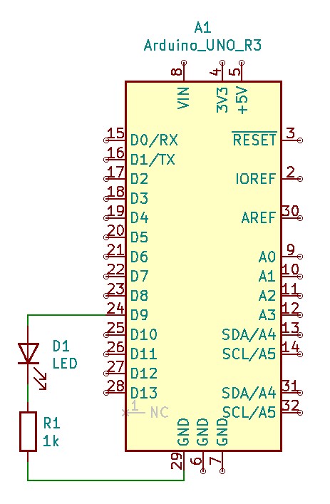
External LED
How to attach the external LED.
External LED
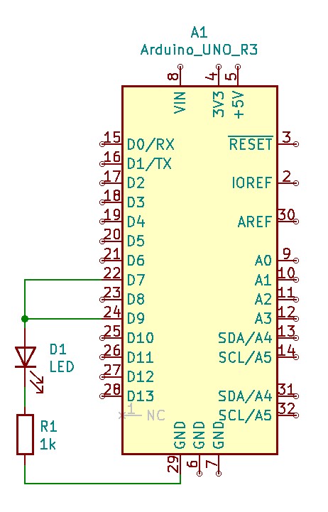
Self-Triggering Sync
Attaching output to input.
Self-Triggering Sync
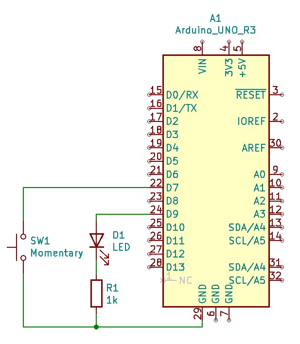
LED and Switch
Adding a momentary push-button switch.
LED and Switch
Self-Triggering Sync
Attaching output to input.
Self-Triggering Sync

External LED
How to attach the external LED.
External LED

LED and Switch
Adding a momentary push-button switch.
LED and Switch

Comments
Only logged in users can leave comments