Arduino CNC Mill Control Using ODrive Brushless DC Motors
CNC milling machine conversion using an Arduino Mega 2560 to control brushless DC motors powered by the ODrive motor controller.
Devices & Components
Arduino Mega 2560 Rev3
AMT102-V 8192 CPR Rotary Encoder
Displaytech 204A - 4 x 20 Line Blue & White LCD Display
Keypad, 3x4 Plastic - MCAK304NBWB
AD-13 Advanced Solderless Breadboard
Adafruit Mini 8x8 LED Matrix w/I2C Backpack - Ultra Bright White
ODrive Brushless DC Dual Shaft Motor - D5065 270KV
ODrive Brushless DC Motor Controller
Hardware & Tools
Axminter Sieg X1 Milling Machine
Software & Tools
Fusion 360
Alibre Design Professional
Project description
Code
Simple Arduino Joypad test Sketch
c_cpp
Please take a look at my video here for in-depth details: https://youtu.be/yI8ZIQ0cC4I
Downloadable files
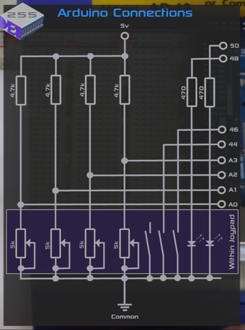
Simple Cirduit Diagram
This diagram shows the joypad and Arduino Mega 2560 connections in their simplest form.
Simple Cirduit Diagram
Simple Cirduit Diagram
This diagram shows the joypad and Arduino Mega 2560 connections in their simplest form.
Simple Cirduit Diagram
Comments
Only logged in users can leave comments