LED Lock Box
A lock box using a combination of 6 colors and 5 numbers in each combination "dial" - of which there are 3.
Components and supplies
1
Arduino Uno Rev3
1
5 mm LED: Green
4
Resistor 10k ohm
1
NeoPixel strip
2
Breadboard (generic)
1
5 mm LED: Red
2
Resistor 100 ohm
4
Pushbutton switch 12mm
3
Rotary potentiometer (generic)
Tools and machines
1
Laser cutter (generic)
Project description
Code
LED Lockbox code
arduino
1#include <Adafruit_NeoPixel.h>
2#ifdef __AVR__
3#include <avr/power.h>
4#endif
5#define   PIN 3
6Adafruit_NeoPixel strip = Adafruit_NeoPixel(15, PIN, NEO_GRB + NEO_KHZ800);
7
8int   aPot; // integer values for the potentiometer readings
9int bPot;
10int cPot;
11
12int   aPos; // integer values for the placement of each light, corresponding to an array   of lights
13int bPos;
14int cPos;
15
16uint32_t aColor = strip.Color(25, 0,   0); // this defines the color of the lights. We start with RGB, but it can be changed   if the user wants to start the board with different lights, just make sure to adjust
17uint32_t   bColor = strip.Color(0, 25, 0);        // the counters in rows 29-31 to reflect   each color, so red = 1, green = 2, blue = 3, yellow = 4, purple = 5, teal = 6
18uint32_t   cColor = strip.Color(0, 0, 25);
19
20uint32_t aKey = strip.Color(25, 0, 0); //   this defines the correct colors for each row of lights to unlock the box
21uint32_t   bKey = strip.Color(0, 25, 0);
22uint32_t cKey = strip.Color(0, 0, 25);
23
24int   aNumKey = 4; // each number here will be one less than the number on the console,   so 4 is the max.
25int bNumKey = 2; // these are the correct number values for   the light positions for each row. You must get the proper position and color for   each light to unlock the box
26int cNumKey = 3;
27
28int aCounter = 1;  // the   value for the color number you are on. 1 is red, 2 is green, 3 - blue, 4 - yellow,   5 - purple, 6 - teal
29int bCounter = 2;
30int cCounter = 3;
31
32void setup()   {
33  pinMode(13, INPUT); // define pins as inputs for buttons
34  pinMode(12,   INPUT);
35  pinMode(8, INPUT);
36  pinMode(7, INPUT);
37  Serial.begin(9600);
38   strip.begin(); // start the strip colors
39}
40
41void loop() {
42
43  aPot   = analogRead(A2); // read analog pins and assign them to potentiometer values
44   bPot = analogRead(A1);
45  cPot = analogRead(A0);
46  if (digitalRead(8) ==   HIGH) {         // if the first button, or button A, is pressed,
47    aColor   = setColor(8, aCounter);     // our color for aColor is set using our setColor function,   using the pin, 8, and aCounter, our counter for which color is currently selected
48     if (aCounter != 6) {  // if aCounter is not 6, we increment the counter
49       aCounter++; // This will increment the counter from whatever it is to one   higher. This way, when we get in a value of 0 from our setColor function, this will   set it to 1.
50    }
51    else {                // if it is 6, we need to re-set   it to 1, because we do not want the light to roll over into the next light
52      aCounter   = 1;
53    }
54  }
55  if (digitalRead(12) == HIGH) { // same but for button   attached to 12 pin (b button)
56    bColor = setColor(12, bCounter);
57    if   (bCounter != 6) {
58      bCounter++;
59    }
60    else {
61      bCounter   = 1;
62    }
63  }
64  if (digitalRead(13) == HIGH) {// same but for button   attached to 13 pin (c button)
65    cColor = setColor(13, cCounter);
66    if   (cCounter != 6) {
67      cCounter++;
68    }
69    else {
70      cCounter   = 1;
71    }
72  }
73  aPos = map(aPot, 0, 1030, 0, 5); // Map a position integer   to be the same as the potentiometer readings mapped from 0 to 5, because of how   the potentiometer reads, we can never get to 5, so it will give 5 values (0-4)
74   bPos = map(bPot, 0, 1030, 0, 5) + 5; // same for b position and c position
75   cPos = map(cPot, 0, 1030, 0, 5) + 10;
76
77  setPosition(aPos, aColor, 0,   5); // Set the position of the first light
78  setPosition(bPos, bColor, 5, 10);   // set position of the second light
79  setPosition(cPos, cColor, 10, 15); // set   position of the third light
80
81  if (digitalRead(7) == HIGH && aColor == aKey   && bColor == bKey && cColor == cKey && aPos == aNumKey && (bPos -5) == bNumKey &&   (cPos - 10) == cNumKey) { // turns on the Green LED if the code is correct
82    digitalWrite(4,   HIGH); // Turn on the Green LED
83    digitalWrite(2, LOW); // Turn off the Red   LED
84  }
85  else if(digitalRead(7) == HIGH && aColor != aKey || bColor != bKey   || cColor != cKey || aPos != aNumKey || (bPos - 5) != bNumKey || (cPos - 10) !=   cNumKey){ // Turns on the Red LED if the code is incorrect
86    digitalWrite(4,   LOW); // Turn off the Green LED
87    digitalWrite(2, HIGH); // Turn on the Red   LED
88  }
89
90}
91
92void setPosition(int potPosition, uint32_t stripColor,   int startIndex, int endIndex) { // takes in the reading for the positon of the potentiometer,   the color, start index for the row of lights, and the end index for the lights
93   strip.setPixelColor(potPosition, stripColor); // set the position read by the   potentiometer (which will be mapped to 0 through 4), to the color specified in parameters.   The color of the light is changed in setColor
94  for (int i = startIndex; i <   endIndex; i++) { // sort through the rest of the lights in that row
95    if (i   != potPosition) {                     // as long as those lights are not in the   same position as the light we just changed...
96      strip.setPixelColor(i, strip.Color(0,   0, 0)); // turn them off.
97    }
98  }
99  strip.show(); // display our new   configuration
100}
101uint32_t setColor(int pinNum, int counter) { // takes in values   for what pin number the function will be reading from, and the counter value of   that current color. Each color correlates to a number from 0-5 (6 colors)
102  uint32_t   color;
103  if (digitalRead(pinNum) == HIGH) { // for a function, parameters need   to be pin number, counter for that button, and color for that pin
104    if (counter   == 1) {
105      color = strip.Color(0, 25, 0);
106    }
107    if (counter == 2)   {
108      color = strip.Color(0, 0, 25);
109    }
110    if (counter == 3) {
111       color = strip.Color(25, 25, 0);
112    }
113    if (counter == 4) {
114      color   = strip.Color(25, 0, 25);
115    }
116    if (counter == 5) {
117      color = strip.Color(0,   25, 25);
118    }
119    if (counter == 6) {
120      counter = 0;              //   this is set to 0, because our value will be incremented outside of this function.   For example, line 50 increments this color from 0 to 1.
121      color = strip.Color(25,   0, 0);
122    }
123    delay(150); // This makes sure that we can delay for a bit   to let the button be released.
124  }
125  return color;
126}
127
LED Lockbox code
arduino
1#include <Adafruit_NeoPixel.h>
2#ifdef __AVR__
3#include <avr/power.h>
4#endif
5#define  PIN 3
6Adafruit_NeoPixel strip = Adafruit_NeoPixel(15, PIN, NEO_GRB + NEO_KHZ800);
7
8int  aPot; // integer values for the potentiometer readings
9int bPot;
10int cPot;
11
12int  aPos; // integer values for the placement of each light, corresponding to an array  of lights
13int bPos;
14int cPos;
15
16uint32_t aColor = strip.Color(25, 0,  0); // this defines the color of the lights. We start with RGB, but it can be changed  if the user wants to start the board with different lights, just make sure to adjust
17uint32_t  bColor = strip.Color(0, 25, 0);        // the counters in rows 29-31 to reflect  each color, so red = 1, green = 2, blue = 3, yellow = 4, purple = 5, teal = 6
18uint32_t  cColor = strip.Color(0, 0, 25);
19
20uint32_t aKey = strip.Color(25, 0, 0); //  this defines the correct colors for each row of lights to unlock the box
21uint32_t  bKey = strip.Color(0, 25, 0);
22uint32_t cKey = strip.Color(0, 0, 25);
23
24int  aNumKey = 4; // each number here will be one less than the number on the console,  so 4 is the max.
25int bNumKey = 2; // these are the correct number values for  the light positions for each row. You must get the proper position and color for  each light to unlock the box
26int cNumKey = 3;
27
28int aCounter = 1;  // the  value for the color number you are on. 1 is red, 2 is green, 3 - blue, 4 - yellow,  5 - purple, 6 - teal
29int bCounter = 2;
30int cCounter = 3;
31
32void setup()  {
33  pinMode(13, INPUT); // define pins as inputs for buttons
34  pinMode(12,  INPUT);
35  pinMode(8, INPUT);
36  pinMode(7, INPUT);
37  Serial.begin(9600);
38  strip.begin(); // start the strip colors
39}
40
41void loop() {
42
43  aPot  = analogRead(A2); // read analog pins and assign them to potentiometer values
44  bPot = analogRead(A1);
45  cPot = analogRead(A0);
46  if (digitalRead(8) ==  HIGH) {         // if the first button, or button A, is pressed,
47    aColor  = setColor(8, aCounter);     // our color for aColor is set using our setColor function,  using the pin, 8, and aCounter, our counter for which color is currently selected
48    if (aCounter != 6) {  // if aCounter is not 6, we increment the counter
49      aCounter++; // This will increment the counter from whatever it is to one  higher. This way, when we get in a value of 0 from our setColor function, this will  set it to 1.
50    }
51    else {                // if it is 6, we need to re-set  it to 1, because we do not want the light to roll over into the next light
52      aCounter  = 1;
53    }
54  }
55  if (digitalRead(12) == HIGH) { // same but for button  attached to 12 pin (b button)
56    bColor = setColor(12, bCounter);
57    if  (bCounter != 6) {
58      bCounter++;
59    }
60    else {
61      bCounter  = 1;
62    }
63  }
64  if (digitalRead(13) == HIGH) {// same but for button  attached to 13 pin (c button)
65    cColor = setColor(13, cCounter);
66    if  (cCounter != 6) {
67      cCounter++;
68    }
69    else {
70      cCounter  = 1;
71    }
72  }
73  aPos = map(aPot, 0, 1030, 0, 5); // Map a position integer  to be the same as the potentiometer readings mapped from 0 to 5, because of how  the potentiometer reads, we can never get to 5, so it will give 5 values (0-4)
74  bPos = map(bPot, 0, 1030, 0, 5) + 5; // same for b position and c position
75  cPos = map(cPot, 0, 1030, 0, 5) + 10;
76
77  setPosition(aPos, aColor, 0,  5); // Set the position of the first light
78  setPosition(bPos, bColor, 5, 10);  // set position of the second light
79  setPosition(cPos, cColor, 10, 15); // set  position of the third light
80
81  if (digitalRead(7) == HIGH && aColor == aKey  && bColor == bKey && cColor == cKey && aPos == aNumKey && (bPos -5) == bNumKey &&  (cPos - 10) == cNumKey) { // turns on the Green LED if the code is correct
82    digitalWrite(4,  HIGH); // Turn on the Green LED
83    digitalWrite(2, LOW); // Turn off the Red  LED
84  }
85  else if(digitalRead(7) == HIGH && aColor != aKey || bColor != bKey  || cColor != cKey || aPos != aNumKey || (bPos - 5) != bNumKey || (cPos - 10) !=  cNumKey){ // Turns on the Red LED if the code is incorrect
86    digitalWrite(4,  LOW); // Turn off the Green LED
87    digitalWrite(2, HIGH); // Turn on the Red  LED
88  }
89
90}
91
92void setPosition(int potPosition, uint32_t stripColor,  int startIndex, int endIndex) { // takes in the reading for the positon of the potentiometer,  the color, start index for the row of lights, and the end index for the lights
93  strip.setPixelColor(potPosition, stripColor); // set the position read by the  potentiometer (which will be mapped to 0 through 4), to the color specified in parameters.  The color of the light is changed in setColor
94  for (int i = startIndex; i <  endIndex; i++) { // sort through the rest of the lights in that row
95    if (i  != potPosition) {                     // as long as those lights are not in the  same position as the light we just changed...
96      strip.setPixelColor(i, strip.Color(0,  0, 0)); // turn them off.
97    }
98  }
99  strip.show(); // display our new  configuration
100}
101uint32_t setColor(int pinNum, int counter) { // takes in values  for what pin number the function will be reading from, and the counter value of  that current color. Each color correlates to a number from 0-5 (6 colors)
102  uint32_t  color;
103  if (digitalRead(pinNum) == HIGH) { // for a function, parameters need  to be pin number, counter for that button, and color for that pin
104    if (counter  == 1) {
105      color = strip.Color(0, 25, 0);
106    }
107    if (counter == 2)  {
108      color = strip.Color(0, 0, 25);
109    }
110    if (counter == 3) {
111      color = strip.Color(25, 25, 0);
112    }
113    if (counter == 4) {
114      color  = strip.Color(25, 0, 25);
115    }
116    if (counter == 5) {
117      color = strip.Color(0,  25, 25);
118    }
119    if (counter == 6) {
120      counter = 0;              //  this is set to 0, because our value will be incremented outside of this function.  For example, line 50 increments this color from 0 to 1.
121      color = strip.Color(25,  0, 0);
122    }
123    delay(150); // This makes sure that we can delay for a bit  to let the button be released.
124  }
125  return color;
126}
127
Downloadable files
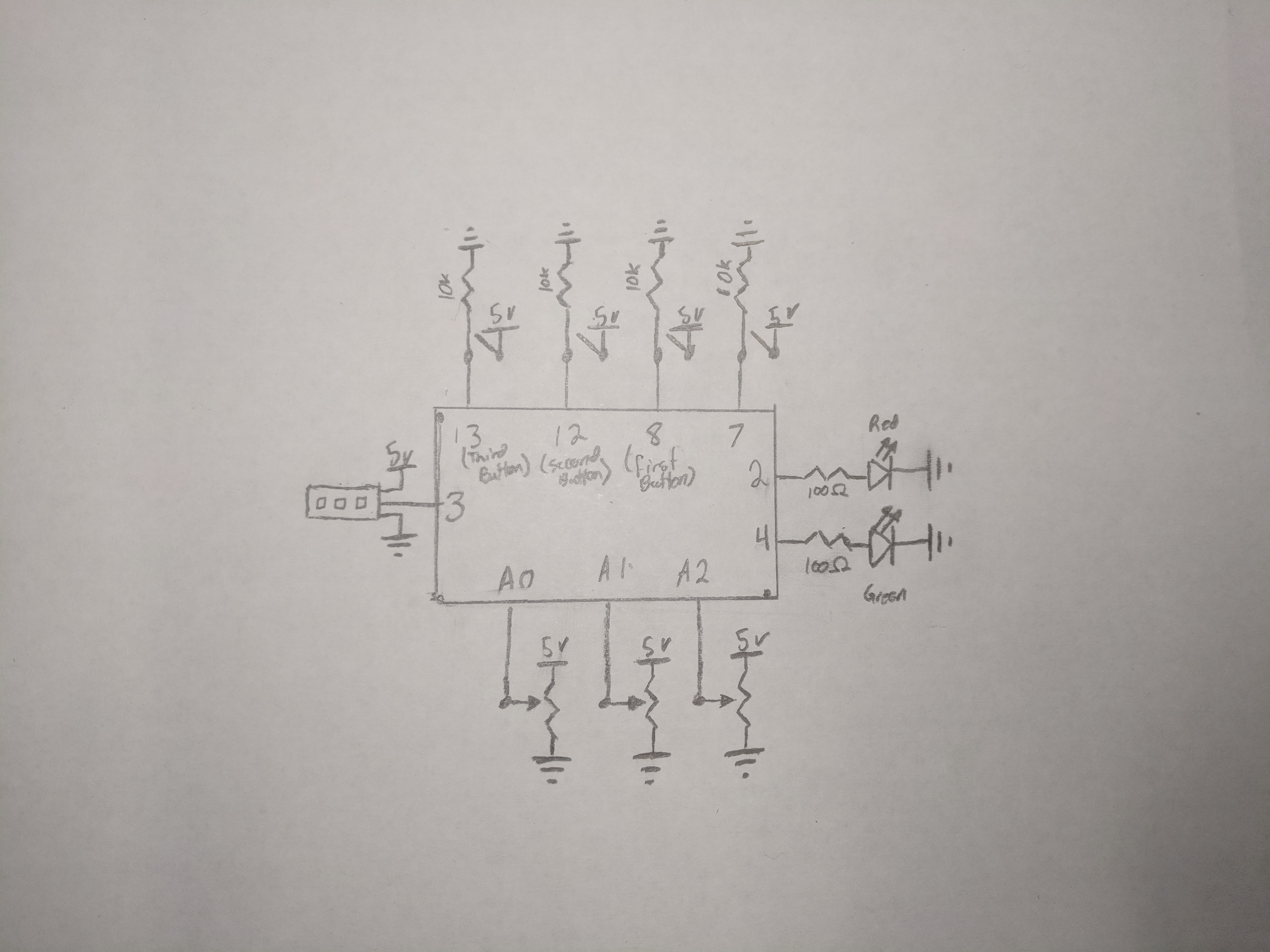
LED Lockbox circuit diagram
LED Lockbox circuit diagram
Comments
Only logged in users can leave comments