Marker Beacon System with IR Sensors, Buzzer and LED
Three marker beacon station (IR Sensors) are on the ground and detecting the aircraft is approaching the runway passing over the Markers.
Devices & Components
Arduino Uno Rev3
Breadboard (generic)
IR Proximity Sensor
Speaker, Micro
5 mm LED: Red
Hardware & Tools
Plier, Long Nose
Multitool, Screwdriver
Software & Tools
Arduino IDE
Project description
Code
Source Code For Marker Beacon System
c_cpp
Downloadable files
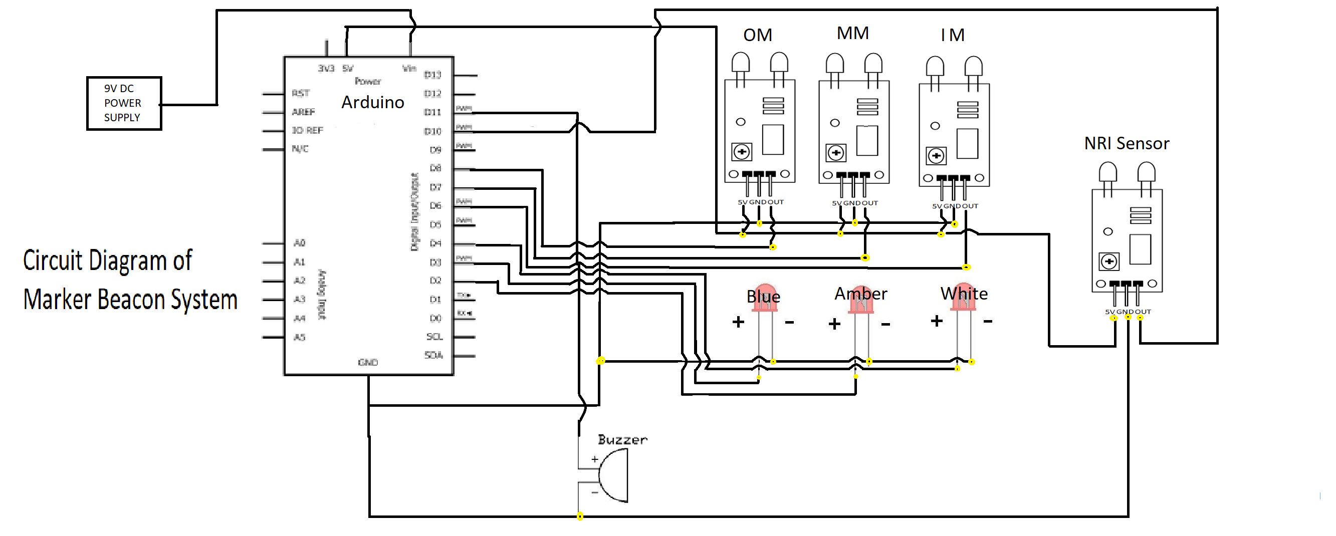
Circuit Diagram
A) IR Proximity sensor connections: 1. Connect OUT of inner marker (Sensor) to Arduino's digital pin 6. 2. Then connect the OUT of middle marker (Sensor) to Arduino's digital pin 7. 3. Same as inner and middle connect the OUT of outer marker (Sensor) to Arduino's digital pin 8 4. Then connect OUT of NRI (No Return Indication sensor) to Arduino's digital pin 10. 5. Connect the GRD i.e. (ground) of all sensors to Arduino's pin ground. 6. Connect VCC of all sensors to Arduino's pin of +5 V. B) LED's connections: 1. Connect +ve terminal of inner marker (LED) to arduino's digital pin 4. 2. Then connect the +ve terminal of middle marker (LED) to Arduino's digital pin 2. 3. Connect the +ve of outer marker (LED) to Arduino's digital pin 3. 4. After that connect all the -ve outer marker (LED) to Arduino's pin ground. C) Buzzer connection: 1. Connect one terminal to Arduino's digital pin 11. 1. Connect another terminal to arduino's Pin GRD. Circuit diagram stanltjx1s
Circuit Diagram
Circuit Diagram
A) IR Proximity sensor connections: 1. Connect OUT of inner marker (Sensor) to Arduino's digital pin 6. 2. Then connect the OUT of middle marker (Sensor) to Arduino's digital pin 7. 3. Same as inner and middle connect the OUT of outer marker (Sensor) to Arduino's digital pin 8 4. Then connect OUT of NRI (No Return Indication sensor) to Arduino's digital pin 10. 5. Connect the GRD i.e. (ground) of all sensors to Arduino's pin ground. 6. Connect VCC of all sensors to Arduino's pin of +5 V. B) LED's connections: 1. Connect +ve terminal of inner marker (LED) to arduino's digital pin 4. 2. Then connect the +ve terminal of middle marker (LED) to Arduino's digital pin 2. 3. Connect the +ve of outer marker (LED) to Arduino's digital pin 3. 4. After that connect all the -ve outer marker (LED) to Arduino's pin ground. C) Buzzer connection: 1. Connect one terminal to Arduino's digital pin 11. 1. Connect another terminal to arduino's Pin GRD. Circuit diagram stanltjx1s
Circuit Diagram
Documentation
Block Diagram
Block Diagram
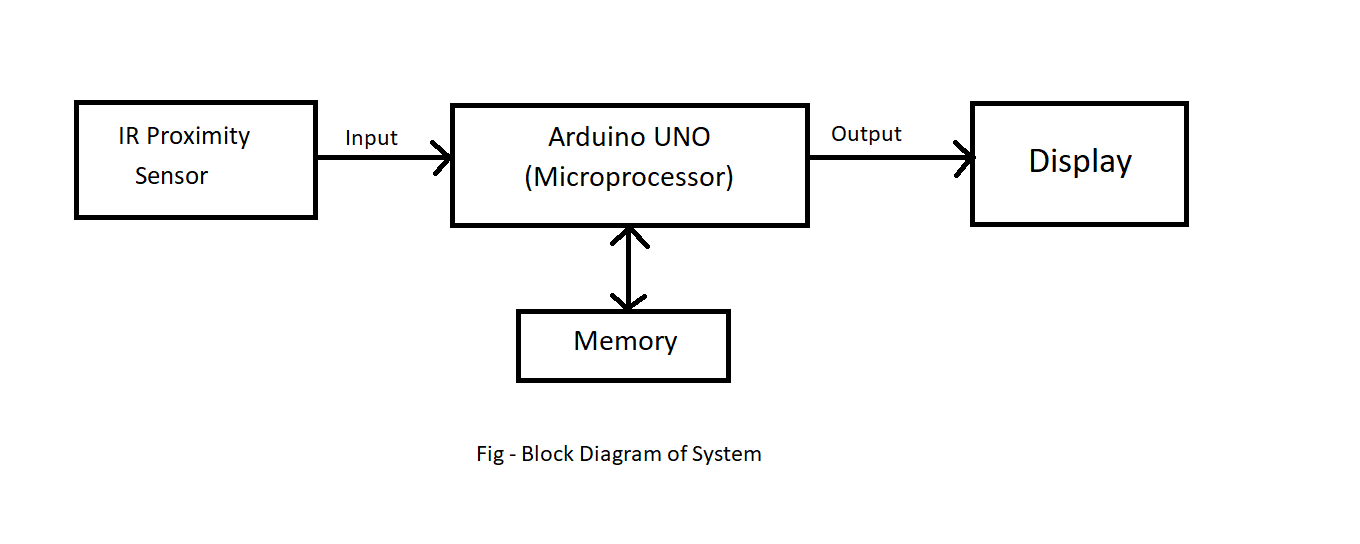
Block Diagram
Block Diagram
Comments
Only logged in users can leave comments