Devices & Components
1
Arduino Uno Rev3
11
Jumper wires (generic)
1
Solderless Breadboard Full Size
10
Resistor 330 ohm
Project description
Code
Flash_Bright_Beginner_code
arduino
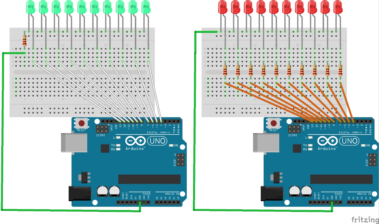
There are two circuits to see and the code shows how everything works.
1/* Flash BRIGHT = Larsen scanner/Knight Rider easy-learner coding.
2                 By Neil Doherty 09/2019
3 First, the Arduino Editor does not  load these notes onto a board,
4it only loads the operating code.
5 Pins are  where you push jumper wires into.
6*/
7
8int LED3 = 3;   // Each Arduino  pin has a number or name.
9int LED4 = 4;   // Here,a value is assigned to the  pins
10int LED5 = 5;   // numbered 3 to 12, using int (integer).
11int LED6 =  6;   // A jumper-wire connects each Arduino pin
12int LED7 = 7;   // to the positive/long  leg of an LED
13int LED8 = 8;   // (L-ight E-mitting D-iode) on a 'breadboard'.
14int  LED9 = 9;   // As it's name implies, an actual breadboard
15int LED10 = 10; //  was first used to tap pins into and wires
16int LED11 = 11; // strung between,  making connections.
17int LED12 = 12;
18
19const int DELAY = 50; // const int  uses less memory than int.
20                      // For this circuit all of them  could use
21                      // const int, but it illustrates both uses.
22                      // The main difference is that with int,
23                      //  you can change the value inside the loop
24                      // function which  you will come to learn can
25                      // be very useful, whereas  const int cannot
26                      // be changed.
27void setup() {
28
29
30  pinMode(LED3, OUTPUT); // pinMode is a command to the Arduino
31  pinMode(LED4,  OUTPUT); // to apply what is in the brackets.
32  pinMode(LED5, OUTPUT); // < in  this case, (LED5,set to transmit)
33  pinMode(LED6, OUTPUT); // And so on for the  others.
34  pinMode(LED7, OUTPUT); // INPUT only applies to certain pins when
35  pinMode(LED8, OUTPUT); // used.
36  pinMode(LED9, OUTPUT);
37  pinMode(LED10,  OUTPUT);
38  pinMode(LED11, OUTPUT);
39  pinMode(LED12, OUTPUT);
40
41
42  digitalWrite(12,  LOW); // These commands switch all the LEDs
43  digitalWrite(11, LOW); // to no  power out. LOW meaning OFF
44  digitalWrite(10, LOW); // HIGH meaning ON
45  digitalWrite(9,  LOW);  // These lines make sure ALL LEDs are
46  digitalWrite(8, LOW);  // off  to begin with.
47  digitalWrite(7, LOW);
48  digitalWrite(6, LOW);
49  digitalWrite(5,  LOW);
50  digitalWrite(4, LOW);
51  digitalWrite(3, LOW);
52
53}
54
55void  loop() {
56  //Forward
57  digitalWrite(12, HIGH); // Switch LED attached to pin  12 on
58  delay(DELAY);           // allowing the LED to light up HIGH
59  digitalWrite(12,  LOW);  // for a period of DELAY = 50
60  delay(DELAY);           // microseconds  = 50m, where 1000m is 1 second.
61  digitalWrite(11, HIGH); // Then it is switched  LOW for the next 50m
62  delay(DELAY);
63  digitalWrite(11, LOW);  // This section  lights the LEDs in one direction
64  delay(DELAY);
65  digitalWrite(10, HIGH);  // digitalwrite just says 'let there be light'
66  delay(DELAY);           // well,  only for the relevant LED, that is.
67  digitalWrite(10, LOW);  // It instructs  the Arduino to make the power
68  delay(DELAY);           // to the pin ON/HIGH  or OFF/LOW.
69  digitalWrite(9, HIGH);
70  delay(DELAY);
71  digitalWrite(9,  LOW);
72  delay(DELAY);
73  digitalWrite(8, HIGH);
74  delay(DELAY);
75  digitalWrite(8,  LOW);
76  delay(DELAY);
77  digitalWrite(7, HIGH);
78  delay(DELAY);
79  digitalWrite(7,  LOW);
80  delay(DELAY);
81  digitalWrite(6, HIGH);
82  delay(DELAY);
83  digitalWrite(6,  LOW);
84  delay(DELAY);
85  digitalWrite(5, HIGH);
86  delay(DELAY);
87  digitalWrite(5,  LOW);
88  delay(DELAY);
89  digitalWrite(4, HIGH);
90  delay(DELAY);
91  digitalWrite(4,  LOW);
92  delay(DELAY);
93  digitalWrite(3, HIGH);
94  delay(DELAY);
95  digitalWrite(3,  LOW);
96  delay(DELAY);
97
98  // NOW Reverse
99
100  digitalWrite(4, LOW);  // This section makes the LEDs light up
101  delay(DELAY);          // in the  other direction.
102  digitalWrite(5, HIGH);
103  delay(DELAY);
104  digitalWrite(5,  LOW);  // You might notice, and wonder, why this
105  delay(DELAY);          //  section has neither 3 nor 12 pins repeated.
106  delay(DELAY);          // That  is because it would cause the two end
107  digitalWrite(6, LOW);  // LEDs to double-flash,  which would look strange
108  delay(DELAY);          // To be sure, add them in,  upload again and
109  digitalWrite(7, HIGH); // see it happen.
110  delay(DELAY);
111  digitalWrite(7, LOW);  // Experiment by changing
112  delay(DELAY);
113  digitalWrite(8,  HIGH);
114  delay(DELAY);
115  digitalWrite(8, LOW);
116  delay(DELAY);
117  digitalWrite(9,  HIGH);
118  delay(DELAY);
119  digitalWrite(9, LOW);
120  delay(DELAY);
121  digitalWrite(10,  HIGH);
122  delay(DELAY);
123  digitalWrite(10, LOW);
124  delay(DELAY);
125  digitalWrite(11,  HIGH);
126  delay(DELAY);
127  digitalWrite(11, LOW);
128  delay(DELAY);
129
130}
Downloadable files
Comparison Knight Rider circuits
Super-beginner programming.
Comparison Knight Rider circuits
Comparison Knight Rider circuits
Super-beginner programming.
Comparison Knight Rider circuits
Comments
Only logged in users can leave comments