Devices & Components
Arduino Uno Rev3
Jumper wires (generic)
Pushbutton Switch, Momentary
LED (generic)
Solderless Breadboard Half Size
Resistor 220 ohm
Project description
Code
GREEN_or_RED_Button
arduino
Copied and pasted to make two separate programs for two simultaneously PC-connected, independently programmable Arduinos.
1/* GREEN or RED LED-Arduino. Copy and paste the 2code into each program connected to a different 3Arduino, giving one the name GREEN_LED and the 4other RED_LED. 5The basic code and the circuit setup is public 6domain but taken from Massimo Banzi's book, 7"Getting Started with Arduino". In his version, 8the LED is plugged into 13 and GND, next to it, 9on the Arduino board - and you can use that 10method if you prefer. I extended this onto the 11breadboard, the colour-coding is easily visible. 12*/ 13 14const int LED = 13; /* "const int" because uses 15less memory and does not change */ 16const int BUTTON = 7; // Pin 7 for LED test 17 // = ON or OFF 18int val = 0; // val stores the button state 19int old_val = 0; // stores the old val-ue 20int state = 0; // 0 sets LED OFF 1 sets LED ON 21 22void setup() { 23 pinMode(LED, OUTPUT); // Defines Pin 13 as output 24 pinMode(BUTTON, INPUT); // BUTTON is an input to 25 //record when pressed. 26} 27 28void loop() { 29val = digitalRead(BUTTON); // read and store the LED 30 //state is it HIGH? Maybe 31 //change state. 32if ((val == HIGH) && (old_val == LOW)){ 33 state = 1 - state; 34 delay(10); 35} 36old_val = val; // 37if (state == 1) { 38 digitalWrite(LED, HIGH); // turn LED on 39} else { 40 digitalWrite(LED, LOW); 41} 42}
GREEN_or_RED_Button
arduino
Copied and pasted to make two separate programs for two simultaneously PC-connected, independently programmable Arduinos.
1/* GREEN or RED LED-Arduino. Copy and paste the 2code into each program 3 connected to a different 4Arduino, giving one the name GREEN_LED and the 5other 6 RED_LED. 7The basic code and the circuit setup is public 8domain but taken 9 from Massimo Banzi's book, 10"Getting Started with Arduino". In his version, 11the 12 LED is plugged into 13 and GND, next to it, 13on the Arduino board - and you 14 can use that 15method if you prefer. I extended this onto the 16breadboard, 17 the colour-coding is easily visible. 18*/ 19 20const int LED = 13; /* "const 21 int" because uses 22less memory and does not change */ 23const int BUTTON = 24 7; // Pin 7 for LED test 25 // = ON or OFF 26int val = 0; 27 // val stores the button state 28int old_val = 0; // stores the old val-ue 29int 30 state = 0; // 0 sets LED OFF 1 sets LED ON 31 32void setup() { 33 pinMode(LED, 34 OUTPUT); // Defines Pin 13 as output 35 pinMode(BUTTON, INPUT); // BUTTON is an 36 input to 37 //record when pressed. 38} 39 40void loop() 41 { 42val = digitalRead(BUTTON); // read and store the LED 43 //state 44 is it HIGH? Maybe 45 //change state. 46if ((val == HIGH) 47 && (old_val == LOW)){ 48 state = 1 - state; 49 delay(10); 50} 51old_val 52 = val; // 53if (state == 1) { 54 digitalWrite(LED, HIGH); // turn LED on 55} 56 else { 57 digitalWrite(LED, LOW); 58} 59}
Downloadable files
Two Arduinos independent on one PC
It is a demonstration that you can connect multiple Arduinos to one PC AND independently program them. Basic image is Fritzing with added editing for clarity.
Two Arduinos independent on one PC
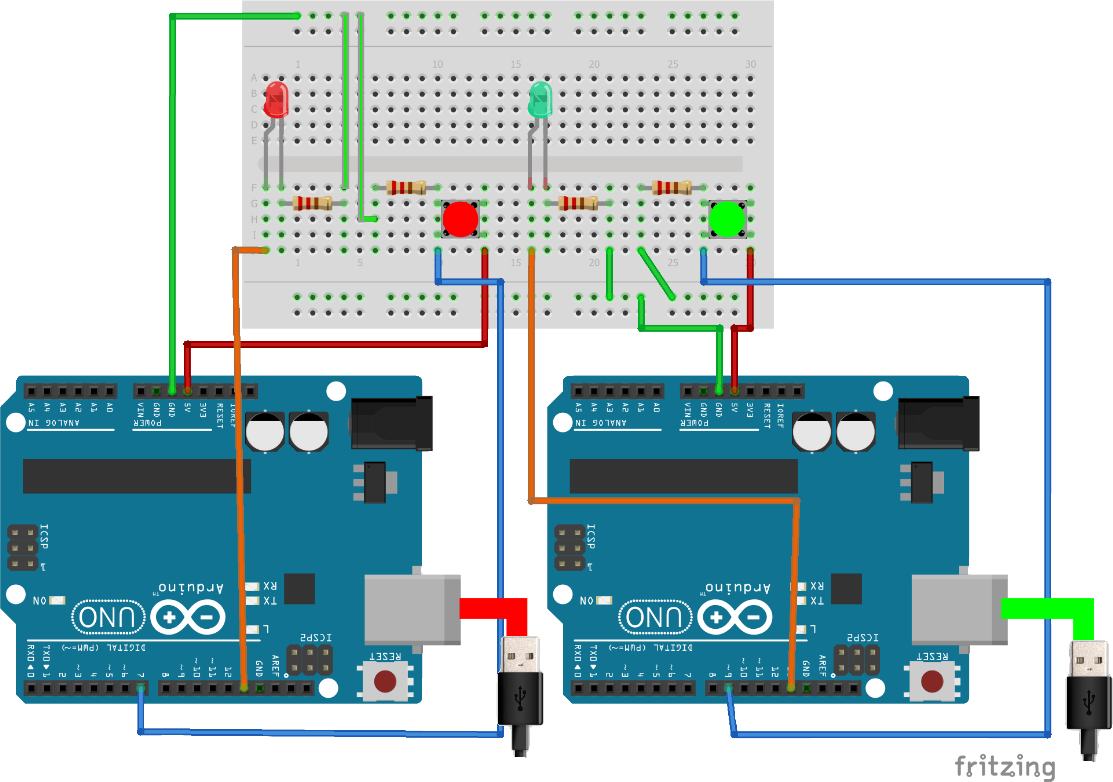
Two Arduinos independent on one PC
It is a demonstration that you can connect multiple Arduinos to one PC AND independently program them. Basic image is Fritzing with added editing for clarity.
Two Arduinos independent on one PC

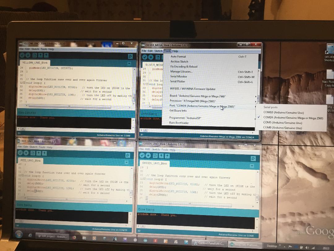
Proof four Arduinos attached.
Demonstrates that you can attached 4 Arduinos
Proof four Arduinos attached.
Comments
Only logged in users can leave comments