Mobile Fine Dust (PM10 & PM2.5) and NO2 Meter
This device measures fine dust and NO2 concentration in the air while on the move and adds GPS coordinates to each measurement location.
Devices & Components
Arduino Nano
Resistor 2.21k ohm
7-segment single digit
Resistor 1k ohm
Capacitor 100 nF
74LS138 3-to-8 line decoder TTL IC
Dual Pole Dual Throw (DPDT) Switch
555 Timers
Open Smart GPS-module
Resistor 33k ohm
General Purpose Transistor NPN
SDcard reader VMA304
NO2-sensor CJMCU-4541
General Purpose Transistor PNP
Single Turn Potentiometer- 100k ohms
Resistor 330 ohm
Capacitor 100 µF
3 mm LED: Red
DHT22 Temperature Sensor
Resistor 560 ohm
Fine dust sensor SDS011
74HC4511 BCD to Seven-Segment Decoder / Driver / Latch
Software & Tools
Google Maps
Project description
Code
Mobile fine dust and NO2 meter
arduino
This is the code for the mobile fine dust meter with the optional display and NO2 meter, but this code also works for the basic version without display and the NO2 meter. Mandatory modules are the SDS011 fine dust sensor, the DHT22 sensor for measuring humidity and temperature and the GPS-module, because these modules transmit their measurements over a serial interface and for each of these sensors a wait-loop is traversed to capture new serial data. Also mandatory is the SDcard interface (SPI) which takes care of the logging of the gathered data on a SDcard. Further, this code features the following functions: 1. Creation of a new logfile each time the meter is powered on. 2. Calculation of a hash code when writing a new data record to the logfile. 3. Creation of a digital signature using the hash code at power shutdown or too low supply voltage. 4. Monitoring of the supply voltage and giving a low battery warning on the display 5. Software controlled power down to finish ongoing write cycle to the SDcard and writing the signature. 6. Round-robin rotation through 4 display modes by toggling the DPDT power switch. 7. Showing 6 different error codes on the display: 001 SDcard initialization failed 002 No FAT partition found 003 Initialization file access failed 004 Low battery voltage 005 GPS signal unreliable 006 Cannot open the logfile
Downloadable files
Schematics of the main interconnection board
This board interconnects all components: Arduino Nano, OpenSmart GPS-module and SDcard reader are plugged directly onto the board. The sensors SDS011, DHT22 and GJMCU-4541 are connected via cables as well as the optional display board and the earphone connector for the external warning device. The board houses also the soft power off electronics, a timer to provide a 30 seconds preheating of the NO2-sensor and a LED indicating write cycles to the SDcard. Battery power and DPDT-switch are also connected to the main board.
Schematics of the main interconnection board
Schematics of the main interconnection board
This board interconnects all components: Arduino Nano, OpenSmart GPS-module and SDcard reader are plugged directly onto the board. The sensors SDS011, DHT22 and GJMCU-4541 are connected via cables as well as the optional display board and the earphone connector for the external warning device. The board houses also the soft power off electronics, a timer to provide a 30 seconds preheating of the NO2-sensor and a LED indicating write cycles to the SDcard. Battery power and DPDT-switch are also connected to the main board.
Schematics of the main interconnection board
Display Board
This is the optional display board, which comprises 2x3 7-segment digits to show the measurement results of the 5 sensor values in real time.
Display Board
Display Board
This is the optional display board, which comprises 2x3 7-segment digits to show the measurement results of the 5 sensor values in real time.
Display Board
Documentation
Mechanical drawing of main interconnection PCB
A printed circuit board has been developed on which all components can be soldered or connected by means of flat cables. The Arduino Nano microcontroller, SDcard, GPS-module and electronics to ensure soft power down are soldered onto this board. DHT-, NO2- and PM-sensors are connected to this board via flat cables.
Mechanical drawing of main interconnection PCB
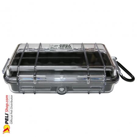
Transparant housing for mobile finedust meter
This is the housing in which all components will fit perfectly, including the display board and battery.
Transparant housing for mobile finedust meter
Mechanical drawing of main interconnection PCB
A printed circuit board has been developed on which all components can be soldered or connected by means of flat cables. The Arduino Nano microcontroller, SDcard, GPS-module and electronics to ensure soft power down are soldered onto this board. DHT-, NO2- and PM-sensors are connected to this board via flat cables.
Mechanical drawing of main interconnection PCB
Transparant housing for mobile finedust meter
This is the housing in which all components will fit perfectly, including the display board and battery.
Transparant housing for mobile finedust meter
Comments
Only logged in users can leave comments