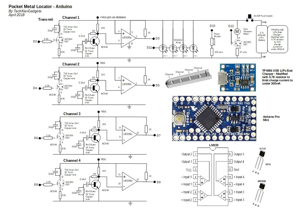
Pocket Metal Locator
Cool little Pocket Metal Locator sensitive enough to identify small nails and tacks in wood with four independent search coils and LEDs.
Components and supplies
Arduino Pro Mini 328 - 5V/16MHz
Tools and machines
3D Printer (generic)
Project description
Code
Pocket_Metal_Locator_V11.ino
c_cpp
This cool little Pocket Metal Locator is sensitive enough to identify small nails and tacks in wood and compact enough to fit into awkward spaces making it convenient to carry and use for metal locating. The unit has four independent search coils and color LED indicators making it easy to cover a larger search area quickly while being able to accurately identify the target. This neat little device is self-calibrating with one button operation, rechargeable through a USB port and uses color LEDs, sound and vibration to indicate target strength. Included in the instructable is all of the designs, testing, code and 3D files required to build on your own. I hope you enjoy building and using this as much as I have!!
1/* Pocket Metal Locator - Arduino Pro Mini April 2018 TechKiwiGradgets
2Version  11 - First Instructable Release
3
4*/
5
6// WS2182 LED Driver Library Setup
7#include  "FastLED.h"
8// How many leds in your strip?
9#define NUM_LEDS 4 // Note:  First LED is address 0
10#define DATA_PIN 11 // Note: D11 used to control LED chain
11
12//  Define the array of leds
13CRGB leds[NUM_LEDS];
14
15// Smoothing Variables for  LPF
16const float alpha = 0.85;
17float smoothedvalue1 = 1000;
18float smoothedvalue2  = 1000;
19float smoothedvalue3 = 1000;
20float smoothedvalue4 = 1000;
21
22int  sthreshold = 100; // Minimum reading from pulseIn function ensure sampling above  noise
23
24float ledthreshold1 = 0.93; // Percentage below baseline before setting  LEDs Purple
25float ledthreshold2 = 0.96; // Percentage below baseline before setting  LEDs Red
26float ledthreshold3 = 0.99; // Percentage below baseline before setting  LEDs Green
27float ledthreshold4 = 0.998; // Percentage below baseline before setting  LEDs Blue
28
29
30
31// Callibration Variables
32
33boolean sample = false;  // if true then do not recallibrate thresholds
34int calcounter = 0; // Used to  count the number of times a sample has been taken
35int scount = 200; // Number  of reads before calibrating once only after power up
36int numsamples = 20; //  Number of samples taken before averaging them
37int t1 = 100; // Duration in microseconds  that LEDs on during callibration
38
39
40
41long calav1 = 0; // Used to calcuate  average of ten samples
42long calav2 = 0; // Used to calcuate average of ten samples
43long  calav3 = 0; // Used to calcuate average of ten samples
44long calav4 = 0; // Used  to calcuate average of ten samples
45
46int div1 = 0;// Divisor counter for number  of samples taken
47int div2 = 0;
48int div3 = 0;
49int div4 = 0;
50
51// Four  Channels denoted by A,B,C,D
52
53int divA = 0;
54long tempA = 0;
55long pcounterA  = 0; // Unfiltered Pulse Width of Channel 1
56
57int divB = 0;
58long tempB =  0;
59long pcounterB = 0; // Unfiltered Pulse Width of Channel 2
60
61int divC  = 0;
62long tempC = 0;
63long pcounterC = 0; // Unfiltered Pulse Width of Channel  1
64
65int divD = 0;
66long tempD = 0;
67long pcounterD = 0; // Unfiltered Pulse  Width of Channel 1
68
69int pwindow = 7500; // Maximum timeout value for pulsewidth
70
71//  ****************************************************
72int dly1 = 4; // Period  of time that TXR pin stays high (typicLLY 4uS)
73int dly2 = 1; // Delay after TXR  pin goes LOW before reading starting to read the pulse duration - typically 1 uS
74int dly3 = 500; // Delay in Microseconds after sampling pulsewidth  before starting  next cycle
75
76// ****************************************************
77
78
79int  threshdiff = 15; // Add to average to become specific threshold where LED will light  (Changed V21 from 25 to 20)
80
81long pulseav = 0; // Stores value of output for  calibration
82
83// Vibration Motor
84  boolean haptic = false; // Flag used  to turn on vibration motor for a period of time
85  int vduration = 1; // Number  of program cycles that vibration motor enabled
86  int vcounter = vduration; //  v cycle counter
87
88
89void setup() {
90// Vibration Motor/Haptic Feedback
91  pinMode(12,OUTPUT); // Vibration Motor driver from Arduino           - D10
92  digitalWrite(12,LOW); // Turn off motor
93
94
95
96  Serial.begin(115200);  // Setupserial interface for test data outputs
97
98
99// WS2182 LED Driver Setup
100  LEDS.addLeds<WS2812,DATA_PIN,GRB>(leds,NUM_LEDS); // Default if RGB for this however  may vary dependent on LED manufacturer
101  LEDS.setBrightness(5); //Set brightness  of LEDs here
102  // limit my draw to 1A at 5v of power draw
103  FastLED.setMaxPowerInVoltsAndMilliamps(5,100);
104
105  FastLED.setDither(0); // Turns off Auto Dithering function to remove flicker
106
107
108//  Arduino Mini Pro logical pin assignements
109//  Logical Pin Name 2,3,4,5,6,7,8,9  Equates to D2-D9 Pin Name Printed On Board
110//  Logical Pin Name 10,11,12,13,14,15,16,17  Equates to D10-D13, A0-A3 Pin Name Printed On Board
111
112// Piezo Buzzer
113  pinMode(10,OUTPUT);  // Piezo Buzzer driver from Arduino           - D10
114
115
116
117
118// Transmit
119  pinMode(2,OUTPUT); // Pulse output from Arduino                   - D2
120  pinMode(4,OUTPUT);  // Pulse output from Arduino                   - D4
121  pinMode(6,OUTPUT); // Pulse  output from Arduino                   - D6
122  pinMode(8,OUTPUT); // Pulse output  from Arduino                   - D8
123
124// Channel A
125  pinMode(3,INPUT);  // Signal input to Arduino from pin 2 on LM339  - D3
126
127// Channel B
128  pinMode(5,INPUT);  // Signal input to Arduino from pin 1 on LM339  - D5
129
130// Channel C
131  pinMode(7,INPUT);  // Signal input to Arduino from pin 14 on LM339 - D7
132
133// Channel D
134  pinMode(9,INPUT);  // Signal input to Arduino from pin 13 on LM339 - D9
135
136  }
137
138void  loop(){
139
140// Pulse and read Coil  ---------------------------------------------
141
142
143//  Channel 1 (point of Wand)
144
145digitalWrite(2,HIGH); // Set the TX pin to high
146delayMicroseconds(dly1);  // Delay before setting low on output pin
147digitalWrite(2,LOW); // Set TX pin  to low
148delayMicroseconds(dly2); // Delay before sampling pulse width
149pcounterA  = pulseIn(3,LOW,pwindow);
150digitalWrite(2,LOW); // Set the TX pin to LOW
151delayMicroseconds(dly3);  // Delay before sampling pulse width
152
153
154// Apply Low Pass Filter to signal  to smooth Channel 1
155  if (pcounterA >= sthreshold) {
156    smoothedvalue1 =  (alpha * smoothedvalue1) + ( (1 - alpha) * pcounterA);
157    }
158  pcounterA =  smoothedvalue1;
159
160
161// Channel 2
162
163digitalWrite(4,HIGH); // Set the  TX pin to high
164delayMicroseconds(dly1); // Delay before setting low on output  pin
165digitalWrite(4,LOW); // Set TX pin to low
166delayMicroseconds(dly2); //  Delay before sampling pulse width
167pcounterB = pulseIn(5,LOW,pwindow);
168digitalWrite(4,LOW);  // Set the TX pin to LOW
169delayMicroseconds(dly3); // Delay before sampling pulse  width
170
171// Apply Low Pass Filter to signal to smooth Channel 2
172  if (pcounterB  >= sthreshold) {
173    smoothedvalue2 = (alpha * smoothedvalue2) + ( (1 - alpha)  * pcounterB);
174    }
175  pcounterB = smoothedvalue2;
176
177// Channel 3
178
179digitalWrite(6,HIGH);  // Set the TX pin to high
180delayMicroseconds(dly1); // Delay before setting low  on output pin
181digitalWrite(6,LOW); // Set TX pin to low
182delayMicroseconds(dly2);  // Delay before sampling pulse width
183pcounterC = pulseIn(7,LOW,pwindow);
184digitalWrite(6,LOW);  // Set the TX pin to LOW
185//delayMicroseconds(dly3); // Delay before sampling  pulse width
186
187// Apply Low Pass Filter to signal to smooth Channel 3
188  if  (pcounterC >= sthreshold) {
189    smoothedvalue3 = (alpha * smoothedvalue3) + (  (1 - alpha) * pcounterC);
190    }
191  pcounterC = smoothedvalue3;
192
193// Channel  4
194
195digitalWrite(8,HIGH); // Set the TX pin to high
196delayMicroseconds(dly1);  // Delay before setting low on output pin
197digitalWrite(8,LOW); // Set TX pin  to low
198delayMicroseconds(dly2); // Delay before sampling pulse width
199pcounterD  = pulseIn(9,LOW,pwindow);
200digitalWrite(8,LOW); // Set the TX pin to LOW
201delayMicroseconds(dly3);  // Delay before sampling pulse width
202
203// Apply Low Pass Filter to signal to  smooth Channel 4
204  if (pcounterD >= sthreshold) {
205    smoothedvalue4 = (alpha  * smoothedvalue4) + ( (1 - alpha) * pcounterD);
206    }
207  pcounterD = smoothedvalue4;
208
209
210
211//  Print value then Reset the counter
212
213/*
214
215  Serial.print(pcounterA);
216  Serial.print("  ");
217  Serial.print(calav1);
218  Serial.print(" ");
219  Serial.print(pcounterB);
220  Serial.print("  ");
221  Serial.print(calav2);
222  Serial.print(" ");
223  Serial.print(pcounterC);
224  Serial.print("  ");
225  Serial.print(calav3);
226  Serial.print(" ");
227  Serial.print(pcounterD);
228  Serial.print("  ");
229  Serial.println(calav4);
230
231*/
232
233
234// Callibation  of Thresholds on Powerup
235  // Wait for a period of time to set baseline for each  coil
236
237   if (sample == false){
238         calcounter++;
239         }
240
241     if ( calcounter > (scount-numsamples) ) { // Wait for 90 then add up the samples  to prepare to calculate the average
242
243       if (pcounterA > sthreshold) {
244         calav1 = calav1 + pcounterA;
245         div1++;
246       }
247
248       if (pcounterB > sthreshold) {
249         calav2 = calav2 + pcounterB;
250         div2++;
251       }
252
253       if (pcounterC > sthreshold) {
254         calav3 = calav3 + pcounterC;
255         div3++;
256       }
257
258       if (pcounterD > sthreshold) {
259         calav4 = calav4 + pcounterD;
260         div4++;
261       }
262
263    }
264
265  if ((calcounter > scount)&&(sample  == false)){
266
267    // Set the thresholds
268
269    calav1 = calav1/div1;
270    calav2 = calav2/div2;
271    calav3 = calav3/div3;
272    calav4 = calav4/div4;
273
274  // Flash LED to show calibrate done
275
276  // 0-3 Blue
277    leds[3] = CRGB::Blue;
278    FastLED.show();
279    delay(t1);
280    leds[3]  = CRGB::Black;
281
282    leds[2] = CRGB::Blue;
283    FastLED.show();
284    delay(t1);
285    leds[2] = CRGB::Black;
286
287     leds[1] = CRGB::Blue;
288    FastLED.show();
289    delay(t1);
290    leds[1] = CRGB::Black;
291
292     leds[0] =  CRGB::Blue;
293    FastLED.show();
294    delay(t1);
295    leds[0] = CRGB::Black;
296
297  // 3-0 Green
298    leds[3] = CRGB::Green;
299    FastLED.show();
300    delay(t1);
301    leds[3] = CRGB::Black;
302
303    leds[2] = CRGB::Green;
304    FastLED.show();
305    delay(t1);
306    leds[2] = CRGB::Black;
307
308     leds[1] = CRGB::Green;
309    FastLED.show();
310    delay(t1);
311    leds[1] = CRGB::Black;
312
313     leds[0] = CRGB::Green;
314    FastLED.show();
315    delay(t1);
316    leds[0]  = CRGB::Black;
317
318    FastLED.show();
319
320// Sound Buzzer
321
322      //  digitalWrite(10,HIGH); // Set the output pin to high to activate the LED
323//      delay(t1*2);
324      digitalWrite(10,LOW); // Set the output pin to high to activate the LED
325
326    // Reset the sample flag
327    sample = true;
328    calcounter = 0;
329  }
330
331  if (sample == true) {
332   updateLEDs();
333  }
334
335
336// Haptic  Feedback - If threshold exceeded turn on vibration motor for "vduration" cycels
337
338  if(haptic == true) { // If flag set then turn on motor
339    digitalWrite(12,HIGH);  // Set the output pin to high to activate the Vibrate Motor
340
341    if (vcounter  >= 1){
342    vcounter--; // decrement counter
343    }else{
344        digitalWrite(12,LOW);  // Set the output pin to LOW to deactivate the Vibrate Motor
345        haptic =  false; // Reset vibration flag after number of cycles
346        vcounter = vduration;  // Reset vibration counter
347    }
348
349  }
350
351}
352
353
354// Subroutines
355
356void  updateLEDs() {
357
358// Display results
359// Purple - Strongest target signal  + (Beep Piezo and Haptic Feedback)
360// Red - High +(Haptic Feedback)
361// Green  - Moderate +(Haptic Feedback)
362// Blue - Weakest target signal
363
364
365
366//  Turn off all LEDs
367leds[0] = CRGB::Black;
368leds[1] = CRGB::Black;
369leds[2]  = CRGB::Black;
370leds[3] = CRGB::Black;
371
372digitalWrite(10,LOW); // Set the  output pin to LOW to deactivate the Piezo Speaker
373digitalWrite(12,LOW); // Set  the output pin to LOW to deactivate Vibrating Motor
374
375
376// ***************  Channel 1
377
378
379if (pcounterA < (calav1*(ledthreshold1))) { // Display Purple  if strong target
380
381    leds[3] = CRGB::Purple;
382     digitalWrite(10,HIGH);  // Set the output pin to high to activate the Piezo Speaker
383     haptic = true;
384  } else
385
386if (pcounterA < (calav1*(ledthreshold2))) { // Display Blue for  moderate strength target
387
388    leds[3] = CRGB::Red;
389     haptic = true;
390  } else
391
392if (pcounterA < (calav1*(ledthreshold3))) { // Display Blue for  moderate strength target
393
394    leds[3] = CRGB::Green;
395     haptic = true;
396  } else
397
398if (pcounterA < (calav1*(ledthreshold4))) { // Add additional percentage  point to threshold due to sensitivity of channel 1
399
400    leds[3] = CRGB::Blue;
401
402  }
403
404// Channel 2 Display
405
406
407if ((pcounterB < calav2*ledthreshold1  )) { // Display Green if strong target
408
409    leds[2] = CRGB::Purple;
410     digitalWrite(10,HIGH);  // Set the output pin to high to activate the Piezo Speaker
411     haptic = true;
412
413  } else
414
415if ((pcounterB < calav2*ledthreshold2 )) { // Display Blue  for moderate strength target
416
417    leds[2] = CRGB::Red;
418     haptic = true;
419  }  else
420
421if ((pcounterB < calav2*ledthreshold3 )) { // Display Blue for  moderate strength target
422
423    leds[2] = CRGB::Green;
424     haptic = true;
425  } else
426
427if ((pcounterB < calav2*ledthreshold4 )) { // Display Blue for moderate  strength target
428
429    leds[2] = CRGB::Blue;
430
431  }
432
433// Channel 3  Display
434
435
436if ((pcounterC < calav3*ledthreshold1 )) { // Display Green  if strong target
437
438    leds[1] = CRGB::Purple;
439     digitalWrite(10,HIGH);  // Set the output pin to high to activate the Piezo Speaker
440     haptic = true;
441
442  } else
443
444if ((pcounterC < calav3*ledthreshold2 )) { // Display Blue  for moderate strength target
445
446    leds[1] = CRGB::Red;
447     haptic = true;
448  }  else
449
450if ((pcounterC < calav3*ledthreshold3 )) { // Display Blue for  moderate strength target
451
452    leds[1] = CRGB::Green;
453     haptic = true;
454  } else
455
456if ((pcounterC < calav3*ledthreshold4 )) { // Display Blue for moderate  strength target
457
458    leds[1] = CRGB::Blue;
459
460  }
461
462// Channel 4  Display
463
464
465if ((pcounterD < calav4*ledthreshold1 )) { // Display Green  if strong target
466
467    leds[0] = CRGB::Purple;
468     digitalWrite(10,HIGH);  // Set the output pin to high to activate the Piezo Speaker
469     haptic = true;
470
471  } else
472
473if ((pcounterD < calav4*ledthreshold2 )) { // Display Blue  for moderate strength target
474
475    leds[0] = CRGB::Red;
476    haptic = true;
477  } else
478
479if ((pcounterD < calav4*ledthreshold3 )) { // Display Blue for moderate  strength target
480
481    leds[0] = CRGB::Green;
482    haptic = true;
483  } else
484
485if  ((pcounterD < calav4*ledthreshold4 )) { // Display Blue for moderate strength target
486
487    leds[0] = CRGB::Blue;
488
489  }
490
491
492
493    FastLED.show();
494}
495
496
497
Downloadable files
Pocket Metal Locator
This cool little Pocket Metal Locator is sensitive enough to identify small nails and tacks in wood and compact enough to fit into awkward spaces making it convenient to carry and use for metal locating. The unit has four independent search coils and color LED indicators making it easy to cover a larger search area quickly while being able to accurately identify the target.
Pocket Metal Locator
Documentation
Thingiverse
This cool little Pocket Metal Locator is sensitive enough to identify small nails and tacks in wood and compact enough to fit into awkward spaces making it convenient to carry and use for metal locating. The unit has four independent search coils and color LED indicators making it easy to cover a larger search area quickly while being able to accurately identify the target. This neat little device is self-calibrating with one button operation, rechargeable through a USB port and uses color LEDs, sound and vibration to indicate target strength. Included in the instructable is all of the designs, testing, code and 3D files required to build on your own. I hope you enjoy building and using this as much as I have!!
https://www.thingiverse.com/thing:2887074
Comments
Only logged in users can leave comments