Sunrise Clock
A light 'alarm' clock designed for gentle wake-up with increasing light intensity.
Devices & Components
4-Digit LED Display, TM1637, 50x19mm
Rotary Encoder with Push-Button
5 mm LED: Red
Enclosure
dark screen
Resistor 10k ohm
Wemos D1 Mini
USB AC/DC power supply
Male Header 40 Position 1 Row (0.1")
LDR, 1 Mohm
General Purpose Transistor NPN
Resistor 100 ohm
Prototyping board
Female/Female Jumper Wires
USB-A to Micro-USB Cable
Wire, Wrapping Wire
5 mm LED: Yellow
Hardware & Tools
Soldering iron (generic)
Software & Tools
Arduino IDE
Project description
Code
Source code on GitHub
Downloadable files
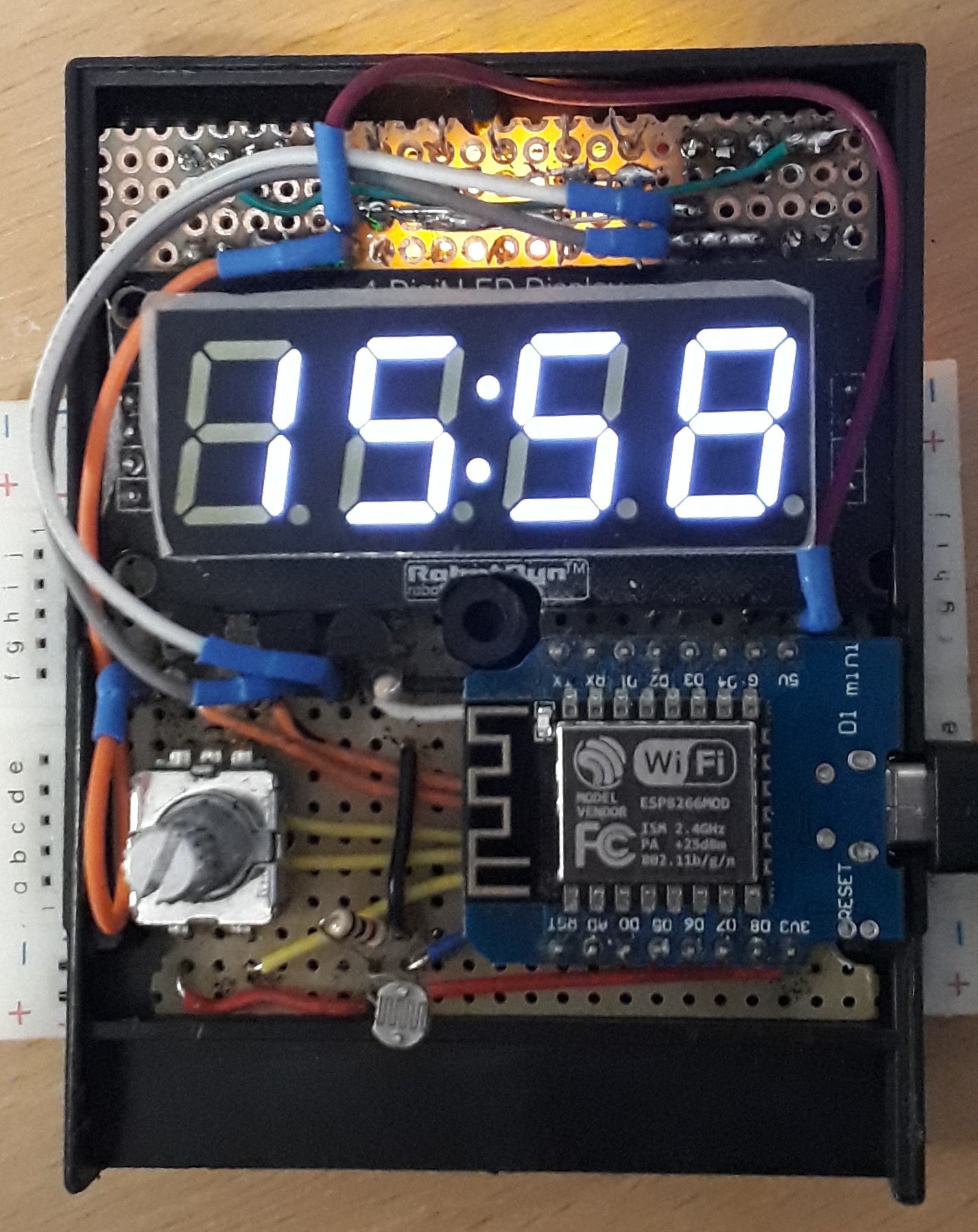
Front cover open
The Wemos D1 has the CH340 on bottom side. it doesn't collide with the wires because the D1 is raised a little. The jumper wires are 10cm 'dupont' jumper wires with the black plastic replaced with heat shrink tube and then bent at the flat part of the connector. On this photo I have a white display. Later I replaced it with a red version.
Front cover open
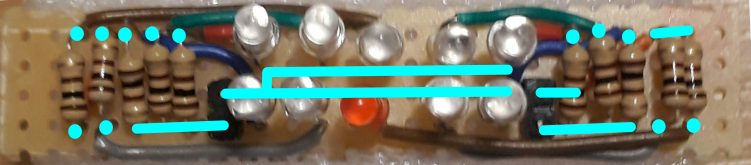
LED board soldering
The central LEDs are 3 yellow and one red. left and right block use 3 yellow LEDs each. The LEDs are soldered only on the power 'rail', the other leg is only tight in the hole with the wire. this allows to aim the LEDs
LED board soldering
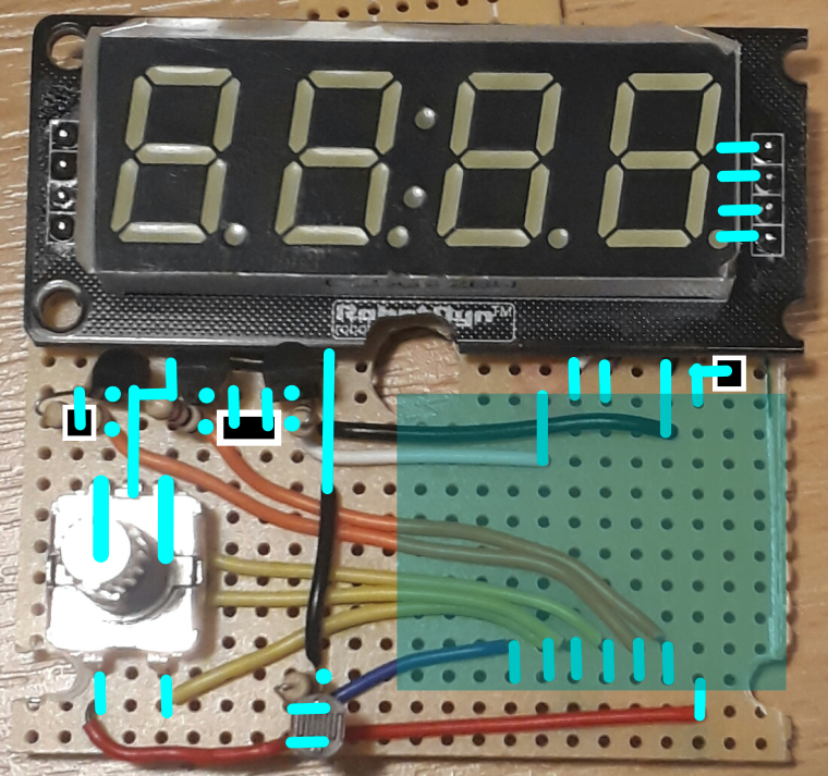
main board soldering
If I would make the board again, I would put the encoder and the LDR higher and position the transistors at bottom.
main board soldering
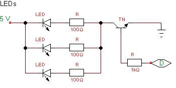
One LED group circuit
One LED group circuit
LED board soldering
The central LEDs are 3 yellow and one red. left and right block use 3 yellow LEDs each. The LEDs are soldered only on the power 'rail', the other leg is only tight in the hole with the wire. this allows to aim the LEDs
LED board soldering
Front cover open
The Wemos D1 has the CH340 on bottom side. it doesn't collide with the wires because the D1 is raised a little. The jumper wires are 10cm 'dupont' jumper wires with the black plastic replaced with heat shrink tube and then bent at the flat part of the connector. On this photo I have a white display. Later I replaced it with a red version.
Front cover open
main board soldering
If I would make the board again, I would put the encoder and the LDR higher and position the transistors at bottom.
main board soldering
One LED group circuit
One LED group circuit
Comments
Only logged in users can leave comments