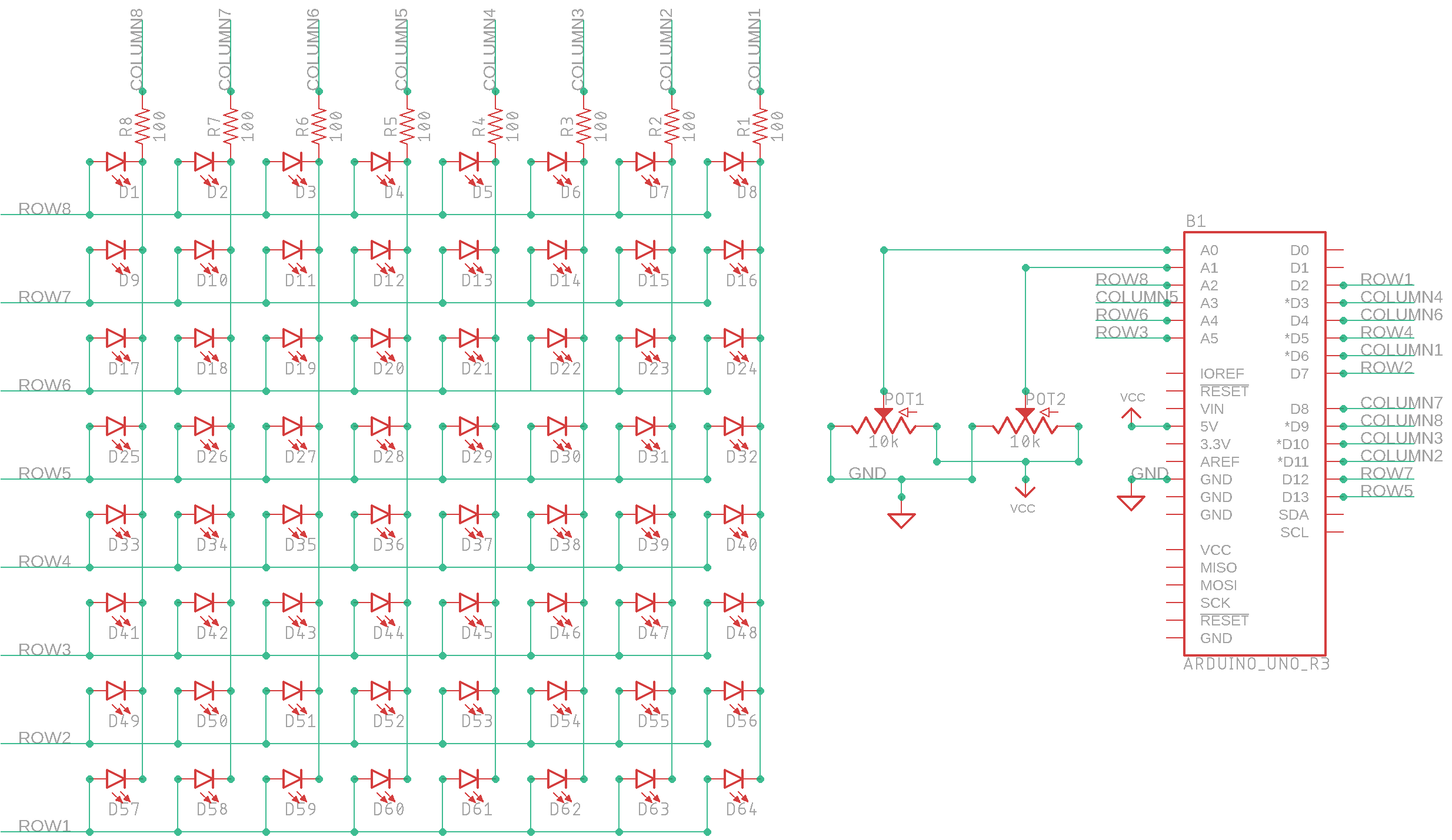
Row-Column Scanning & DIY 8x8 LED Matrix
Stolen from Arduino.cc, ArduiNoob-friendly.
Devices & Components
1
Arduino Uno Rev3
2
Rotary potentiometer (generic)
8
Resistor 100 ohm
1
Jumper wires (generic)
64
LED (generic)
1
Solderless Breadboard Full Size
Hardware & Tools
1
Soldering iron (generic)
1
Blank PCB
Software & Tools
Arduino IDE
Project description
Code
RowColScan.ino
arduino
1/*
2  Row-Column Scanning an 8x8 LED matrix with X-Y input
3
4  This  example controls an 8x8 LED matrix using two analog inputs.
5
6  This example  works for the Lumex LDM-24488NI Matrix. See
7  http://sigma.octopart.com/140413/datasheet/Lumex-LDM-24488NI.pdf
8  for the pin connections.
9
10  For other LED cathode column matrixes, you should  only need to change the pin
11  numbers in the row[] and column[] arrays.
12
13  rows are the anodes
14  cols are the cathodes
15  ---------
16
17  Pin numbers:
18  Matrix:
19  - digital pins 2 through 13,
20  - analog pins 2 through 5 used  as digital 16 through 19
21  Potentiometers:
22  - center pins are attached to  analog pins 0 and 1, respectively
23  - side pins attached to +5V and ground, respectively
24
25  created 27 May 2009
26  modified 30 Aug 2011
27  by Tom Igoe
28
29  This example  code is in the public domain.
30
31  http://www.arduino.cc/en/Tutorial/RowColumnScanning
32
33  see also http://www.tigoe.net/pcomp/code/category/arduinowiring for more
34*/
35
36//  2-dimensional array of row pin numbers:
37const int row[8] = {
38  2, 7, 19, 5,  13, 18, 12, 16
39};
40
41// 2-dimensional array of column pin numbers:
42const  int col[8] = {
43  6, 11, 10, 3, 17, 4, 8, 9
44};
45
46// 2-dimensional array  of pixels:
47int pixels[8][8];
48
49// cursor position:
50int x = 5;
51int  y = 5;
52
53void setup() {
54  // initialize the I/O pins as outputs iterate  over the pins:
55  for (int thisPin = 0; thisPin < 8; thisPin++) {
56    // initialize  the output pins:
57    pinMode(col[thisPin], OUTPUT);
58    pinMode(row[thisPin],  OUTPUT);
59    // take the col pins (i.e. the cathodes) high to ensure that the  LEDS are off:
60    digitalWrite(col[thisPin], HIGH);
61  }
62
63  // initialize  the pixel matrix:
64  for (int x = 0; x < 8; x++) {
65    for (int y = 0; y <  8; y++) {
66      pixels[x][y] = HIGH;
67    }
68  }
69}
70
71void loop()  {
72  // read input:
73  readSensors();
74
75  // draw the screen:
76  refreshScreen();
77}
78
79void  readSensors() {
80  // turn off the last position:
81  pixels[x][y] = HIGH;
82  // read the sensors for X and Y values:
83  x = 7 - map(analogRead(A0), 0, 1023,  0, 7);
84  y = map(analogRead(A1), 0, 1023, 0, 7);
85  // set the new pixel position  low so that the LED will turn on in the next
86  // screen refresh:
87  pixels[x][y]  = LOW;
88
89}
90
91void refreshScreen() {
92  // iterate over the rows (anodes):
93  for (int thisRow = 0; thisRow < 8; thisRow++) {
94    // take the row pin (anode)  high:
95    digitalWrite(row[thisRow], HIGH);
96    // iterate over the cols (cathodes):
97    for (int thisCol = 0; thisCol < 8; thisCol++) {
98      // get the state of  the current pixel;
99      int thisPixel = pixels[thisRow][thisCol];
100      //  when the row is HIGH and the col is LOW,
101      // the LED where they meet turns  on:
102      digitalWrite(col[thisCol], thisPixel);
103      // turn the pixel off:
104      if (thisPixel == LOW) {
105        digitalWrite(col[thisCol], HIGH);
106      }
107    }
108    // take the row pin low to turn off the whole row:
109    digitalWrite(row[thisRow],  LOW);
110  }
111}
112
RowColScan.ino
arduino
1/*
2  Row-Column Scanning an 8x8 LED matrix with X-Y input
3
4  This
5  example controls an 8x8 LED matrix using two analog inputs.
6
7  This example
8  works for the Lumex LDM-24488NI Matrix. See
9  http://sigma.octopart.com/140413/datasheet/Lumex-LDM-24488NI.pdf
10
11  for the pin connections.
12
13  For other LED cathode column matrixes, you should
14  only need to change the pin
15  numbers in the row[] and column[] arrays.
16
17
18  rows are the anodes
19  cols are the cathodes
20  ---------
21
22  Pin numbers:
23
24  Matrix:
25  - digital pins 2 through 13,
26  - analog pins 2 through 5 used
27  as digital 16 through 19
28  Potentiometers:
29  - center pins are attached to
30  analog pins 0 and 1, respectively
31  - side pins attached to +5V and ground, respectively
32
33
34  created 27 May 2009
35  modified 30 Aug 2011
36  by Tom Igoe
37
38  This example
39  code is in the public domain.
40
41  http://www.arduino.cc/en/Tutorial/RowColumnScanning
42
43
44  see also http://www.tigoe.net/pcomp/code/category/arduinowiring for more
45*/
46
47//
48  2-dimensional array of row pin numbers:
49const int row[8] = {
50  2, 7, 19, 5,
51  13, 18, 12, 16
52};
53
54// 2-dimensional array of column pin numbers:
55const
56  int col[8] = {
57  6, 11, 10, 3, 17, 4, 8, 9
58};
59
60// 2-dimensional array
61  of pixels:
62int pixels[8][8];
63
64// cursor position:
65int x = 5;
66int
67  y = 5;
68
69void setup() {
70  // initialize the I/O pins as outputs iterate
71  over the pins:
72  for (int thisPin = 0; thisPin < 8; thisPin++) {
73    // initialize
74  the output pins:
75    pinMode(col[thisPin], OUTPUT);
76    pinMode(row[thisPin],
77  OUTPUT);
78    // take the col pins (i.e. the cathodes) high to ensure that the
79  LEDS are off:
80    digitalWrite(col[thisPin], HIGH);
81  }
82
83  // initialize
84  the pixel matrix:
85  for (int x = 0; x < 8; x++) {
86    for (int y = 0; y <
87  8; y++) {
88      pixels[x][y] = HIGH;
89    }
90  }
91}
92
93void loop()
94  {
95  // read input:
96  readSensors();
97
98  // draw the screen:
99  refreshScreen();
100}
101
102void
103  readSensors() {
104  // turn off the last position:
105  pixels[x][y] = HIGH;
106
107  // read the sensors for X and Y values:
108  x = 7 - map(analogRead(A0), 0, 1023,
109  0, 7);
110  y = map(analogRead(A1), 0, 1023, 0, 7);
111  // set the new pixel position
112  low so that the LED will turn on in the next
113  // screen refresh:
114  pixels[x][y]
115  = LOW;
116
117}
118
119void refreshScreen() {
120  // iterate over the rows (anodes):
121
122  for (int thisRow = 0; thisRow < 8; thisRow++) {
123    // take the row pin (anode)
124  high:
125    digitalWrite(row[thisRow], HIGH);
126    // iterate over the cols (cathodes):
127
128    for (int thisCol = 0; thisCol < 8; thisCol++) {
129      // get the state of
130  the current pixel;
131      int thisPixel = pixels[thisRow][thisCol];
132      //
133  when the row is HIGH and the col is LOW,
134      // the LED where they meet turns
135  on:
136      digitalWrite(col[thisCol], thisPixel);
137      // turn the pixel off:
138
139      if (thisPixel == LOW) {
140        digitalWrite(col[thisCol], HIGH);
141      }
142
143    }
144    // take the row pin low to turn off the whole row:
145    digitalWrite(row[thisRow],
146  LOW);
147  }
148}
149
Downloadable files
My Simple Schematic
My Simple Schematic
Comments
Only logged in users can leave comments