Devices & Components
Arduino Nano
Battery Holder, AA x 2
SparkFun RedBot Sensor - Line Follower
Slide Switch
Wheels for the motors
9V Battery Clip
AA Batteries
DC Motor, 12 V
9V battery (generic)
L298n Motor Driver
Hardware & Tools
3d pen (optional)
Software & Tools
Arduino IDE
Project description
Code
Main code
c_cpp
This is the entire code, if you want to make this project by yourself.
Main code
c_cpp
This is the entire code, if you want to make this project by yourself.
Downloadable files
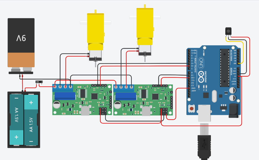
Circuit layout
This is the entire circuit. If you have the specified driver you wont have to do all the mess with two drivers. You might have to make some changes if you use 1.5v batteries instead of 1.2v, couse the driver only supports up to 12v before you have to power it with aditional 5v for the inner circuitry, but you can probably figure that out.
Circuit layout
Comments
Only logged in users can leave comments