Remote Weather Station
A remote weather station that uses two arduinos, one as a transmitter and one as a data-logging receiver.
Devices & Components
Arduino Uno Rev3
SparkFun XBee Explorer USB
Coin cell battery
DfRobot XBee Shield
SD card
9 volt power supply
Stack Through Headers
Half Breadboard
8' White Exterior Extension Cord
USB A to mini USB B
OLED
ABS electrical box
M/F Jumper Wire
Alphanumeric LCD, 16 x 2
BME 280 Sensor
ABS Plastic Waterproof Electronic Box
SD card reader/writer
Jumper Wire
Adafruit Logging Sheild
Xbee RF TXRX MODULE 802.15.4 Wire Ant
Potentiometer
Hardware & Tools
Saw
Soldering iron (generic)
Drill
Hole Saw
Software & Tools
XCTU
Arduino IDE
Project description
Code
TempPresHumLCD_Station_Reciever_No_Logger.ino
arduino
If you do not want to log the data coming into the receiver use this sketch.
TempPresHumLCD_Station_Reciever_Final.ino
arduino
This is the sketch for the data logging remote weather station receiver.
XBee Radio Testing from Jeremy Blum's arduino_read_pot.ino from, "Exploring Arduino.com/content/ch6"
arduino
Use this sketch to test XBee Radios
TempPresHumOLED_Station_Transmitter_Final.ino
arduino
This is an update to the original sketch for the remote weather station transmitter. After completing a comparison of multiple temperature and humidity records with other local sensor records, the calibration for temperature and humidity have been adjusted.
TempPresHumLCD_Station_Reciever_No_Logger.ino
arduino
If you do not want to log the data coming into the receiver use this sketch.
TempPresHumOLED_Station_Transmitter_Final.ino
arduino
This is an update to the original sketch for the remote weather station transmitter. After completing a comparison of multiple temperature and humidity records with other local sensor records, the calibration for temperature and humidity have been adjusted.
TempPresHumLCD_Station_Reciever_Final.ino
arduino
This is the sketch for the data logging remote weather station receiver.
XBee Radio Testing from Jeremy Blum's arduino_read_pot.ino from, "Exploring Arduino.com/content/ch6"
arduino
Use this sketch to test XBee Radios
Downloadable files
Transmitter Installation 4
Mounting the birdhouse cabinet over electric housing.
Transmitter Installation 4
Transmitter Installation 3
detail
Transmitter Installation 3
Adafruit BME280 Tutorial
Helpful tutorial for the BME sensor
Adafruit BME280 Tutorial
Receiver Circuit Diagram
This is the circuit diagram for the receiver. Be sure to consult the photos for how to wire the power to the XBee Shield and breadboard.
Receiver Circuit Diagram

Receiver
This image illustrates how to wire the Receiver.
Receiver
Transmitter Installation 1
Mounting the transmitter
Transmitter Installation 1
Transmitter Installation 8
Weather station on shed.
Transmitter Installation 8
Transmitter Installation 2
detail
Transmitter Installation 2
Power supply for Xbee shield
NOTE: Now the Stacking Header Pin kits have headers for the ICSP pins. So if you have the new kits you can skip this example for supplying power to the peripherals. If you skip these steps you will have to solder male header pins on the Xbee Shield to supply power for the 3 & 5 Volt components. The data logger on the receiver blocks the power supply for the Xbee. These three images show how to wire around that and transmit power to the ICSP socket on the Xbee shield.
Power supply for Xbee shield
Transmitter Installation 7
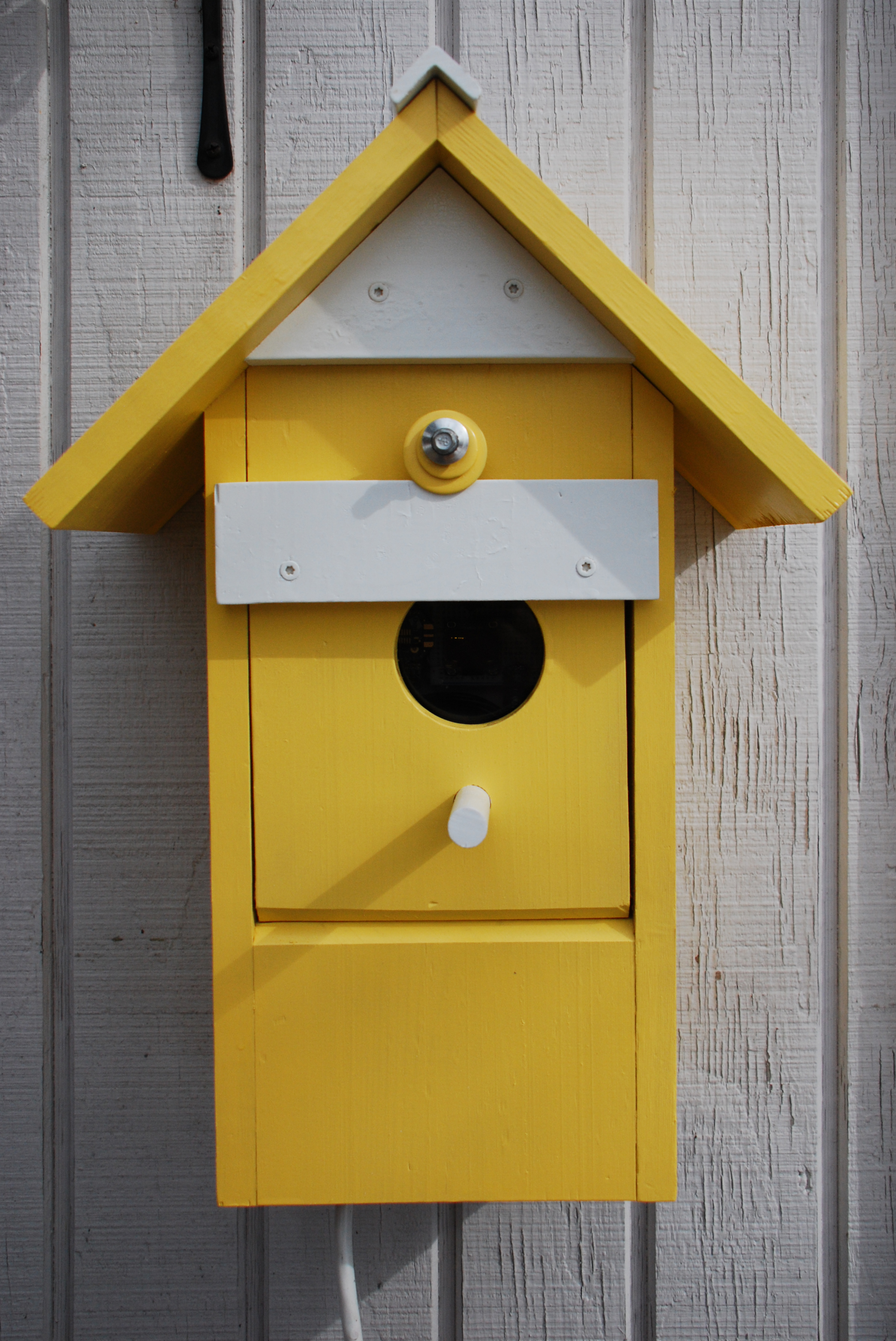
Viewing window for OLED. The camera used fast shutter speed so the OLED data looks broken, the OLED actually works fine.
Transmitter Installation 7
Transmitter Installation 5
Completed birdhouse
Transmitter Installation 5
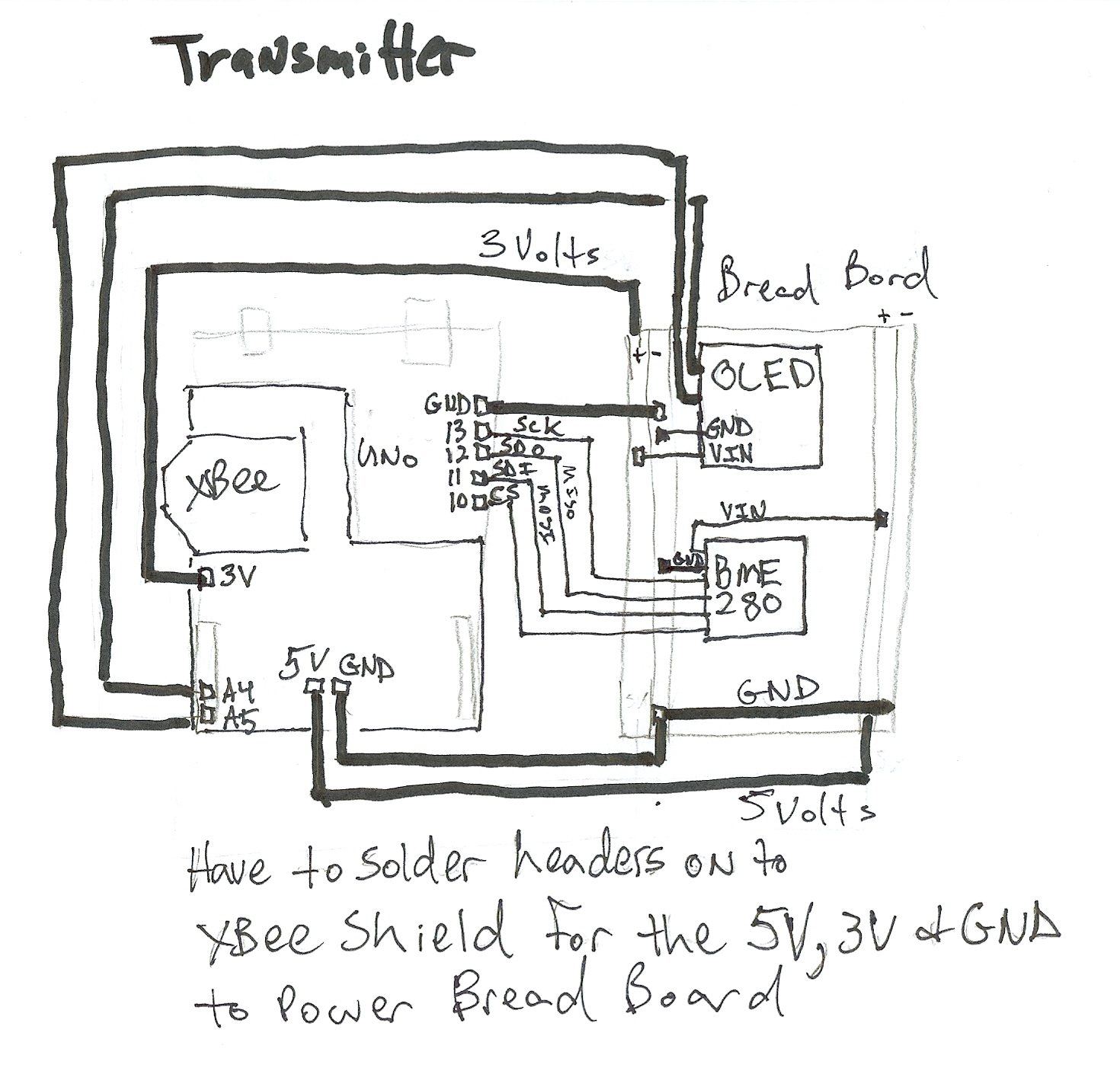
Transmitter Circuit Diagram
This is the circuit diagram for the transmitter.
Transmitter Circuit Diagram
Sample of recorded data and graph
This is an example of data from the SD card of the Data Logger. I am using a Windows computer, so the data is opened in Excel and graphed within that application.
Sample of recorded data and graph
receiver_box_build_(2)_lk64rZMpLZ.JPG
receiver_box_build_(2)_lk64rZMpLZ.JPG
Transmitter Installation 6
Open front for access to electrical box for reprogramming.
Transmitter Installation 6
Transmitter Wiring Example
This image illustrates how to wire the transmitter. Additionally, male header pins must be soldered to the Xbee shield in order to supply both the 5 volt and 3 volts necessary for the OLED and BME280 sensor.
Transmitter Wiring Example
Adafruit Logging Shield Tutorial
This tutorial walks through the set up of the logging shield and setting the real time clock.
Adafruit Logging Shield Tutorial
receiver_box_build_(1)_nf92bPIM1D.JPG
receiver_box_build_(1)_nf92bPIM1D.JPG
Sample of recorded data and graph
This is an example of data from the SD card of the Data Logger. I am using a Windows computer, so the data is opened in Excel and graphed within that application.
Sample of recorded data and graph
receiver_box_build_(2)_lk64rZMpLZ.JPG
receiver_box_build_(2)_lk64rZMpLZ.JPG
Transmitter Circuit Diagram
This is the circuit diagram for the transmitter.
Transmitter Circuit Diagram
Transmitter Installation 2
detail
Transmitter Installation 2
Transmitter Installation 8
Weather station on shed.
Transmitter Installation 8
Transmitter Installation 7
Viewing window for OLED. The camera used fast shutter speed so the OLED data looks broken, the OLED actually works fine.
Transmitter Installation 7
Adafruit BME280 Tutorial
Helpful tutorial for the BME sensor
Adafruit BME280 Tutorial
Receiver
This image illustrates how to wire the Receiver.
Receiver
Receiver Circuit Diagram
This is the circuit diagram for the receiver. Be sure to consult the photos for how to wire the power to the XBee Shield and breadboard.
Receiver Circuit Diagram
Transmitter Installation 4
Mounting the birdhouse cabinet over electric housing.
Transmitter Installation 4
Power supply for Xbee shield
NOTE: Now the Stacking Header Pin kits have headers for the ICSP pins. So if you have the new kits you can skip this example for supplying power to the peripherals. If you skip these steps you will have to solder male header pins on the Xbee Shield to supply power for the 3 & 5 Volt components. The data logger on the receiver blocks the power supply for the Xbee. These three images show how to wire around that and transmit power to the ICSP socket on the Xbee shield.
Power supply for Xbee shield
Transmitter Installation 3
detail
Transmitter Installation 3
Transmitter Installation 6
Open front for access to electrical box for reprogramming.
Transmitter Installation 6
Notes for configuring Xbee radios
The configuration approach highlighted by Blum requires changes to be made with the XTCU application. The attached PDF file walks through the steps to do this .
Notes for configuring Xbee radios
Transmitter Wiring Example
This image illustrates how to wire the transmitter. Additionally, male header pins must be soldered to the Xbee shield in order to supply both the 5 volt and 3 volts necessary for the OLED and BME280 sensor.
Transmitter Wiring Example
Adafruit Logging Shield Tutorial
This tutorial walks through the set up of the logging shield and setting the real time clock.
Adafruit Logging Shield Tutorial
receiver_box_build_(1)_nf92bPIM1D.JPG
receiver_box_build_(1)_nf92bPIM1D.JPG
Transmitter Installation 5
Completed birdhouse
Transmitter Installation 5
Transmitter Installation 1
Mounting the transmitter
Transmitter Installation 1
Comments
Only logged in users can leave comments