Magic Eyes
I built a project using 8x8 LED matrix without using MAX7219 or any extra library files because they make code difficult to understand.
Devices & Components
1
Arduino Uno Rev3
34
Jumper wires (generic)
1
Infrared Sensor
1
Led Matrix
1
Breadboard (generic)
Software & Tools
Arduino IDE
Project description
Code
Led Matrix
arduino
Downloadable files
Circuitous
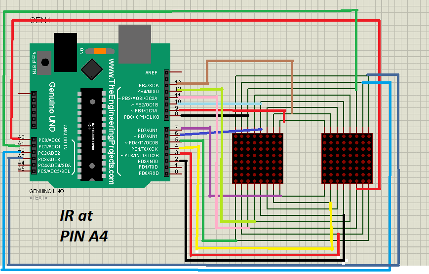
Simply do the connection as done in the image and put Infrared sensor at PIN A4. Provide Vin and GND to both Infrared sensor and Arduino.
Circuitous
Circuitous
Simply do the connection as done in the image and put Infrared sensor at PIN A4. Provide Vin and GND to both Infrared sensor and Arduino.
Circuitous
Comments
Only logged in users can leave comments